C:\MyFiles\Pagemaker\MECH INSP list02.pmd - Pikes Peak ...
C:\MyFiles\Pagemaker\MECH INSP list02.pmd - Pikes Peak ...
C:\MyFiles\Pagemaker\MECH INSP list02.pmd - Pikes Peak ...
You also want an ePaper? Increase the reach of your titles
YUMPU automatically turns print PDFs into web optimized ePapers that Google loves.
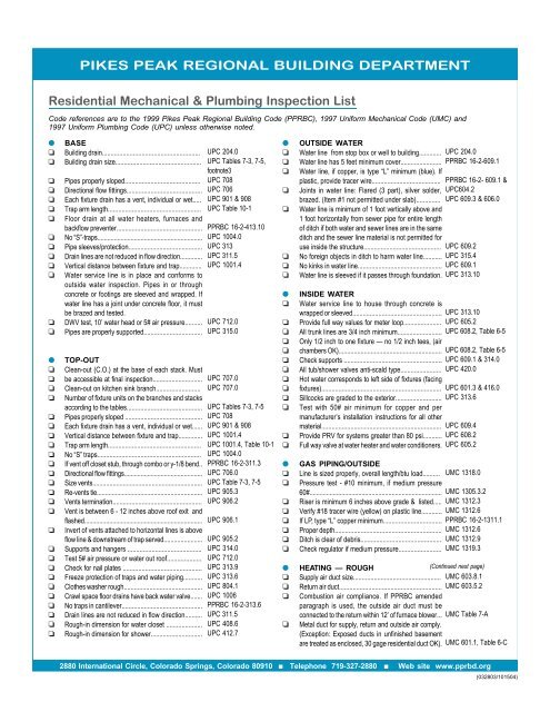
RESIDENTIAL MECHANICAL AND PLUMBING <strong>INSP</strong>ECTIONS●❏❏❏❏❏❏❏❏❏❏❏❏❏❏❏❏❏❏❏●❏❏❏HEATING — ROUGH (Continued from previous page)Factory-made air ducts are listed and installed per theirlistings and UL181. .....................................................Only Class 0 or Class 1 air ducts may be installed;flexible air connector is not permitted.............................Joints of ducts are substantially air tight by means oftape, mastics, gaskets or other means for round ducts...Residential round duct crimp joints have 1 1/2 inch lapat each joint and are fastened with 3 screws equallyspaced around the joint.................................................Rectangular duct joints and seams constructedcorrectly, (S-slip and drive or 1 inch pocket lock isstandard).......................................................................Minimum 1 inch of core over collar, pipe or fitting, andsecured with minimum 2 wraps of approved duct tapeor clamp (zip tie)................................................................Jacket and insulation pulled back over core andwrapped at least twice with approved duct tape..............Ducts are securely fastened at each directional change..Supports for rectangular ducts..........................................Supports for round ducts...................................................Flex duct...........................................................................Metal ducts are installed with minimum 4 inchesseparation from earth. Metal ducts installed in or underconcrete slab are encased in minimum 2 inches ofconcrete......................................................................Factory-made air ducts are installed with minimum 4inches separation from earth and protected fromphysical damage..............................................................Insulation of ducts. Supply and return-air ducts andplenums of heating or cooling systems are insulatedwith not less than UMC requirements or the PPRBC.Note: The 2000 International Energy ConservationCode (IECC) as amended by PPRBC became effectivein October 2003 in Colorado Springs, and February2004 in El Paso County. Where conflicts between thetwo codes exist, the most stringent criteria applies...........Environmental air ducts. Exhaust ducts terminateoutside the building and are equipped with back draftdampers. Bath exhaust may terminate within 12 inchesand directed at the attic vent........................................Domestic clothes dryer ducts are made of metal with asmooth interior surface..................................................Domestic clothes dryers are not fastened with screwsor other fasteners that will obstruct flow........................Clothes dryer duct length...................................................Exhaust outlets terminate not less than 3’ from propertyline or openings into normally occupied areas of buildings.UMC 601.5UMC 603.2UMC 601.6UMC 601.6.1UMC 601.6.2, Table 6-AUMC Standard 6-3,6.308.1.2UMC Standard 6-3,6.308.1.3UMC 603.1, Table 6-EUMC 603.1.2, Table 6-EUMC 603.1.3, Table 6-EUMC Standard 6-3, 6.309.1UMC 603.1UMC 603.2.2UMC 604.1, Table 6-DPPRBC 16-2-604.1IECCUMC 504.1UMC 504.3UMC 504.3.1PPRBC 16-2-504.3.2UMC 504.6VENTVent must be listed............................................................. UMC 801 & 803.1Vent is suitable for type of fuel (B or L)............................... UMC 801Vent is properly sized. (KNOW THE GAMMA TABLES:All venting systems in PPRBD jurisdiction are sized perthe July 1991 revised edition of the Gamma Tables ormanufacturer’s specs. Any offset that takes the pipeout of line and back again, regardless of fitting, is anoffset and constitutes a 20% reduction in the maximumbtu capacity of the common vent. If the vent offsets lessthan the diameter of the pipe, (you can see through it),no reductions are taken. A manifold system includingthe horizontal tee or wye and one 90 o elbow to thevertical causes a 10% reduction in the btu capacity ofthe common vent. See footnotes: 1 - 6, 9, 19, 21, 22,20 and 31 in the Gamma Table booklet.(Continued this page)●❏❏❏❏❏❏●❏❏❏❏❏❏❏❏❏●❏❏❏❏❏❏❏❏❏❏❏❏●❏❏❏❏❏❏❏❏❏❏❏❏❏❏VENTVent clearance..................................................................Vent connector has adequate pitch...................................Vent offsets.......................................................................Joints mechanically secured................................................Vent connector clearance to combustible.............................Horizontal portion of connector is run correctly.GAS PIPING/INSIDELine is sized properly, overall length/btu load. If CSSTsystem, contractor’s chart is on job site.............................Check if pressure test is holding. 10# minimum, if mediumpressure 60#.......................................................................Verify gap between line and riser at minimum 18 inches.Proper supports.....................................................................Utility requirement. Gap between line and riser is at least18 inches..............................................................................If LP gas is going to be used, approved means of removalmust be provided — LP drain or detector............................No unions except downstream of gas shut off at appliances.Right/Left nipples with couplings........................................No concealed bushings.......................................................PLUMBING FINALClearance at all cleanouts and tightness of plugs tested.....T&P valve and termination at water heater.........................Adequate water to each fixture...........................................Fixture is sealed at wall and floor........................................Backflow prevention devices at toilets, hose outlets, lawnsprinkling system.................................................................Location of floor drain and strainer is installed. Clean outplug on “Kansas City” pattern...............................................Vent terminals and flashing..................................................Dishwasher drain connects to sanitary via air gap.............All plumbing fixtures set or drain lines capped...................Hot water corresponds to left side fixture (facing)...............Sillcocks checked for drainage and backflow preventiondevice.....................................................................................Meter installed if applicable (utility requirement).HEATING FINALCheck vent cap/storm collar/vent termination...................Exhaust terminals for dryers, bathroom, etc. Back draftdampers or screens.............................................................Gas pipe bonded with electrical.........................................All gas outlets are connected to all appliances or plugged....Listed fuel gas connector to be outside appliance housing....Filters are in place................................................................Thermostat (or thermostats) installed...................................Adequate combustion air.......................................................Electrical outlets/connections installed...............................Water heater/furnace in garage or only access from garagemust be minimum of 18 inches above floor.......................Mechanical room opening is minimum 2’ width; workingspace not less than 30” depth & height in front of appliance...Appliances supported from ground, concrete slab not lessthan 3 inches above natural grade....................................Furnace-attic or furred space minimum opening 30” x 22”& minimum pathway of 30” vertical and 24” wide. Unit notmore than 20’ from the opening. Contractor providesinspection access.................................................................Furnace under floor space access minimum opening 30” x30”, must be 20’ or less from opening. Cannot accessthrough garage...................................................................UMC 803.1UMC 805UMC 801, 812.1UMC 805.3UMC 805.2UMC 1318.0UMC 1305.3.2UMC Table 13-APPRBC 16-2- 304.5 &PPRBC 16-2-1314.1UMC 1312.11UMC 1312.11UPC 707.10UPC 608.5UPC 601.1UPC 408.2UPC 602, 603PPRBC 16-2-413.10 &UPC 405.1UPC 906UPC 807.4PPRBC 16-2-413 &UPC 419UPC 416, 601.3UPC 313.6UMC 803.1, 806UMC 504.1, 504.6PPRBC 16-2-1312.18UMC 1307.2UMC 1313UMC 402.3UMC 311UMC Table 7-AUMC 306UMC 303.1.3UMC 307.2 &PPRBC 16-2-304.7UMC 304.8UMC 307.3UMC 307.42880 International Circle, Colorado Springs, Colorado 80910 ■ Telephone 719-327-2880 ■ Web site www.pprbd.org


