Nr 1 - ITME
Nr 1 - ITME
Nr 1 - ITME

Create successful ePaper yourself
Turn your PDF publications into a flip-book with our unique Google optimized e-Paper software.
I. Kujawa, A. Filipowski, D. Pysz, ...<br />
(a) (b) (c)<br />
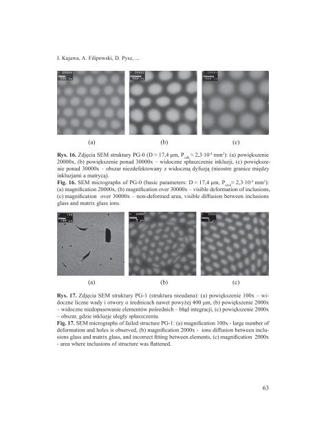
Rys. 16. Zdjęcia SEM struktury PG-0 (D ≈ 17,4 μm, P całk.<br />
≈ 2,3·10 -4 mm 2 ): (a) powiększenie<br />
20000x, (b) powiększenie ponad 30000x – widoczne spłaszczenie inkluzji, (c) powiększenie<br />
ponad 30000x – obszar niezdefektowany z widoczną dyfuzją (nieostre granice między<br />
inkluzjami a matrycą).<br />
Fig. 16. SEM micrographs of PG-0 (basic parameters: D ≈ 17,4 μm, P total<br />
≈ 2,3·10 -4 mm 2 ):<br />
(a) magnification 20000x, (b) magnification over 30000x – visible deformation of inclusions,<br />
(c) magnification over 30000x – non-deformed area, visible diffusion between inclusions<br />
glass and matrix glass ions.<br />
(a) (b) (c)<br />
Rys. 17. Zdjęcia SEM struktury PG-1 (struktura nieudana): (a) powiększenie 100x – widoczne<br />
liczne wady i otwory o średnicach nawet powyżej 400 μm, (b) powiększenie 2000x<br />
– widoczne niedopasowanie elementów pośrednich – błąd integracji, (c) powiększenie 2000x<br />
– obszar, gdzie inkluzje uległy spłaszczeniu.<br />
Fig. 17. SEM micrographs of failed structure PG-1: (a) magnification 100x - large number of<br />
deformation and holes is observed, (b) magnification 2000x - ions diffusion between inclusions<br />
glass and matrix glass, and incorrect fitting between elements, (c) magnification 2000x<br />
- area where inclusions of structure was flattened.<br />
63