Ranger Install Manual - Code 3 Public Safety Equipment
Ranger Install Manual - Code 3 Public Safety Equipment
Ranger Install Manual - Code 3 Public Safety Equipment

You also want an ePaper? Increase the reach of your titles
YUMPU automatically turns print PDFs into web optimized ePapers that Google loves.
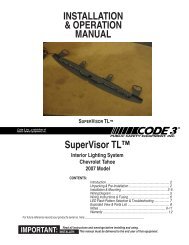
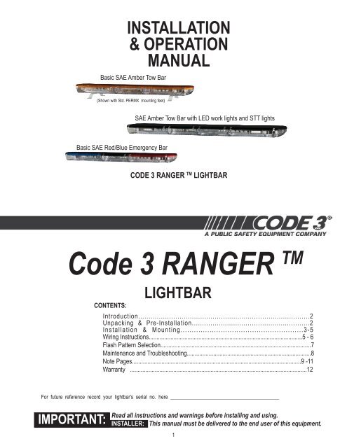
INSTALLATION& OPERATIONMANUALBasic SAE Amber Tow Bar(Shown with Std. PERMX mounting feet)SAE Amber Tow Bar with LED work lights and STT lightsBasic SAE Red/Blue Emergency BarcODE 3 rANGER TM LIGHTBAR<strong>Code</strong> 3 RANGER TMCONTENTS:LIGHTBARIntroduction...................................................................................2Unpacking & Pre-<strong>Install</strong>ation.........................................................2<strong>Install</strong>ation & Mounting.......................................................3-5Wiring Instructions...................................................................................................5 - 6Flash Pattern Selection.................................................................................................7Maintenance and Troubleshooting................................................................................8Note Pages.............................................................................................................9 -11Warranty ..................................................................................................................12For future reference record your lightbar's serial no. here __________________________________________IMPORTANT:Read all instructions and warnings before installing and using.INSTALLER: This manual must be delivered to the end user of this equipment.1
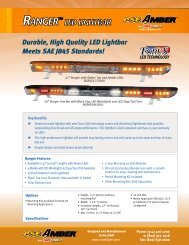
IntroductionThe <strong>Ranger</strong> TM Light Bar is designed utilizing the newly designed Torus Technology TM optics. The low profile and aerodynamic linesreduce air drag, which results in fuel savings and stability at high speeds. This light bar has a strong extruded internal frame, shockresistantpolycarbonate lenses, and warning signals that exceed SAE standards. The light bar is designed on a modular basis, whichmeans that the light bar can be customized with available options designed for this light bar such as STT lights and additional directionalLED modules.!warning!The use of this or any warning device does not ensure that all drivers can or will observe or react to anemergency warning signal. Never take the right-of-way for granted. It is your responsibility to be sure you canproceed safely before entering an intersection, driving against traffic, responding at a high rate of speed, orwalking on or around traffic lanes.The effectiveness of this warning device is highly dependent upon correct mounting and wiring. Read andfollow the manufacturer’s instructions before installing or using this device. The vehicle operator should insuredaily that all features of the device operate correctly. In use, the vehicle operator should insure the projectionof the warning signal is not blocked by vehicle components (i.e.: open trunks or compartment doors), people,vehicles, or other obstructions.This equipment is intended for use by authorized personnel only. It is the user’s responsibility to understandand obey all laws regarding emergency warning devices. The user should check all applicable city, state andfederal laws and regulations.<strong>Code</strong> 3, Inc., assumes no liability for any loss resulting from the use of this warning device.Proper installation is vital to the performance of this warning device and the safe operation of the emergencyvehicle. It is important to recognize that the operator of the emergency vehicle is under psychological andphysiological stress caused by the emergency situation. The warning device should be installed in such amanner as to: A) Not reduce the output performance of the system, B) Place the controls within convenientreach of the operator so that he can operate the system without losing eye contact with the roadway.Emergency warning devices often require high electrical voltages and/or currents. Properly protect and usecaution around live electrical connections. Grounding or shorting of electrical connections can cause high currentarcing, which can cause personal injury and/or severe vehicle damage, including fire.PROPER INSTALLATION COMBINED WITH OPERATOR TRAINING IN THE PROPER USE OF EMERGEN-CY WARNING DEVICES IS ESSENTIAL TO INSURE THE SAFETY OF EMERGENCY PERSONNEL ANDTHE PUBLIC.Wiring Instructions (read CarefullyBefore <strong>Install</strong>ation)Unpacking & Pre-installationCarefully remove the light bar and place it on a flat surface, taking care not to scratch the lenses or damage the cable coming out of thebottom. Examine the unit for transit damage, broken lamps, etc. Report any damage to the carrier and keep the shipping carton.Standard light bars are built to operate on 12 volt D.C. negative ground (earth) vehicles. If you have an electrical system other than 12volt D.C. negative ground (earth), and have not ordered a specially wired light bar, contact the factory for instructions.Test the unit before installation. To test, touch the Red & Red/White wire to the ground (earth) and the other wires to +12 volts D.C., inaccordance with the instructions attached to the cable (an automotive battery is preferable for this test). A battery charger may be used,If problems occur at this point, contact the factory.2
<strong>Install</strong>ation & Mountingwarning!!Utilizing non-factory supplied screws and/or mounting brackets and/or the impropernumber of screws may result in loss of warranty coverage on the equipment.PERMX Std. mounting kit: (Provided with the light bar) For flat roof installations.1. Mount the PERMX mounting feet to the bottom of the light bar frame using the stainless steel hardwaresupplied in the kit. Carriage bolts are slid into the frame ends to the desired location on the frame rails.2. Position the bar onto the vehicle roof and center in desired location.3. Mark the roof using the holes in the mounting feet as a template for screw hole locations.4. Remove the light bar from the roof of the vehicle and center punch the (4) mounting holes using a centerpunch. (This will prevent drill (walking) during drilling operations)5. Drill roof of vehicle to accept mounting screws being installed.6. Set bar onto roof and check for levelness of bar front to back using a level.7. Place shims under feet of mounting foot if needed to acheive level attitude.8. <strong>Install</strong> (4) foam pads under mounting feet to prevent etching of painted surfaces.9. It is recommended that a bead of silicone sealant be used around each mounting hole in roof to assureagainst any water infiltration.10. <strong>Install</strong> mounting bolts through vehicle roof up into mounting feet of light bar.OTHER MOUNTING OPTIONS:Mounting HardwareAll mounting hardware is packed in a small box inside the main carton. The standard kit included with the bar is the PERMX mount. Othermounting options can be bought separately such as: : (1) Hook-On Type, (1) Tow and Recovery and a second Permanent Type. Theseare discussed in detail later. Note: Hook-on mounting for "gutterless" type vehicles will require a special hook for mounting. Severalspecial application hooks are available. Contact the factory for details.Hook-on MountingBegin the installation by attaching the rubber feet to the mounting brackets using the black 1/4" carriage bolts and 1/4" nuts provided.See Figure 1. (Do not install shims at this time). Place the light bar upside down on a table or other work surface, being careful not toscratch the lenses. Slide the 5/16" carriage bolts into the frame. Secure the mounting brackets finger tight so they support the weightof the light bar, but can still be positioned. Locate the vehicle on a level surface. Place the light bar on the roof of the vehicle. Placea soft pad in the center of the roof to protect the paint. The mounting brackets must be placed so that the rubber feet are resting onthe curved section of the roof, see Figure 2. This is the strongest part of the roof. Once the light bar is centered, tighten the mountingbracket to the light bar. Using a tape measure and a level, center the light bar from side to side and locate a position on the roof wherethe light bar is level.3
5/16-18 Carriage BoltBottom of Lightbar5/16" Cap Screw5/16" NutMounting Bracket1/4-20 Carriage BoltGutter Hook5/16" Split Lockwasher5/16" Trim Nut(Do Not Overtighten)Plastic Shim (if needed)Rubber FootFigure 11/4" Acorn NutCurved Feet onCurved PortionVehicle GutterFigure 2Vehicle RoofThe shims provided may be used here to help level the light bar, see Figure 1. Also, the tabs on the mounting brackets may be bent atany angle to match the curvature of the roof. Select the appropriate length cap screw and insert through the holes in the gutter hookand mounting bracket, and into a lock washer and acorn nut as shown in Figure 1. If a special hook for a "gutterless" vehicle is used,refer to the instructions for that hook at this time. The stainless steel cap screws supplied are sized for the most common installations,but longer and shorter bolts are available at any hardware store. Tighten the cap screws on both sides evenly keeping the light barcentered and level.NOTE: Tighten only until the bar is secure (bar does not move when bumped sharply with the heel of the palm). It is NOT necessary todimple the roof to obtain a stable attachment. If the light bar "bows" more than 3/16" (determined by placing a straightedge along thefront, bottom part of the frame and measuring downward at the center of the frame), loosen the 5/16" trim nut sightly.Re-<strong>Install</strong>ation: When moving a light bar from one vehicle to another, we suggest that new rubber feet be used. These are standardhardware items, and can usually be found at any hardware store, or can be ordered from the factory. The special hooks are stainlesssteel and should be saved and reused. Mounting kit parts are available to permit remounting on vehicles of different design or make.Consult your local dealer or <strong>Code</strong> 3 , Inc. for detailed information.Permanent MountingTypical Mounting: Refer to Figure 3. Place the light bar upside down on a table or other work surface, being careful not to scratchthe lenses. Slide the 5/16" carriage bolts into the frame. Secure the mounting brackets finger tight so they support the weight of thelight bar. Place the unit on the roof of the vehicle. Place a soft pad in the center of the roof to protect the paint. The mounting bracketsmust be placed so that they are resting on the curved section of the roof, see Figure 4. This is the strongest part of the roof. Oncethe light bar is centered, tighten mounting brackets to light bar. Using a tape measure and a level, center the light bar from sideto side and locate a position of the roof where the light bar is level. The shims provided may be used here to help level the lightbar. Also, the tabs on the mounting bracket may be bent at any angle to match the curvature of the roof (see Figure 4).4
5/16-18 Carriage BoltBottom of LightbarMounting BracketCustomer Supplied Bolt5/16" NutPlastic Shim (if needed)Rubber FootFigure 3Flat RoofFigure 4Curved RoofPlace Feet onCurved PortionOnce the light bar is level and centered, mark the holes through the mounting tabs and remove the light bar from the vehicle. Makesure that the drill will not damage anything when penetrating the roof. Drill the mounting holes and remove any burrs. Attachmentcan be made using 1/4" cap screws, toggle bolts, or other fasteners as may be convenient. Use sealant as necessary to prevent waterleakage into the vehicle.Wiring InstructionsBefore attempting to connect wiring refer to wire tag attached to the lightbar's main cable. Each wire in the cable controls a separatelightbar function as described in the wire tag.!Warning!Larger wires and tight connections will provide longer service life for components. For high current wires itis highly recommended that terminal blocks or soldered connections be used with shrink tubing to protectthe connections. Do not use insulation displacement connectors (e.g. 3M ® Scotchlock type connectors).Route wiring using grommets and sealant when passing through compartment walls. Minimize the numberof splices to reduce voltage drop. High ambient temperatures (e.g. underhood) will significantly reduce thecurrent carrying capacity of wires, fuses, and circuit breakers. Use "SXL" type wire in engine compartment.All wiring should conform to the minimum wire size and other recommendations of the manufacturer andbe protected from moving parts and hot surfaces. Looms, grommets, cable ties, and similar installationhardware should be used to anchor and protect all wiring. Fuses or circuit breakers should be located asclose to the power takeoff points as possible and properly sized to protect the wiring and devices. Particularattention should be paid to the location and method of making electrical connections and splices to protectthese points from corrosion and loss of conductivity. Ground terminations should only be made to substantialchassis components, preferably directly to the vehicle battery. The user should install a fuse sizedto approximately 125% of the maximum Amp capacity in the supply line to protect against short circuits.For example, a 30 Amp fuse should carry a maximum of 24 Amps. DO NOT USE 1/4" DIAMETER GLASSFUSES AS THEY ARE NOT SUITABLE FOR CONTINUOUS DUTY IN SIZES ABOVE 15 AMPS. Circuitbreakers are very sensitive to high temperatures and will "false trip" when mounted in hot environments oroperated close to their capacity.5
RoutingRoute the wiring cables into the engine or passenger compartment, taking care to use grommets and to apply sealant around openingsto keep water out. It is advisable to leave an extra loop of cable when installing the light bar to allow for future changes or reinstallations.Connect the Red and Red/Whiite leads to a solid frame ground (earth), preferably, the (-) or ground (earth) side of the battery and bringthe other wires to the control head or switches. Connect the wires as directed by the wiring instructions on the cable.warning!!This Product contains high intensity LED devices. To prevent eye damage, DO NOTstare into light beam at close range.Wiring - <strong>Ranger</strong> TMTable 1 - Control Wire Definitions - <strong>Ranger</strong> TMNote: All control inputs are +power enabled.Control Input Function DefinitionWire Color Function DescriptionRED (16 GA)RED / WHITE (16 GA)GROUNDGROUNDBLUE (18 GA) Take Down lights Take Down Lights Steady BurnORANGE (18 GA) PS Alley Light PS Alley Steady BurnYELLOW (18 GA) DS Alley Light DS Alley Steady BurnBROWN (18 GA) Front directional and corner lights Provides power for all front facing directional and corner light headsVIOLET (18 GA) Rear directional and corner lights Provides power for all rear facing directional and corner light headsFlash Pattern Selection - <strong>Ranger</strong> TMThe Pattern Selection is accomplished by setting of each light head individually.1. Remove the upper lens clips using a flat blade screwdriver. (care should be given so that the lens gasket is not damaged duringlens removal.)2. The light head PCB has two prongs facing forward on the top edge of each LED module. While under power, a flat blade screwdriveror other metal object placed between these two prongs will change the pattern to the next setting. Each head will need to bechanged separately.3. Once each head has been set to the desired flash pattern, re-install the upper lens and lens clips to the light bar.Bars with STT option installed:Stop Turn Tail lights are powered through a separate 3 wire cable.1. Run wire for DS light head to turn signal LED light to junction for Driver side turn signal light on vehicle.2. Run wire for PS light head to turn signal LED light to junction for Passenger side turn signal light on vehicl.e3. Run wire for Stop signal to brake light switch on vehicle wiring harness.6
Factory Defaults - Flash PatternsTable - Flash Patterns - <strong>Ranger</strong> TMPattern NumberFlash Pattern Description1 Cycle Flash 70 FPM2 NFPA Quad 80 FPM3 Quad 70 FPM4 Steady Burn5 Five 70 FPM6 Triple 70 FPM7 Double 70 FPM8 Single 70 FPM9 Quad Pop 70 FPM10 Triple Pop 70 FPM11 Mod Flash (Variable Single Flash)12 Action Flash13 Cycle Flash 150 FPM14 Five 150 FPM15 Quad 150 FPM16 Triple 150 FPM17 Double 150 FPM18 Single 150 FPM19 Single 250 FPM20 Single 375 FPM7
MaintenanceLens CleaningUse plain water and a soft cloth, or <strong>Code</strong> 3® lens polish and a very softpaper towel or facial tissue. Because plastic scratches easily, cleaning isrecommended only when necessary (about every six months). Donot subject the lenses to car washes that use brushes, as these willscratch the lenses.Twist toLift LensPry Up toRemoveLens ClipLens RemovalFirst, disengage the lens clips (4 per lens) as shown in Figure 5. Finally,insert a screwdriver into the small slot in the lens clip pocket or the lens edge,and twist the screwdriver to lift the lens.FIGURE 5Light Head Removal and/or Lamp ReplacementDirectional/Corner: Remove screws securing the light head assembly to the frame, lift light head assembly, and then remove thecontrol wire (s). Reference Figure 6.LED TD/Alley: Remove the two screws securing the light head assembly to the frame and the one screw from the black ground wire,lift light head assembly, and then disconnect the red wire from the control wire by decoupling the quick slides (make sure to pull onthe quickslides only, not the wires). Reference Figure 6.Alley light assembly when nocorners on light bar.Rear DirectionalDS Rear CornerDS Alley lightPS Rear CornerRear DirectionalDS Front CornerPS Alley lightFront DirectionalTake Down LightsTroubleshootingPS Front CornerFront DirectionalFIGURE 6All lightbars are thoroughly tested prior to shipment. However, should you encounter a problem during installation or during the lifeof the product, follow the guide below for information on repair and troubleshooting. Additional information may be obtained from thefactory technical help line at 314-996-2800.8
Pages 9-11 are intentionally left blank for installation notes:9
Notes:10
Notes:11
WARRANTY<strong>Code</strong> 3®, Inc.’s emergency devices are tested and found to be operational at the time of manufacture. Providedthey are installed and operated in accordance with manufacturer’s recommendations, <strong>Code</strong> 3®, Inc. guarantees all partsand components except the lamps to a period of 1 year, LED Lighthead modules to a period of 5 years (unless otherwiseexpressed) from the date of purchase or delivery, whichever is later. Units demonstrated to be defective within the warrantyperiod will be repaired or replaced at the factory service center at no cost.Use of lamp or other electrical load of a wattage higher than installed or recommended by the factory, or use ofinappropriate or inadequate wiring or circuit protection causes this warranty to become void. Failure or destruction of theproduct resulting from abuse or unusual use and/or accidents is not covered by this warranty. <strong>Code</strong> 3®, Inc. shall in no waybe liable for other damages including consequential, indirect or special damages whether loss is due to negligence or breachof warranty.CODE 3®, INC. MAKES NO OTHER EXPRESS OR IMPLIED WARRANTY INCLUDING, WITHOUT LIMITATION,WARRANTIES OF FITNESS OR MERCHANTABILITY, WITH RESPECT TO THIS PRODUCT.PRODUCT RETURNSIf a product must be returned for repair or replacement*, please contact our factory to obtain a ReturnGoods Authorization Number (RGA number) before you ship the product to <strong>Code</strong> 3®, Inc. Write the RGAnumber clearly on the package near the mailing label. Be sure you use sufficient packing materials toavoid damage to the product being returned while in transit.*<strong>Code</strong> 3®, Inc. reserves the right to repair or replace at its discretion. <strong>Code</strong> 3®, Inc. assumes no responsibility or liability for expenses incurred for the removal and /or reinstallation of products requiring serviceand/or repair.; nor for the packaging, handling, and shipping: nor for the handling of products returned to sender after the service has been rendered.Problems or Questions? Call The Technical Assistance HOTLINE - (314) 996-2800<strong>Code</strong> 3, Inc.10986 N. Warson RoadSt. Louis, Missouri 63114-2029—USAPh. (314) 426-2700 Fax (314) 426-1337www.code3pse.com<strong>Code</strong> 3,® Inc., a subsidiary of<strong>Public</strong> <strong>Safety</strong> <strong>Equipment</strong>, Inc.<strong>Code</strong> 3 is a registered trademark of<strong>Code</strong> 3, Inc.Revision 1, 03/12 - Instruction Book Part No. T56582©2010 <strong>Public</strong> <strong>Safety</strong> <strong>Equipment</strong>, Inc. Printed in USA12