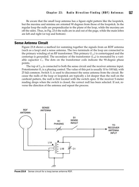
Practical_Antenna_Handbook_0071639586
514 P a r t V I : A n t e n n a s f o r O t h e r F r e q u e n c i e s Figure 23.3 Addition of sense antenna overcomes directional ambiguity of the loopstick. Figure 23.4 Cardioid pattern of sense-plus-loopstick antennas.
C h a p t e r 2 3 : R a d i o D i r e c t i o n - F i n d i n g ( R D F ) A n t e n n a s 515 Field Improvisation Suppose you are out in the woods trekking around the habitat of lions, tigers, and bears (plus a rattlesnake or two for good measure). Normally you find your way with a compass, a U.S. Geological Survey 7.5-min topological map, and a GPS receiver. Those little GPS marvels can usually give you excellent latitude and longitude indication when you can see sky above you, but often fail to deliver reliable position information in woodlands and dense forests. In such terrain, the answer to your direction-finding problem might be the little portable AM BCB radio (Fig. 23.5) that you brought along for company. Open the back of the radio and find the loopstick antenna, because you will need to know its orientation. In the radio shown in Fig. 23.5 the loopstick lies across the top of the radio, from left to right, but in other radios it is vertical, from top to bottom. Once you know its position, you can tune in a known AM station and orient the radio until you find a null. Next, point your compass in the same direction to obtain the numerical bearing (0–360°) of the signal. If you know the approximate location of the broadcast station, subtract the bearing you determined from 180 degrees (or vice versa, depending on which method gives you a positive value equal to 360 or less) and draw a line on the topo map at that angle, originating at the known AM broadcast station. Of course, it’s still a bidirectional indication, so all you know is the line along which you are lost. Now tune in a different station in a different city (or one at least far enough from the first station to make a difference) and take another reading. Again subtract (or add) 180 degrees to obtain a positive number between 0 and 360. Draw a line at this bearing originating from the second broadcast station location. These two lines should intersect at your approximate location. If you know the locations of additional broadcast stations, take a third, fourth, and fifth reading and you will generally be able to pinpoint your location pretty tightly. If you were smart enough to plan ahead, you will have se- Figure 23.5 AM portable radio. Dark bar represents position and direction of internal loopstick.
- Page 483 and 484: C h a p t e r 2 0 : M i c r o w a v
- Page 485 and 486: C h a p t e r 2 0 : M i c r o w a v
- Page 487 and 488: C h a p t e r 2 0 : M i c r o w a v
- Page 489 and 490: C h a p t e r 2 0 : M i c r o w a v
- Page 491 and 492: C h a p t e r 2 0 : M i c r o w a v
- Page 493 and 494: C h a p t e r 2 0 : M i c r o w a v
- Page 495 and 496: C h a p t e r 2 0 : M i c r o w a v
- Page 497 and 498: C h a p t e r 2 0 : M i c r o w a v
- Page 499 and 500: C h a p t e r 2 0 : M i c r o w a v
- Page 501 and 502: C h a p t e r 2 0 : M i c r o w a v
- Page 503 and 504: C h a p t e r 2 0 : M i c r o w a v
- Page 505 and 506: C h a p t e r 2 0 : M i c r o w a v
- Page 507 and 508: C h a p t e r 2 0 : M i c r o w a v
- Page 509 and 510: C h a p t e r 2 0 : M i c r o w a v
- Page 511 and 512: CHAPTER 21 Antenna Noise Temperatur
- Page 513 and 514: C h a p t e r 2 1 : A n t e n n a N
- Page 515 and 516: C h a p t e r 2 1 : A n t e n n a N
- Page 517 and 518: CHAPTER 22 Radio Astronomy Antennas
- Page 519 and 520: C h a p t e r 2 2 : R a d i o A s t
- Page 521 and 522: C h a p t e r 2 2 : R a d i o A s t
- Page 523 and 524: C h a p t e r 2 2 : R a d i o A s t
- Page 525 and 526: C h a p t e r 2 2 : R a d i o A s t
- Page 527 and 528: C h a p t e r 2 2 : R a d i o A s t
- Page 529 and 530: Figure 22.9 Interferometer pattern.
- Page 531 and 532: CHAPTER 23 Radio Direction-Finding
- Page 533: C h a p t e r 2 3 : R a d i o D i r
- Page 537 and 538: C h a p t e r 2 3 : R a d i o D i r
- Page 539 and 540: C h a p t e r 2 3 : R a d i o D i r
- Page 541 and 542: Figure 23.9 Adcock array RDF antenn
- Page 543 and 544: Figure 23.11 Watson-Watt Adcock arr
- Page 545 and 546: C h a p t e r 2 3 : R a d i o D i r
- Page 547 and 548: C h a p t e r 2 3 : R a d i o D i r
- Page 549 and 550: C h a p t e r 2 3 : R a d i o D i r
- Page 551 and 552: Tuning, Troubleshooting, and Design
- Page 553 and 554: CHAPTER 24 Antenna Tuners (ATUs) Th
- Page 555 and 556: C h a p t e r 2 4 : a n t e n n a T
- Page 557 and 558: C h a p t e r 2 4 : a n t e n n a T
- Page 559 and 560: C h a p t e r 2 4 : a n t e n n a T
- Page 561 and 562: C h a p t e r 2 4 : a n t e n n a T
- Page 563 and 564: C h a p t e r 2 4 : a n t e n n a T
- Page 565 and 566: CHAPTER 25 Antenna Modeling Softwar
- Page 567 and 568: C h a p t e r 2 5 : A n t e n n a M
- Page 569 and 570: C h a p t e r 2 5 : A n t e n n a M
- Page 571: Figure 25.3B Bent dipole wire and s
- Page 574 and 575: C h a p t e r 2 5 : A n t e n n a M
- Page 576 and 577: C h a p t e r 2 5 : A n t e n n a M
- Page 578 and 579: C h a p t e r 2 5 : A n t e n n a M
- Page 580 and 581: CHAPTER 26 The Smith Chart The math
- Page 582 and 583: Figure 26.2 Normalized impedance li
514 P a r t V I : A n t e n n a s f o r O t h e r F r e q u e n c i e s<br />
Figure 23.3 Addition of sense antenna overcomes directional ambiguity of the loopstick.<br />
Figure 23.4 Cardioid pattern of sense-plus-loopstick antennas.


