2.2. Circuitul de comand@ al tiristorului cu stingere pe poart@ (gril ...
2.2. Circuitul de comand@ al tiristorului cu stingere pe poart@ (gril ...
2.2. Circuitul de comand@ al tiristorului cu stingere pe poart@ (gril ...

Create successful ePaper yourself
Turn your PDF publications into a flip-book with our unique Google optimized e-Paper software.
24 Comanda dispozitivelor electronice <strong>de</strong> putere - 2<br />
<strong>2.2.</strong> <strong>Cir<strong>cu</strong>itul</strong> <strong>de</strong> <strong>comand@</strong> <strong>al</strong> <strong>tiristorului</strong> <strong>cu</strong> <strong>stingere</strong> <strong>pe</strong><br />
<strong>poart@</strong> (<strong>gril</strong>@) - GTO<br />
Tiristoarele tip GTO sunt dispozitive complet comandabile, în sensul<br />
c@ modificarea st@rii <strong>de</strong> conduc]ie (blocat/saturat) este re<strong>al</strong>izabil@ ^n ambele<br />
sensuri prin intermediul cir<strong>cu</strong>itului <strong>de</strong> <strong>poart@</strong>. Deschi<strong>de</strong>rea se ob]ine în mod<br />
similar <strong>cu</strong> tiristoarele obi}nuite, prin injectarea unui <strong>cu</strong>rent pozitiv în <strong>gril</strong>@ în<br />
raport <strong>cu</strong> catodul, consi<strong>de</strong>ra]iile f@<strong>cu</strong>te in paragraful 2.1 r@mânând în<br />
întregime v<strong>al</strong>abile.<br />
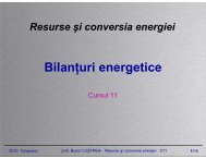
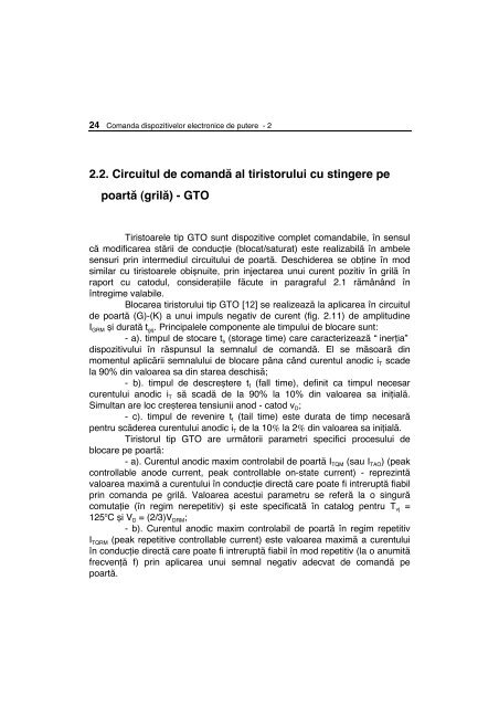
Blocarea <strong>tiristorului</strong> tip GTO [12] se re<strong>al</strong>izeaz@ la aplicarea în cir<strong>cu</strong>itul<br />
<strong>de</strong> <strong>poart@</strong> (G)-(K) a unui impuls negativ <strong>de</strong> <strong>cu</strong>rent (fig. 2.11) <strong>de</strong> amplitudine<br />
I GRM }i durat@ t gq. Princip<strong>al</strong>ele componente <strong>al</strong>e timpului <strong>de</strong> blocare sunt:<br />
- a). timpul <strong>de</strong> stocare t s (storage time) care caracterizeaz@ “ iner]ia”<br />
dispozitivului în r@spunsul la semn<strong>al</strong>ul <strong>de</strong> <strong>comand@</strong>. El se m@soar@ din<br />
momentul aplic@rii semn<strong>al</strong>ului <strong>de</strong> blocare pâna când <strong>cu</strong>rentul anodic i T sca<strong>de</strong><br />
la 90% din v<strong>al</strong>oarea sa din starea <strong>de</strong>schis@;<br />
- b). timpul <strong>de</strong> <strong>de</strong>scre}tere t f (f<strong>al</strong>l time), <strong>de</strong>finit ca timpul necesar<br />
<strong>cu</strong>rentului anodic i T s@ scad@ <strong>de</strong> la 90% la 10% din v<strong>al</strong>oarea sa ini]i<strong>al</strong>@.<br />
Simultan are loc cre}terea tensiunii anod - catod v D;<br />
- c). timpul <strong>de</strong> revenire t t (tail time) este durata <strong>de</strong> timp necesar@<br />
<strong>pe</strong>ntru sc@<strong>de</strong>rea <strong>cu</strong>rentului anodic i T <strong>de</strong> la 10% la 2% din v<strong>al</strong>oarea sa ini]i<strong>al</strong>@.<br />
Tiristorul tip GTO are urm@torii parametri s<strong>pe</strong>cifici procesului <strong>de</strong><br />
blocare <strong>pe</strong> <strong>poart@</strong>:<br />
- a). Curentul anodic maxim controlabil <strong>de</strong> <strong>poart@</strong> I TQM (sau I TAO) (<strong>pe</strong>ak<br />
controllable ano<strong>de</strong> <strong>cu</strong>rrent, <strong>pe</strong>ak controllable on-state <strong>cu</strong>rrent) - reprezint@<br />
v<strong>al</strong>oarea maxim@ a <strong>cu</strong>rentului ^n conduc]ie direct@ care poate fi intrerupt@ fiabil<br />
prin comanda <strong>pe</strong> <strong>gril</strong>@. V<strong>al</strong>oarea acestui parametru se refer@ la o singur@<br />
comuta]ie (în regim nere<strong>pe</strong>titiv) }i este s<strong>pe</strong>cificat@ în cat<strong>al</strong>og <strong>pe</strong>ntru T vj =<br />
125 o C }i V D = (2/3)V DRM;<br />
- b). Curentul anodic maxim controlabil <strong>de</strong> <strong>poart@</strong> în regim re<strong>pe</strong>titiv<br />
I TQRM (<strong>pe</strong>ak re<strong>pe</strong>titive controllable <strong>cu</strong>rrent) este v<strong>al</strong>oarea maxim@ a <strong>cu</strong>rentului<br />
în conduc]ie direct@ care poate fi intrerupt@ fiabil în mod re<strong>pe</strong>titiv (la o anumit@<br />
frecven]@ f) prin aplicarea unui semn<strong>al</strong> negativ a<strong>de</strong>cvat <strong>de</strong> <strong>comand@</strong> <strong>pe</strong><br />
<strong>poart@</strong>.
90%<br />
90% 10%<br />
0<br />
0<br />
IGRM<br />
iT<br />
iGR<br />
<strong>2.2.</strong> - <strong>Cir<strong>cu</strong>itul</strong> <strong>de</strong> <strong>comand@</strong> <strong>al</strong> <strong>tiristorului</strong> GTO 25<br />
<br />
<br />
diGR/dt<br />
ts<br />
tgq<br />
tf<br />
<br />
<br />
2%<br />
tt<br />
QGQ<br />
Fig. 2.11 Curentul prin tiristor }i ^n cir<strong>cu</strong>itul <strong>de</strong> <strong>comand@</strong> la blocare<br />
Având în ve<strong>de</strong>re faptul c@ la o func]ionare continu@ în regim <strong>de</strong> comutare<br />
pier<strong>de</strong>rile în dispozitiv cresc, ITQRM este <strong>de</strong> regul@ mult inferior (uneori chiar <strong>de</strong><br />
dou@ ori) <strong>cu</strong>rentului maxim ITQM; - c). Timpul <strong>de</strong> blocare tgq (}i componentele s<strong>al</strong>e) s<strong>pe</strong>cificat <strong>pe</strong>ntru un<br />
<strong>cu</strong>rent anodic eg<strong>al</strong> <strong>cu</strong> ITQRM, la o tem<strong>pe</strong>ratur@ a jonc]iunii Tvj =125 o C. (Se mai<br />
utilizeaz@ nota]iile tdq <strong>pe</strong>ntru ts, trq <strong>pe</strong>ntru tf }i ttq <strong>pe</strong>ntru tt); - d). Sarcina stocat@ QGQ reprezint@ v<strong>al</strong>oarea sarcinii electrice extrase<br />
din cir<strong>cu</strong>itul <strong>de</strong> <strong>poart@</strong> în <strong>de</strong><strong>cu</strong>rsul interv<strong>al</strong>ului tgq; - e). Factorul o<strong>pe</strong>ra]ion<strong>al</strong> <strong>de</strong> câ}tig în <strong>cu</strong>rent la blocare Goff (o<strong>pe</strong>ration<strong>al</strong> turn-off gain) <strong>de</strong>finit ca raportul dintre <strong>cu</strong>rentul anodic controlabil<br />
<strong>de</strong> <strong>poart@</strong> în mod re<strong>pe</strong>titiv }i amplitudinea <strong>cu</strong>rentului <strong>de</strong> <strong>gril</strong>@ (în gener<strong>al</strong> <strong>de</strong><br />
v<strong>al</strong>oare 3...10):<br />
TQRM<br />
G off =<br />
GRM<br />
I<br />
(<strong>2.2.</strong>1)<br />
I<br />
Timpii t s, t f }i t t sunt <strong>de</strong> regul@ men]iona]i <strong>pe</strong>ntru v<strong>al</strong>oarea s<strong>pe</strong>cificat@ a m@rimii<br />
G off. Odat@ <strong>cu</strong> cre}terea frecven]ei <strong>de</strong> comuta]ie se re<strong>comand@</strong> re<strong>al</strong>izarea<br />
bloc@rii (cât }i <strong>de</strong>schi<strong>de</strong>rea) <strong>cu</strong> ajutorul unor impulsuri <strong>de</strong> <strong>cu</strong>rent <strong>de</strong><br />
amplitudine ridicat@. O<strong>pe</strong>rarea la v<strong>al</strong>ori reduse <strong>al</strong>e câ}tigului G off prezint@<br />
avantajul unui timp redus <strong>de</strong> comuta]ie având ca efect minimizarea pier<strong>de</strong>rilor<br />
în acest regim.<br />
t<br />
t
26 Comanda dispozitivelor electronice <strong>de</strong> putere - 2<br />
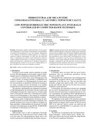
In fig. 2.12 sunt prezenta]i timpul <strong>de</strong> stocare t s }i <strong>cu</strong>rentul maxim <strong>de</strong><br />
<strong>gril</strong>@ func]ie <strong>de</strong> <strong>cu</strong>rentul anodic I TQ;<br />
- f). Factorul maxim <strong>de</strong> câ}tig în <strong>cu</strong>rent la blocare G off(max) (<strong>pe</strong>ak turnoff<br />
gain) <strong>de</strong>finit <strong>pe</strong>ntru v<strong>al</strong>oarea minim@ I GRMmin a amplitudinii <strong>cu</strong>rentului <strong>de</strong> <strong>gril</strong>@<br />
care mai poate asigura întreru<strong>pe</strong>rea <strong>cu</strong>rentului anodic i T (<strong>de</strong> regul@ i T=I TQRM).<br />
Utilizarea <strong>tiristorului</strong> tip GTO la un asemenea câ}tig conduce inerent la<br />
cre}terea timpului <strong>de</strong> blocare t gq în princip<strong>al</strong> datorit@ cre}terii componentei <strong>de</strong><br />
stocare t s;<br />
- g). Tensiunea invers@ maxim@ <strong>de</strong> <strong>poart@</strong> V GRM (<strong>pe</strong>ak reverse gate<br />
voltage) este v<strong>al</strong>oarea maxim@ a tensiunii negative aplicat@ între <strong>poart@</strong> }i<br />
catod în ve<strong>de</strong>rea bloc@rii <strong>tiristorului</strong> tip GTO. Ea este limitat@ <strong>de</strong> tensiunea <strong>de</strong><br />
str@pungere în av<strong>al</strong>an}@ BV GK (în gener<strong>al</strong> <strong>de</strong> ordinul 7...20V);<br />
- h). Rata <strong>de</strong> cre}tere a <strong>cu</strong>rentului invers <strong>de</strong> <strong>poart@</strong> di GR/dt [A/ms]<br />
(rate of rise of reverse gate <strong>cu</strong>rrent) reprezint@ viteza <strong>de</strong> cre}tere cvasi-liniar@<br />
a <strong>cu</strong>rentului negativ <strong>de</strong> <strong>gril</strong>@ <strong>de</strong> la v<strong>al</strong>oarea zero la i GR=I GRM. O v<strong>al</strong>oare mai<br />
mare a acesteia conduce la mic}orarea interv<strong>al</strong>ului t s }i <strong>de</strong>ci a timpului <strong>de</strong><br />
blocare a dispozitivului. V<strong>al</strong>orile tipice <strong>al</strong>e acestei varia]ii sunt <strong>cu</strong>prinse între<br />
1A/µs si 30A/µs.<br />
ts[µs]<br />
30<br />
25<br />
20<br />
15<br />
10<br />
5<br />
0<br />
diGR/dt=30A/µs<br />
Tvj=125°C<br />
IGRM<br />
ts<br />
IGRM [A]<br />
600<br />
500<br />
400<br />
300<br />
200<br />
100<br />
500 1000 1500 2000 ITQ [A]<br />
Fig. 2.12 Timpul <strong>de</strong> stocare }i <strong>cu</strong>rentul maxim <strong>de</strong> blocare func]ie <strong>de</strong> <strong>cu</strong>rentul anodic.
<strong>2.2.</strong> - <strong>Cir<strong>cu</strong>itul</strong> <strong>de</strong> <strong>comand@</strong> <strong>al</strong> <strong>tiristorului</strong> GTO 27<br />
In mod similar tiristoarelor obi}nuite, tiristorul tip GTO prezint@ o<br />
caracteristic@ <strong>de</strong> <strong>poart@</strong> <strong>pe</strong>ntru comanda <strong>de</strong>schi<strong>de</strong>rii (în cadranul I) }i o a doua<br />
caracteristic@ <strong>de</strong> <strong>poart@</strong> <strong>pe</strong>ntru blocare (în cadranul III) limitat@ <strong>de</strong> acelea}i<br />
m@rimi (dis<strong>pe</strong>rsia caracteristicilor, tem<strong>pe</strong>ratura }i puterea disipat@ maxim@ în<br />
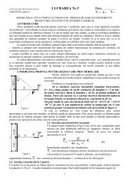
cir<strong>cu</strong>itul <strong>de</strong> <strong>poart@</strong> la blocare PRGM). Principi<strong>al</strong> structura unui cir<strong>cu</strong>it <strong>de</strong> <strong>comand@</strong> în <strong>gril</strong>@ a <strong>tiristorului</strong> tip<br />
GTO este prezentat@ ^n fig. 2.13. Alimentarea este asigurat@ <strong>de</strong> o surs@ dubl@<br />
<strong>de</strong> tensiune (+VCC, -VCC) care genereaz@, <strong>cu</strong> ajutorul tranzistoarelor T1 }i T2 (<strong>cu</strong> func]ionare în contratimp) }i rezisten]elor a R11, R12 }i R2, <strong>cu</strong>ren]ii necesari<br />
<strong>comand@</strong>rii <strong>de</strong>schi<strong>de</strong>rii sau bloc@rii dispozitivului. Con<strong>de</strong>nsatorul C1 re<strong>al</strong>izeaz@<br />
supracre}terea <strong>cu</strong>rentului <strong>de</strong> <strong>comand@</strong> la <strong>de</strong>schi<strong>de</strong>re.<br />
O <strong>al</strong>t@ schem@ <strong>de</strong> principiu, care utilizeaz@ o singur@ surs@ <strong>de</strong><br />
<strong>al</strong>imentare, se compune <strong>de</strong> asemenea din cele dou@ tranzistoare <strong>cu</strong><br />
rezisten]ele aferente, sursa <strong>de</strong> tensiune negativ@ necesar@ bloc@rii fiind<br />
re<strong>al</strong>izat@ <strong>cu</strong> ajutorul con<strong>de</strong>nsatorului C a c@rui tensiune este limitat@ <strong>de</strong> dioda<br />
Zener DZ (fig. 2.14).<br />
Inc@rcarea con<strong>de</strong>nsatorului se re<strong>al</strong>izeaz@ la comanda <strong>de</strong>schi<strong>de</strong>rii<br />
(aplicând un impuls <strong>de</strong> <strong>comand@</strong> corespunz@tor <strong>pe</strong> baza tranzistorului T1), <strong>cu</strong>rentul pozitiv <strong>de</strong> <strong>poart@</strong> fiind dat <strong>de</strong> expresia:<br />
CC CE1 c GK<br />
i GF(t)<br />
=<br />
1<br />
V - V - v (t) - V<br />
(<strong>2.2.</strong>2)<br />
R<br />
comand<br />
on<br />
off<br />
R<br />
R12<br />
R2<br />
T1<br />
T2<br />
-VCC<br />
R11<br />
C1<br />
GTO<br />
+VCC<br />
Fig. 2.13 Schema cir<strong>cu</strong>itului <strong>de</strong> <strong>comand@</strong> în <strong>gril</strong>@ a <strong>tiristorului</strong> GTO<br />
<strong>cu</strong> dou@ surse <strong>de</strong> <strong>al</strong>imentare.
28 Comanda dispozitivelor electronice <strong>de</strong> putere - 2<br />
comanda<br />
on<br />
off<br />
R<br />
R1<br />
T1<br />
R2<br />
+VCC<br />
vCE1<br />
T2<br />
C<br />
DZ<br />
vc(t)<br />
vGK<br />
GTO<br />
Fig. 2.14 Comanda <strong>tiristorului</strong> GTO <strong>cu</strong> o singur@ surs@ <strong>de</strong> <strong>al</strong>imentare.<br />
Supracre}terea <strong>cu</strong>rentului <strong>de</strong> <strong>comand@</strong> la <strong>de</strong>schi<strong>de</strong>re se re<strong>al</strong>izeaz@<br />
implicit <strong>pe</strong> durata înc@rc@rii con<strong>de</strong>nsatorului C.<br />
Când <strong>pe</strong> cir<strong>cu</strong>itul comun <strong>de</strong> baz@ <strong>al</strong> tranzistoarelor T 1 }i T 2 se aplic@<br />
impulsul <strong>de</strong> <strong>comand@</strong> <strong>al</strong> bloc@rii <strong>tiristorului</strong> GTO (care are ca efect<br />
<strong>de</strong>schi<strong>de</strong>rea lui T 2 }i blocarea lui T 1), se produce <strong>de</strong>sc@rcarea con<strong>de</strong>nsatorului<br />
C <strong>pe</strong> cir<strong>cu</strong>itul <strong>de</strong> <strong>poart@</strong>, <strong>cu</strong>rentul <strong>de</strong> <strong>de</strong>sc@rcare comandând astfel comuta]ia.<br />
Con<strong>de</strong>nsatorul C se dimensioneaz@ astfel încât sarcina <strong>pe</strong> care o a<strong>cu</strong>muleaz@<br />
la <strong>de</strong>schi<strong>de</strong>rea <strong>tiristorului</strong> GTO s@ poat@ produce blocarea:<br />
C > Q<br />
V<br />
GQ<br />
DZ<br />
IGRM ts<br />
ITQRM ts<br />
≈ = (<strong>2.2.</strong>3)<br />
V DZ Goff VDZ<br />
Stingerea <strong>tiristorului</strong> GTO reprezint@ procesul cel mai dificil <strong>de</strong><br />
re<strong>al</strong>izat din cauza nivelelor <strong>de</strong> <strong>cu</strong>rent în <strong>gril</strong>@ }i a ratei <strong>de</strong> cre}tere relativ mari<br />
<strong>al</strong>e acestuia la blocare. Din acest motiv este <strong>de</strong>osebit <strong>de</strong> important@<br />
im<strong>pe</strong>dan]a sursei negative <strong>de</strong> <strong>al</strong>imentare -V CC }i, în gener<strong>al</strong>, a cir<strong>cu</strong>itului <strong>de</strong><br />
<strong>stingere</strong>. O v<strong>al</strong>oare mic@ a acesteia se re<strong>al</strong>izeaz@ practic prin dispunerea <strong>de</strong><br />
con<strong>de</strong>nsatoare <strong>de</strong> <strong>de</strong><strong>cu</strong>plare în apropierea dispozitivelor implicate în<br />
comandarea bloc@rii, s<strong>cu</strong>rtarea la minim a conductoarelor <strong>de</strong> leg@tur@ pre<strong>cu</strong>m<br />
}i prin utilizarea unor comutatoare statice (T 2) <strong>pe</strong>rformante (tiristoare rapi<strong>de</strong>,<br />
tranzistoare bipolare <strong>de</strong> comuta]ie sau MOS). In acela}i scop, în unele<br />
aplica]ii se înlo<strong>cu</strong>ie}te rezisten]a R 2 <strong>cu</strong> o inductivitate prin intermediul c@reia<br />
se impune panta <strong>cu</strong>rentului <strong>de</strong> blocare.