Cilindro iso, dupla ação (ra/8000/m) - Coppi
Cilindro iso, dupla ação (ra/8000/m) - Coppi
Cilindro iso, dupla ação (ra/8000/m) - Coppi
- No tags were found...

Create successful ePaper yourself
Turn your PDF publications into a flip-book with our unique Google optimized e-Paper software.
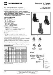
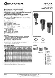
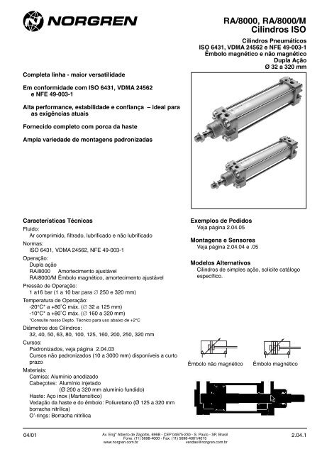
Completa linha - maior versatilidadeRA/<strong>8000</strong>, RA/<strong>8000</strong>/M<strong>Cilindro</strong>s ISO<strong>Cilindro</strong>s PneumáticosISO 6431, VDMA 24562 e NFE 49-003-1Êmbolo magnético e não magnéticoDupla AçãoØ 32 a 320 mmEm conformidade com ISO 6431, VDMA 24562e NFE 49-003-1Alta performance, estabilidade e confiança – ideal pa<strong>ra</strong>as exigências atuaisFornecido completo com porca da hasteAmpla variedade de montagens padronizadasCa<strong>ra</strong>cterísticas TécnicasFluido:Ar comprimido, filt<strong>ra</strong>do, lubrificado e não lubrificadoNormas:ISO 6431, VDMA 24562, NFE 49-003-1Ope<strong>ra</strong>ção:Dupla açãoRA/<strong>8000</strong> Amortecimento ajustávelRA/<strong>8000</strong>/M Êmbolo magnético, amortecimento ajustávelPressão de Ope<strong>ra</strong>ção:1 a16 bar (1 a 10 bar pa<strong>ra</strong> ∅ 250 e 320 mm)Tempe<strong>ra</strong>tu<strong>ra</strong> de Ope<strong>ra</strong>ção:-20°C* a +80˚C máx. (∅ 32 a 125 mm)-10°C* a +80˚C máx. (∅ 160 a 320 mm)*Consulte nosso Depto. Técnico pa<strong>ra</strong> uso abaixo de +2°CDiâmetros dos <strong>Cilindro</strong>s:32, 40, 50, 63, 80, 100, 125, 160, 200, 250, 320 mmCursos:Padronizados, veja página 2.04.03Cursos não padronizados (10 a 3000 mm) disponíveis a curtop<strong>ra</strong>zoMateriais:Camisa: Alumínio anodizadoCabeçotes: Alumínio injetado(Ø 200 a 320 mm alumínio fundido)Haste: Aço inox (Martensítico)Vedação da haste e do êmbolo: Poliuretano (Ø 125 a 320 mmbor<strong>ra</strong>cha nitrílica)O’-rings: Bor<strong>ra</strong>cha nitrílicaExemplos de PedidosVeja página 2.04.05Montagens e SensoresVeja página 2.04.04 e .05Modelos Alternativos<strong>Cilindro</strong>s de simples ação, solicite catálogoespecífico.Êmbolo não magnéticoÊmbolo magnético04/01Av. Engº Alberto de Zagottis, 696B - CEP 04675-230 - S. Paulo - SP, B<strong>ra</strong>silFone: (11) 5698-4000 - Fax: (11) 5698-4001/4015www.norgren.com.brvendas@norgren.com.br2.04.1
<strong>Cilindro</strong>s OpcionaisSímbolo Modelo Símbolo Modelo Descrição Dimensõesêmbolo não magnético êmbolo magnético PáginaRA/<strong>8000</strong> RA/<strong>8000</strong>/M <strong>Cilindro</strong> padrão 6CA/<strong>8000</strong> CA/<strong>8000</strong>/M <strong>Cilindro</strong> com haste de pistão com cromo duro 6SA/<strong>8000</strong> SA/<strong>8000</strong>/M <strong>Cilindro</strong> com haste de aço inox (Austenítico) 6RA/<strong>8000</strong>/W1 RA/<strong>8000</strong>/W2 <strong>Cilindro</strong> com limpador/vedação de haste especial (adequado pa<strong>ra</strong> 6aplicações com cimento, gesso (reboco), areia ou gelo (∅ 32 a 125 mm)RA/<strong>8000</strong>/X1 RA/<strong>8000</strong>/X2 <strong>Cilindro</strong>s de baixo atrito (∅ 32 a 200 mm) 6Fluido: Ar comprimido, recomendado filt<strong>ra</strong>do e não lubrificado(1 a 10 bar)TRA/<strong>8000</strong> TRA/<strong>8000</strong>/M <strong>Cilindro</strong>s com vedação pa<strong>ra</strong> alta tempe<strong>ra</strong>tu<strong>ra</strong> (150˚C máx.) 6RA/<strong>8000</strong>/IU RA/<strong>8000</strong>/MU <strong>Cilindro</strong> com extensão da haste 6RA/<strong>8000</strong>/W5 RA/<strong>8000</strong>/W6 <strong>Cilindro</strong> com extensão da haste e limpador/vedação especial (adequado 6pa<strong>ra</strong> aplicações com cimento, gesso (reboco), areia ou gelo)(∅ 32 a 125 mm).RA/<strong>8000</strong>/G RA/<strong>8000</strong>/MG <strong>Cilindro</strong> com sanfona de proteção da haste 8TRA/<strong>8000</strong>/G TRA/<strong>8000</strong>/MG <strong>Cilindro</strong> com sanfona e vedações pa<strong>ra</strong> alta tempe<strong>ra</strong>tu<strong>ra</strong> (150˚C máx.)RA/<strong>8000</strong>/W RA/<strong>8000</strong>/MW <strong>Cilindro</strong> sem amortecimento 6RA/<strong>8000</strong>/X3 RA/<strong>8000</strong>/X4 <strong>Cilindro</strong> de baixo atrito sem amortecimento (∅ 32 a 200 mm) 6Fluido: Ar comprimido, recomendado filt<strong>ra</strong>do e não lubrificado(1 a 10 bar)HRA/<strong>8000</strong>/M <strong>Cilindro</strong> com vedação hidráulica (∅ 32 a 100 mm) 6RA/<strong>8000</strong>/J RA/<strong>8000</strong>/JM <strong>Cilindro</strong> com haste <strong>dupla</strong> 7RA/<strong>8000</strong>/W3 RA/<strong>8000</strong>/W4 <strong>Cilindro</strong> com haste <strong>dupla</strong> e limpador/vedação especial (adequado pa<strong>ra</strong> 6aplicações com cimento, gesso (reboco), areia ou gelo)(∅ 32 a 125 mm)RA/<strong>8000</strong>/IT RA/<strong>8000</strong>/MT <strong>Cilindro</strong> geminado quatro posições (∅ 32 a 200 mm) 7RA/<strong>8000</strong>/N1 RA/<strong>8000</strong>/N2 <strong>Cilindro</strong> com haste anti-giro (∅ 32 a 100 mm) 7RA/<strong>8000</strong>/L2 RA/<strong>8000</strong>/L4 <strong>Cilindro</strong> com unidade de t<strong>ra</strong>va (PASSIVA). O t<strong>ra</strong>vamento é obtido pela força 8da mola na remoção do sinal pa<strong>ra</strong> a unidade. Pressão de Ope<strong>ra</strong>çãopa<strong>ra</strong> unidade de t<strong>ra</strong>vamento: 4 a 10 barRA/<strong>8000</strong>/P1 a P8 <strong>Cilindro</strong> com extensão da haste 9 + 10Ope<strong>ra</strong>ção: O (eletro-) posicionador pneumático é usado pa<strong>ra</strong> ope<strong>ra</strong><strong>ra</strong>tuadores at<strong>ra</strong>vés dos controles elétrico/pneumáticos com uma saídaanalógica.Posicionadores:Posicionadores Eletro-Pneumáticos*:Tipo: FOXBORO/ECKARDT, tipo básico SRI 986SIEMENS, tipos básicos 6DR3000-•N/E, 6DR4000-•N/EPosicionador Pneumático*:Tipo: FOXBORO/ECKARDT, tipo-básico SRP 981* Consulte nosso Depto. Técnico pa<strong>ra</strong> ca<strong>ra</strong>cterísticas técnicasPressão de Ope<strong>ra</strong>ção: 2 a 6 barDiâmetros dos <strong>Cilindro</strong>s: 63, 80, 100, 125, 160, 200, 250, 320 mmComprimentos do Curso: 100 a 600 mmAtenção: A força utilizável pa<strong>ra</strong> cilindros RA/<strong>8000</strong>/P1 a /P8 é 50%, daforça teórica.Pa<strong>ra</strong> combinações dos cilindros opcionais consulte nosso Depto. Técnico.2.04.2Av. Engº Alberto de Zagottis, 696B - CEP 04675-230 - S. Paulo - SP, B<strong>ra</strong>silFone: (11) 5698-4000 - Fax: (11) 5698-4001/4015www.norgren.com.brvendas@norgren.com.br04/01
Códigos✶✶A/8✶✶✶/✶✶/✶✶✶✶Alternativas especiaisSubstituir porVedações pa<strong>ra</strong> altas tempe<strong>ra</strong>tu<strong>ra</strong>s, +150°C máx. TMaterial da HasteAço inox (Martensítico)Aço com cromo duroaço inox (Austenítico)Substituir porRCSRoscasSubstituir porMétrica Orifícios: ISO 228 (G 1/8 a G 1) ASériesSubstituir por<strong>8000</strong> 8Diâmetros dos <strong>Cilindro</strong>s (mm)Substituir por032, 040, 050, 063, 080, 100, 125, 160, 200, 250, 320Alternativas (êmbolo magnético) Substituir porPadrãoMLimpador/vedação especialW2Baixo atritoX2Extensão da hasteMUExtensão da haste, limpador/vedação especial W6Haste com sanfonaMGSem amortecimentoMWSem amortecimento, baixo atritoX4Haste <strong>dupla</strong>JMHaste <strong>dupla</strong>, limpador/vedação especiaW4Geminado, 4 posiçõesMTHaste anti-giroN2Unidade de t<strong>ra</strong>vamentoL4Nota: Se não for definida a opção, desconside<strong>ra</strong>r a posição dentro do código, ex.: RA/8100/100.Pa<strong>ra</strong> combinações de cilindros opcionais, consulte nosso Depto. Técnico.Cursos (mm)3000 max.Alternativas (êmbolo não magnético) Substituir porPadrãoLimpador/vedação especialW1Baixo atritoX1Extensão da hasteIUExtensão da haste, Limpador/vedação especial W5Haste com sanfonaGSem amortecimnetoWSem amortecimento, baixo atritoX3Haste <strong>dupla</strong>JHaste <strong>dupla</strong>, Limpador/vedação especialW3Geminado - 4 posiçõesITHaste anti-giroN1Unidade de t<strong>ra</strong>vamentoL2<strong>Cilindro</strong> com posicionador FOXBORO, lado esquerdo# P1<strong>Cilindro</strong> com posicionador FOXBORO, lado esquerdo## P2<strong>Cilindro</strong> com posicionador FOXBORO, lado direito# P3<strong>Cilindro</strong> com posicionador FOXBORO, lado direito## P4<strong>Cilindro</strong> com posicionador SIEMENS, lado esquerdo# P5<strong>Cilindro</strong> com posicionador SIEMENS, lado esquerdo## P6<strong>Cilindro</strong> com posicionador SIEMENS, lado direito# P7<strong>Cilindro</strong> com posicionador SIEMENS, lado direito## P8# ação direta, ## ação reversaCursos Padronizados<strong>Cilindro</strong> Cursos (mm)∅ 25 50 80 100 125 160 200 250 320 400 50032 ● ● ● ● ● ● ● ● ● ● ●40 ● ● ● ● ● ● ● ● ● ● ●50 ● ● ● ● ● ● ● ● ● ● ●63 ● ● ● ● ● ● ● ● ● ● ●80 ● ● ● ● ● ● ● ● ● ● ●100 ● ● ● ● ● ● ● ● ● ● ●125 ● ● ● ● ● ● ● ● ● ● ●160 ● ● ● ● ● ● ● ● ● ● ●200 ● ● ● ● ● ● ● ● ● ● ●250 ● ● ● ● ● ● ● ● ● ● ●320 ● ● ● ● ● ● ● ● ● ● ●04/01 2.04.3Av. Engº Alberto de Zagottis, 696B - CEP 04675-230 - S. Paulo - SP, B<strong>ra</strong>silFone: (11) 5698-4000 - Fax: (11) 5698-4001/4015www.norgren.com.brvendas@norgren.com.br
MontagensEstilo ‘A’ Estilo ‘AK’ Estilo ‘B’, ‘G’ Estilo ‘C’ Estilo ‘D’ Estilo ‘D2’ Estilo ‘F’ Estilo ‘FH’ Estilo ‘H’<strong>Cilindro</strong>∅ Pág. 11 Pág. 17 Pág. 11 Pág. 11 Pág. 13 Pág. 14 Pág. 12 Pág. 16 Pág. 1632 QM/8032/35 QM/8025/38 QA/8032/22 QA/8032/21 QA/8032/23 QA/8032/42 QM/8025/25 QA/8032/34 QA/8032/2840 QM/8032/35 QM/8040/38 QA/8040/22 QA/8040/21 QA/8040/23 QA/8040/42 QM/8040/25 QA/8040/34 QA/8040/2850 QM/8050/35 QM/8050/38 QA/8050/22 QA/8050/21 QA/8050/23 QA/8050/42 QM/8050/25 QA/8050/34 QA/8050/2863 QM/8050/35 QM/8050/38 QA/8063/22 QA/8063/21 QA/8063/23 QA/8063/42 QM/8050/25 QA/8063/34 QA/8063/2880 QM/8080/35 QM/8080/38 QA/8080/22 QA/8080/21 QA/8080/23 QA/8080/42 QM/8080/25 QA/8080/34 QA/8080/28100 QM/8080/35 QM/8080/38 QA/8100/22 QA/8100/21 QA/8100/23 QA/8100/42 QM/8080/25 QA/8100/34 QA/8100/28125 QM/8125/35 QM/8125/38 QM/8125/22 QM/8125/21 QM/8125/23 QA/8125/42 QM/8125/25 QA/8125/34 QM/8125/28160 QM/8160/35 QM/8160/38 QM/8160/22 QM/8160/21 QM/8160/23 QA/8160/42 QM/8160/25 — QM/8160/28200 QM/8160/35 QM/8160/38 QM/8200/22 QM/8200/21 QM/8200/23 QA/8200/42 QM/8160/25 — QM/8200/28250 QM/8250/35 — QM/8250/22 QM/8250/21 QM/8250/23 — QM/8250/25 — QM/8250/28320 QM/8320/35 — QM/8320/22 QM/8320/21 QM/8320/23 — QM/8320/25 — QM/8320/28Estilo ‘L’ Estilo ‘M’ Estilo ‘R’ Estilo ‘S’ Estilo ‘SS’ Estilo ‘SW’ Estilo ‘UF’ Estilo ‘UH’ Estilo ‘UL’<strong>Cilindro</strong>∅ Pág. 13 Pág. 12 Pág. 15 Pág. 16 Pág. 12 Pág. 13 Pág. 17 Pág. 16 Pág. 1432 QA/8032/24 QM/8032/26 QA/8032/27 QA/8032/41 M/P19931 M/P19493 QM/8025/32 QA/8032/40 QA/8032/4340 QA/8040/24 QM/8040/26 QA/8040/27 QA/8040/41 M/P19932 M/P19494 QM/8040/32 QA/8040/40 QA/8040/4350 QA/8050/24 QM/8050/26 QA/8050/27 QA/8040/41 M/P19933 M/P19495 QM/8050/32 QA/8050/40 QA/8050/4363 QA/8063/24 QM/8063/26 QA/8063/27 QA/8063/41 M/P19934 M/P19496 QM/8050/32 QA/8063/40 QA/8063/4380 QA/8080/24 QM/8080/26 QA/8080/27 QA/8063/41 M/P19935 M/P19497 QM/8080/32 QA/8080/40 QA/8080/43100 QA/8100/24 QM/8100/26 QA/8100/27 QA/8100/41 M/P19936 M/P19498 QM/8080/32 QA/8100/40 QA/8100/43125 QM/8125/24 QM/8125/26 QM/8125/27 QA/8100/41 M/P19937 M/P19499 QM/8125/32 QA/8125/40 QA/8125/43160 QM/8160/24 QM/8160/26 QM/8160/27 QA/8160/41 M/P19938 M/P19679 QM/8160/32 QA/8160/40 QA/8160/43200 QM/8200/24 QM/8200/26 QM/8200/27 QA/8160/41 M/P19939 M/P19683 QM/8160/32 QA/8200/40 QA/8200/43250 QM/8250/24 — — — — M/P19446 QM/8250/32 — —320 QM/8320/24 — — — — M/P19447 QM/8320/32 — —Estilo ‘UR’ Estilo ‘US’ Blocos Guia Blocos Guia ** Unidade de *** Suporte pa<strong>ra</strong> Suporte pa<strong>ra</strong> Suporte pa<strong>ra</strong>T<strong>ra</strong>vamento Sensores # Sensores ## Sensores ###<strong>Cilindro</strong>∅ Pág. 15 Pág. 14 Pág. 20 Pág. 18 Pág. 8 Pág. 21 Pág. 21 Pág. 2132 QA/8032/33 M/P40310 QA/8032/51/* QA/8032/61/* QA/8032/59 QM/27/2/1 QM/31/032/22 QM/140/010/2240 QA/8040/33 M/P40311 QA/8040/51/* QA/8040/61/* QA/8040/59 QM/27/2/1 QM/31/032/22 QM/140/010/2250 QA/8050/33 M/P40312 QA/8050/51/* QA/8050/61/* QA/8050/59 QM/27/2/1 QM/31/032/22 QM/140/010/2263 QA/8063/33 M/P40313 QA/8063/51/* QA/8063/61/* QA/8063/59 QM/27/2/1 QM/31/032/22 QM/140/010/2280 QA/8080/33 M/P40314 QA/8080/51/* QA/8080/61/* QA/8080/59 QM/27/2/1 QM/31/080/22 QM/140/010/22100 QA/8100/33 M/P40315 QA/8100/51/* QA/8100/61/* QA/8100/59 QM/27/2/1 QM/31/080/22 QM/140/010/22125 QM/8125/33 M/P71355 — — QA/8125/59 QM/27/2/1 QM/31/080/22 —160 QM/8160/33 M/P71356 — — — QM/27/2/1 QM/31/160/22 —200 QM/8200/33 M/P71357 — — — QM/27/2/1 QM/31/160/22 —250 QM/8250/33 — — — — — QM/31/250/22 —320 QM/8320/33 — — — — — QM/31/320/22 —# M/50 ## QM/32 ### QM/140* Incluir comprimento do curso padronizado (50, 100, 160, 200, 250, 320, 400, ou 500) em mm. Consulte nosso Depto. Técnico pa<strong>ra</strong> cursos acima de 500 mm** Pa<strong>ra</strong> Cartucho de T<strong>ra</strong>va veja página 18*** Pa<strong>ra</strong> Cartucho de T<strong>ra</strong>va veja página 82.04.4Av. Engº Alberto de Zagottis, 696B - CEP 04675-230 - S. Paulo - SP, B<strong>ra</strong>silFone: (11) 5698-4000 - Fax: (11) 5698-4001/4015www.norgren.com.brvendas@norgren.com.br04/01
SensoresModeloReed M/50/LSU/.. M/50/LSU/CP QM/34 QM/34/P QM/31 QM/32 QM/32/P —M/50/RAC/5V —Estado Sólido M/50/EAP/.. M/50/EAP/CP — — — — — —M/50/EAN/.. M/50/EAN/CPPneumático — — — — — — — QM/140Modelo Voltagem Corrente Tempe<strong>ra</strong>tu<strong>ra</strong> LED Ca<strong>ra</strong>cterísticas Compr. Tipo Cabo Plug-in CatálogoReed Estado Sólido V c.a. V c.c. Máx. °C Cabo Cabo Reto 90° PáginaM/50/LSU/**V — 10 a 240 10 a 170 180 mA -20° a +80° ● — 2, 5, 10 m PVC 2 x 0,25 — — 2.21.1M/50/LSU/5U — 10 a 240 10 a 170 180 mA -20° a +80° ● — 5 m PUR 2 x 0,25 — — 2.21.1M/50/RAC/5V — 10 a 240 10 a 170 180 mA -20° a +80° — Inversor 5 m PVC 3 x 0,25 — — 2.20.1M/50/LSU/CP — 10 a 60 10 a 75 180 mA -20° a +80° ● Plug M8x1 5 m — M/P73001/5 — 2.20.1— M/50/EAP/**V — 10 a 30 150 mA -20° a +80° ● PNP 2, 5, 10 m PVC 3 x 0,25 — — 2.21.1— M/50/EAP/CP — 10 a 30 150 mA -20° a +80° ● PNP, plug M8x1 5 m — M/P73001/5 — 2.21.1— M/50/EAN/**V — 10 a 30 150 mA -20° a +80° ● NPN 2, 5, 10 m PVC 3 x 0,25 — — 2.21.1— M/50/EAN/CP — 10 a 30 150 mA -20° a +80° ● NPN, plug M8x1 5 m — M/P73001/5 — 2.21.1QM/31/C/** — 10 a 110 10 a 175 0,25 A -20° a +80° — Inversor 5 m PVC 3 x 0,5 — — 2.22.1QM/32/** — 10 a 240 10 a 240 1 A -20° a +80° ● — 2, 5, 10 m PVC 2 x 0,75 — — 2.22.1QM/32/P — 10 a 240 10 a 240 1 A -20° a +80° ● — 5 m PVC 3 x 0,34 M/P34692/5 — 2.22.1QM/33/C/** — 10 a 110 10 a 175 0,25 A -20° a +80° — Inversor 5 m PVC 2 x 0,34 — — 2.22.1QM/34/** — — 10 a 30 1 A -20° a +80° ● Saída: Positiva 2, 5, 10 m PVC 3 x 0,34 — — 2.22.1QM/34/P — — 10 a 30 1 A -20° a +80° ● Saída: Positiva 5 m PVC 3 x 0,25 M/P34614/5 M/P34615/5 2.22.1Pneumático Pressão de Ope<strong>ra</strong>ção Vazão Orifício Tempe<strong>ra</strong>tu<strong>ra</strong> Ponto Ativo Conexões Catálogo pág.QM/140 2 a 6 bar 40 l/min 2 mm +60 °C ● Pa<strong>ra</strong> tubo ø int. 3 mm 2.21.1** Incluir comprimento do cabo.Informações completas dos sensores (ca<strong>ra</strong>cterísticas técnicas, materiais dos cabos, dimensões, etc.) consulte catálogo específico.Exemplos pa<strong>ra</strong> Pedidos<strong>Cilindro</strong>sPa<strong>ra</strong> solicitar um cilindro padrão de 80 mm com êmbolomagnético e 50 mm de curso, especifique:RA/8080/M/50MontagensPa<strong>ra</strong> solicitar uma flange diantei<strong>ra</strong> montagem estilo ‘G’pa<strong>ra</strong> cilindro de 80 mm, especifique: QA/8080/22SensoresPa<strong>ra</strong> solicitar um sensor reed com LED e 2 m de cabo,especifique: M/50/LSU/2VSuportes pa<strong>ra</strong> SensoresPa<strong>ra</strong> solicitar um suporte pa<strong>ra</strong> sensor magnéticoM/50/LSU/2V; diâmetro do cilindro de 80 mm, especifique:QM/27/2/104/01 2.04.5Av. Engº Alberto de Zagottis, 696B - CEP 04675-230 - S. Paulo - SP, B<strong>ra</strong>silFone: (11) 5698-4000 - Fax: (11) 5698-4001/4015www.norgren.com.brvendas@norgren.com.br
Forças Teóricas ● Amortecimento ● Consumo de ArForças teóricas (N) a 6 bar Compr. amortecedor Volume inicial do Consumo de ar (l/cm de curso)a 6bar<strong>Cilindro</strong> ∅ Avanço Retorno (mm) amortecedor (cm 3 ) Avanço Retorno32 482 414 19 12,3 0,056 0,04840 754 633 22 20,7 0,088 0,07450 1178 990 24 36 0,137 0,11463 1870 1680 24 64 0,218 0,19580 3016 2722 27 116 0,35 0,32100 4710 4416 34 242 0,55 0,51125 7363 6882 41 451 0,86 0,79160 12064 11310 45 816 1,41 1,32200 18840 18090 45 1324 2,20 2,10250 29436 28236 60 2900 3,44 3,30320 48228 47292 65 5200 5,63 5,41Dimensões BásicasRA/<strong>8000</strong>, RA/<strong>8000</strong>/M — <strong>Cilindro</strong>s PadrãoAWHL8 + cursoCorte A - BAMKWL 2VDL 12PLGEEPa<strong>ra</strong>fuso doamortecedorGPLEEVAERø B e 11KKAPø BA e 11MM h 9KVSW (A/F)L 9BGRTBHBRTBHø 80 a 320 mmBG<strong>Cilindro</strong> ∅ AM AP ∅ B e11 ∅ BA e11 BG BH (A/F) ❑ E EE G KK KV (A/F) KW L232 22 3,5 30 30 18 6 47 G 1/8 27,5 M10x1,25 17 5 2040 24 4,5 35 35 18 6 53 G 1/4 32 M12x1,25 19 6 2250 32 6 40 40 18 8 65 G 1/4 31 M16x1,5 24 8 2763 32 10 45 45 17,5 8 75 G 3/8 33 M16x1,5 24 8 2980 40 8,5 45 45 21,5 19 95 G 3/8 33 M20x1,5 30 10 33100 40 9 55 55 21,5 19 115 G 1/2 37 M20x1,5 30 10 36125 54 10 60 60 30 24 140 G 1/2 46 M27x2 41 13,5 45160 72 18 65 65 28,5 32 183,5 G 3/4 50 M36x2 55 18 58200 72 18 75 75 28,5 32 224 G 3/4 50 M36x2 55 18 67250 84 22,5 90 90 35 36 280 G 1 58 M42x2 65 21 80320 96 22,5 110 110 30 46 350 G 1 60 M48x2 75 24 90<strong>Cilindro</strong> ∅ L8 L9 L12 ∅ MM h 9 PL ❑ R RT SW (A/F) VA VD WH a 0 mm por 25 mm32 94 4 6 12 13 32,5 M 6 10 3 6 26 0,51 kgf 0,06 kgf40 105 4 6,5 16 15 38 M 6 13 3,5 6 30 0,80 kgf 0,08 kgf50 106 5 8 20 18,5 46,5 M 8 17 3,5 6 37 1,33 kgf 0,12 kgf63 121 5 8 20 19 56,5 M 8 17 4 6 37 1,80 kgf 0,13 kgf80 128 - 10 25 19 72 M 10 22 4 6 46 3,25 kgf 0,20 kgf100 138 - 10 25 18 89 M 10 22 4 6 51 4,81 kgf 0,23 kgf125 160 - 13 32 22,5 110 M 12 27 6 15,5 65 8,00 kgf 0,33 kgf160 180 - 16 40 21 140 M 16 36 4 15 80 14,9 kgf 0,55 kgf200 180 - 16 40 21 175 M 16 36 5 15 95 21,7 kgf 0,60 kgf250 200 - 20 50 29 220 M 20 41 7 13 105 32,6 kgf 0,92 kgf320 220 - 24 63 30 270 M 24 55 7 13 120 59,8 kgf 1,46 kgf2.04.6Av. Engº Alberto de Zagottis, 696B - CEP 04675-230 - S. Paulo - SP, B<strong>ra</strong>silFone: (11) 5698-4000 - Fax: (11) 5698-4001/4015www.norgren.com.brvendas@norgren.com.br04/01
<strong>Cilindro</strong>s AlternativosRA/<strong>8000</strong>/J, RA/<strong>8000</strong>/JM — <strong>Cilindro</strong>s com Haste Dupla<strong>Cilindro</strong> ∅ ZM L832 146 9440 165 10550 180 10663 195 12180 220 128100 240 138125 290 160160 340 180200 370 180ZM + 2 x cursoL 8 + cursoRA/<strong>8000</strong>/N1 e RA/<strong>8000</strong>/N2 - <strong>Cilindro</strong>s com Haste Anti-GiroASW 1Corte A - B<strong>Cilindro</strong> ∅ SW1 (A/F)32 1040 1350 1663 1680 21100 21BRA/<strong>8000</strong>/IT e RA/<strong>8000</strong>/MT - <strong>Cilindro</strong>s Geminados - Quadro PosiçõesL 10 + curso 1 + curso 2L 8 + curso 1 L11L 8 + curso 2<strong>Cilindro</strong> ∅ L 8 L 10 L 1132 94 247 740 105 278 850 106 294 863 121 325 980 128 357 9100 138 387 9125 160 462 12160 180 532 12200 180 560 1004/01 2.04.7Av. Engº Alberto de Zagottis, 696B - CEP 04675-230 - S. Paulo - SP, B<strong>ra</strong>silFone: (11) 5698-4000 - Fax: (11) 5698-4001/4015www.norgren.com.brvendas@norgren.com.br
RA/<strong>8000</strong>/G e RA/<strong>8000</strong>/MG - <strong>Cilindro</strong>s com Sanfona de Proteção da HasteBøACurso máximo Extensão da haste B<strong>Cilindro</strong> ∅ ∅ A por sanfona Primei<strong>ra</strong> sanfona Sanfonas adicionais32 40 60 30 2540 63 145 50 3250 63 145 40 3263 63 145 40 3280 80 250 50 45100 80 250 50 45125 80 250 50 45160 116 350 70 60200 116 350 70 60250 116 350 70 60320 143 500 110 100RA/<strong>8000</strong>/L2, RA/<strong>8000</strong>/L4 — <strong>Cilindro</strong>s com Unidade de T<strong>ra</strong>vaABL 8 + cursoSW (A/F)ø ACAJEEANø B e 11RE1RTAMAOVD ADAEAKALWHAFAHAGE<strong>Cilindro</strong> ∅ AB ∅ AC AD AE AF AG AH ❏ AJ AK AL AM AN32 32 10 12 8 40 4,2 48 22,5 M 5 16 70,5 840 35.5 10 12 10 46 4,5 55 27,5 M 5 21 74,5 1050 49 15 16 15 54 11,5 70 32,5 M 6 24 91,5 1263 49 15 15 15 55 7,5 70 41 M 8 32 108,5 1280 62 19 16 16 70 10 90 54,5 M 8 44 141,5 16100 65 19 18 16 70 10 92 54,5 M 8 60 141,5 16125 85 19 27 25 95 11 122 65 M 10 75 152 20<strong>Cilindro</strong> ∅ AO ∅ B e11 E E 1 EE L 8 ❏ R RT SW (A/F) VD WH Forças *32 4 30 48 50 M 5 94 32,5 M 6 8 10 16 600 N40 4 35 56 58 M 5 105 38 M 6 8 10 18 1000 N50 4 40 68 70 G 1/8 106 46,5 M 8 13 12 22 1500 N63 4 45 82 85 G 1/8 121 56,5 M 8 13 12 20 2200 N80 4 45 100 105 G 1/8 128 72 M 10 17 20 33 5000 N100 4 55 120 130 G 1/8 138 89 M 10 17 23 38 5000 N125 4 60 140 150 G 1/8 160 110 M 12 17 32 65 7000 NCartucho de T<strong>ra</strong>va Sepa<strong>ra</strong>do <strong>Cilindro</strong> ∅ Modelo Forças *32 QA/8032/63 600 N40 QA/8040/63 1000 N50 QA/8050/63 1500 N63 QA/8063/63 2200 N80 QA/8100/63 5000 N* Forças de retenção100 QA/8100/63 5000 N125 QA/8125/63 7000 N2.04.8Av. Engº Alberto de Zagottis, 696B - CEP 04675-230 - S. Paulo - SP, B<strong>ra</strong>silFone: (11) 5698-4000 - Fax: (11) 5698-4001/4015www.norgren.com.brvendas@norgren.com.br04/01
RA/<strong>8000</strong>/P1 a RA/<strong>8000</strong>/P4<strong>Cilindro</strong>s com Posicionador FOXBORO/ECKARDTaprox. L3 + curso lado direitoaprox.. L4 + curso lado esquerdoLado esquerdoL7 máx.Lado direitoL7 máx.Ação diretaAção reversaKVSWKKRTL5ø BA e 11KWL 12GL 9BGGVAAMWHL8 + cursoL1 + cursoRTBHL6Rosca G 1/8Ent<strong>ra</strong>da CaboPg 13,5 x6-11L13øMM h9REBHø 80 a 320 mmBGModelo 8063/P1 a ../P4 8080/P1 a ../P4 8100/P1 a ../P4 8125/P1 a ../P4 8160/P1 a ../P4 8200/P1 a ../P4 8250/P1 a ../P4 8320/P1 a ../P4∅ 63 80 100 125 160 200 250 320AM 32 40 40 54 72 72 84 96∅ BA e11 45 45 55 60 65 75 90 110BG 17,5 21,5 21,5 32 28,5 28,5 35 30BH (A/F) 8 19 19 24 32 32 36 46❑ E 75 95 115 140 180 220 280 350G 33 33 37 46 50 50 58 60KK M 16 x 1,5 M 20 x 1,5 M 20 x 1,5 M 27 x 2 M 36 x 2 M 36 x 2 M 42 x 2 M 48 x 2KV (A/F) 24 30 30 41 55 55 65 75KW 8 10 10 13,5 18 18 21 24L1 218 229 239 275 300 310 365 380L3 235 240 240 253 258 265 300 295L4 245 250 250 263 268 275 310 305L5 132,5 134,5 144,5 159 174 202 228 265L6 232 239 248 262 277 305 327 357L7 (máx.) 219 219 219 219 219 248 274 309L8 121 128 138 160 180 180 200 220L9 5 – – – – – – –L12 8 10 10 13 16 16 20 24L13 37,5 47,5 57,5 70 90 110 140 175∅ MM h 9 20 25 25 32 40 40 50 63❑ R 56,5 72 89 110 140 175 220 270RT M 8 M 10 M 10 M 12 M 16 M 16 M 20 M 24SW (A/F) 17 22 22 27 36 36 41 55VA 4 4 4 6 4 5 7 7WH 97 101 101 115 120 130 165 16004/01 2.04.9Av. Engº Alberto de Zagottis, 696B - CEP 04675-230 - S. Paulo - SP, B<strong>ra</strong>silFone: (11) 5698-4000 - Fax: (11) 5698-4001/4015www.norgren.com.brvendas@norgren.com.br
RA/<strong>8000</strong>/P5 a RA/<strong>8000</strong>/P8<strong>Cilindro</strong>s com Posicionador SIEMENSaprox. L3 + curso lado direitoaprox. L4 + curso lado esquerdoLado esquerdoL7 máx.Lado direitoL7 máx.Ação direta ou reversaKVSWKKRTL5ø BA e 11KWAML 12WHøMM h9GL8 + cursoL1 + cursoL 9BGGVARTBHL13L6Tipo 6DR3000 ...Rosca G 1/8Ent<strong>ra</strong>da cabo Pg 13Tipo 6DR4000 ...Rosca G 1/4Ent<strong>ra</strong>da cabo M 20REBHø 80 a 320 mmBGModelo 8063/P5 a ../P8 8080/P5 a ../P8 8100/P5 a ../P8 8125/P5 a ../P8 8160/P5 a ../P8 8200/P5 a ../P8 8250/P5 a ../P8 8320 /P5 a ../P8∅ 63 80 100 125 160 200 250 320AM 32 40 40 54 72 72 84 96∅ BA e 11 45 45 55 60 65 75 90 110BG 17,5 21,5 21,5 32 28,5 28,5 35 30BH (A/F) 8 19 19 24 32 32 36 46❑ E 75 95 115 140 180 220 280 350G 33 33 37 46 50 50 58 60KK M 16 x 1,5 M 20 x 1,5 M 20 x 1,5 M 27 x 2 M 36 x 2 M 36 x 2 M 42 x 2 M 48 x 2KV (A/F) 24 30 30 41 55 55 65 75KW 8 10 10 13,5 18 18 21 24L1 218 229 239 275 300 310 365 380L3 235 240 240 253 258 265 300 295L4 245 250 250 263 268 275 310 305L5 132,5 134,5 144,5 159 174 202 228 265L6 230 237 246 260 275 303 325 355L7 (máx.) 155 155 155 155 155 184 210 245L8 121 128 138 160 180 180 200 220L9 5L12 8 10 10 13 16 16 20 24L13 37,5 47,5 57,5 70 90 110 140 175∅ MM h 9 20 25 25 32 40 40 50 63❑ R 56,5 72 89 110 140 175 220 270RT M 8 M 10 M 10 M 12 M 16 M 16 M 20 M 24SW (A/F) 17 22 22 27 36 36 41 55VA 4 4 4 6 4 5 7 7WH 97 101 101 115 120 130 165 1602.04.10Av. Engº Alberto de Zagottis, 696B - CEP 04675-230 - S. Paulo - SP, B<strong>ra</strong>silFone: (11) 5698-4000 - Fax: (11) 5698-4001/4015www.norgren.com.brvendas@norgren.com.br04/01
MontagensQM/<strong>8000</strong>/35 — Pinos Roscados Dianteiros ou T<strong>ra</strong>seiros - Montagem Estilo ‘A’(Corresponde à DIN ISO 6431, Estilo MX1)ZT + cursoWHBBDDTGTGQ./<strong>8000</strong>/22 — Flange T<strong>ra</strong>sei<strong>ra</strong> - Montagem Estilo ‘B’(Corresponde à DIN ISO 6431 e VDMA 24562 Parte 2, Estilo MF2)Q./<strong>8000</strong>/22 — Flange Diantei<strong>ra</strong> - Montagem Estilo ‘G’(Corresponde à DIN ISO 6431 e VDMA 24562 Parte 2, Estilo MF1)ZF + cursoW MF MFUFTFFBE 1RQ./<strong>8000</strong>/21 - Cantonei<strong>ra</strong> - Montagem Estilo ‘C’(Corresponde à DIN ISO 6431 e VDMA 24562 Parte 2, Estilo MS1)XA + cursoATAHSA + cursoM-ZYL-QA-803<strong>Cilindro</strong> ∅ ∅ AB AH AO AT AU BB DD E E1 ∅ FB MF R SA32 7 32 8 4 24 17 M 6 48 50 7 10 32 14240 10 36 9 4 28 17 M 6 53 55 9 10 36 16150 10 45 10 5 32 23 M 8 64 65 9 12 45 17063 10 50 12 5 32 23 M 8 74 75 9 12 50 18580 12 63 19 5 41 28 M 10 98 100 12 16 63 210100 14 71 19 5 41 28 M 10 115 120 14 16 75 220125 16 90 20 9 45 34 M 12 140 140 16 20 90 250160 18 115 20 8 60 42 M 16 180 180 18 20 115 300200 22 135 30 9 70 42 M 16 220 220 22 25 135 320250 26 165 35 10 75 50 M 20 280 280 26 25 165 350320 33 200 45 16 85 60 M 24 350 350 33 30 200 390<strong>Cilindro</strong> ∅ TF ❏ TG TR UF W WH XA ZF ZT Estilo ‘A’ Estilo ‘B’‘G’ Estilo ‘C’32 64 32,5 32 80 16 26 144 130 137 0,02 kgf 0,25 kgf 0,15 kgf40 72 38 36 90 20 30 163 145 152 0,02 kgf 0,35 kgf 0,18 kgf50 90 46,5 45 110 25 37 175 155 166 0,05 kgf 0,70 kgf 0,30 kgf63 100 56,5 50 125 25 37 190 170 181 0,05 kgf 0,80 kgf 0,39 kgf80 126 72 63 154 30 46 215 190 202 0,08 kgf 1,35 kgf 0,80 kgf100 150 89 75 186 35 51 230 205 217 0,08 kgf 2,20 kgf 0,95 kgf125 180 110 90 224 45 65 270 245 259 0,14 kgf 1,70 kgf 2,40 kgf160 230 140 115 280 60 80 320 280 302 0,31 kgf 3,10 kgf 3,50 kgf200 270 175 135 320 70 95 345 300 317 0,31 kgf 4,60 kgf 5,25 kgf250 330 220 165 395 80 105 380 330 355 0,92 kgf 7,40 kgf 9,50 kgf320 400 270 200 475 90 120 425 370 400 1,46 kgf 13,6 kgf 22,0 kgfAUAOø ABTREM-ZYL-QA-8032-B+G04/01 2.04.11Av. Engº Alberto de Zagottis, 696B - CEP 04675-230 - S. Paulo - SP, B<strong>ra</strong>silFone: (11) 5698-4000 - Fax: (11) 5698-4001/4015www.norgren.com.brvendas@norgren.com.brM-ZYL-QA-8032-C
QM/<strong>8000</strong>/25 — Garfo da Haste - Montagem Estilo ‘F’(Corresponde à DIN ISO 8140)CELERKCLCMø CK h 11KKERQM/<strong>8000</strong>/26 — Articulação Diantei<strong>ra</strong> - Montagem Estilo ‘M’G1CERKCAø DL 1H2ø SG2G3K1K2M/P199 . . — Suporte Macho pa<strong>ra</strong> Articulação T<strong>ra</strong>sei<strong>ra</strong>- Montagem Estilo ‘SS’ø CN G 7EMRG 1ø DL 1CAH 2ø SG 2G 3K 1K 2<strong>Cilindro</strong> ∅ CA CE ∅ CK h11 ❏ CL CM ∅ CN G7 ∅ D EM ER G 1 G 2 G 332 32 40 10 20 10 10 11 10 16 21 18 3140 36 48 12 24 12 12 11 12 19 24 22 3550 45 64 16 32 16 16 15 16 25 33 30 4563 50 64 16 32 16 16 15 16 25 37 35 5080 63 80 20 40 20 20 18 20 32 47 40 60100 71 80 20 40 20 20 18 20 32 55 50 70125 90 110 30 55 30 30 20 30 45 70 60 90160 115 144 35 70 35 35 20 35 57 97 88 126200 135 144 35 70 35 35 24 35 57 105 90 130250 — 168 40 85 40 — — — 68 — — —320 — 192 50 96 50 — — — 85 — — —<strong>Cilindro</strong> ∅ H 2 KK K 1 K 2 L1 LE R RK ∅ S Estilo ‘F’ Estilo ‘M’ Estilo ‘SS’32 8 M10x1,25 38 51 1,6 20 10 28 6,6 0,09 kgf 0,24 kgf 0,15 kgf40 10 M12x1,25 41 54 1,6 24 11 32 6,6 0,13 kgf 0,33 kgf 0,20 kgf50 12 M16x1,5 50 65 1,6 32 13 41,5 9 0,33 kgf 0,81 kgf 0,48 kgf63 12 M16x1,5 52 67 1,6 32 15 41,5 9 0,33 kgf 0,83 kgf 0,50 kgf80 14 M20x1,5 66 86 2,5 40 15 50 11 0,67 kgf 1,42 kgf 0,75 kgf100 15 M20x1,5 76 96 2,5 40 19 50 11 0,67 kgf 1,87 kgf 1,20 kgf125 20 M27x2 94 124 3,2 54 22 62 14 1,35 kgf 3,85 kgf 2,50 kgf160 25 M36x2 118 156 4 72 31 95 14 3,00 kgf 9,00 kgf 6,00 kgf200 30 M36x2 122 162 4 72 31 95 18 3,00 kgf 10,60 kgf 7,60 kgf250 — M42x2 — — — 84 — 106 — 6,40 kgf — —320 — M48x2 — — — 96 — 121 — 8,70 kgf — —2.04.12Av. Engº Alberto de Zagottis, 696B - CEP 04675-230 - S. Paulo - SP, B<strong>ra</strong>silFone: (11) 5698-4000 - Fax: (11) 5698-4001/4015www.norgren.com.brvendas@norgren.com.br04/01
QA/<strong>8000</strong>/42 — Articulação T<strong>ra</strong>sei<strong>ra</strong> Fêmea - Montagem Estilo ‘D2’(Corresponde à VDMA 24562 Parte 2)B2B1 H 14XD + cursoFLR1R2QA/<strong>8000</strong>/43 — Articulação T<strong>ra</strong>sei<strong>ra</strong> Universalcom Suporte - Montagem Estilo ‘UL’(Corresponde à VDMA 24562 Parte 2)XD + cursoFLG1ø DCHK1K2G2G3L1H2B3EK1 h 9ø SM/P . . . . . — Suporte Macho (com rótula) pa<strong>ra</strong> ArticulaçãoT<strong>ra</strong>sei<strong>ra</strong> - Montagem Estilo ‘US’(Corresponde à VDMA 24562 Parte 2)ø CN H 7EN -0,1EUZERG 1ZL 1ø DCHH 2ø SK 1K 2G 2G 3<strong>Cilindro</strong> ∅ B1 H14 B2 B3 CH ∅ CN H7 ∅ D ∅ EK h9 EN -0,1 ER EU FL G 1 G 232 14 34 3,3 32 10 11 10 14 16 10,5 22 21 1840 16 40 4,3 36 12 11 12 16 19 12 25 24 2250 21 45 4,3 45 16 15 16 21 21 15 27 33 3063 21 51 4,3 50 16 15 16 21 24 15 32 37 3580 25 65 4,3 63 20 18 20 25 28 18 36 47 40100 25 75 4,3 71 20 18 20 25 30 18 41 55 50125 37 97 6,3 90 30 20 30 37 40 25 50 70 60160 43 122 6,3 115 35 20 35 43 44 28 55 97 88200 43 122 6,3 135 35 24 35 43 48 28 60 105 90M-ZYL-QA-8032-D2<strong>Cilindro</strong> ∅ G 3 H 2 K1 K 2 L1 R1 R2 ∅ S XD Z Estilo ‘D2’ Estilo ‘UL’ Estilo ‘US’32 31 8 38 51 1,6 11 17 6,6 142 13° 0,20 kgf 0,39 kgf 0,19 kgf40 35 10 41 54 1,6 12 20 6,6 160 13° 0,23 kgf 0,47 kgf 0,24 kgf50 45 12 50 65 1,6 14,5 22 9 170 13° 0,36 kgf 0,82 kgf 0,46 kgf63 50 12 52 67 1,6 18 25 9 190 15° 0,55 kgf 1,14 kgf 0,59 kgf80 60 14 66 86 2,5 22 30 11 210 15° 0,90 kgf 1,93 kgf 1,03 kgf100 70 15 76 96 2,5 22 32 11 230 15° 1,45 kgf 2,85 kgf 1,40 kgf125 90 20 94 124 3,2 30 42 14 275 15° 2,70 kgf 5,80 kgf 3,10 kgf160 126 25 118 156 4 36 46 14 315 15° 4,30 kgf 10,70 kgf 6,40 kgf200 130 30 122 162 4 38 49 18 335 15° 6,10 kgf 15,20 kgf 9,10 kgf2.04.14Av. Engº Alberto de Zagottis, 696B - CEP 04675-230 - S. Paulo - SP, B<strong>ra</strong>silFone: (11) 5698-4000 - Fax: (11) 5698-4001/4015www.norgren.com.brvendas@norgren.com.br04/01
ZQ./<strong>8000</strong>/27 — Articulação T<strong>ra</strong>sei<strong>ra</strong> Macho - Montagem Estilo ‘R’(Corresponde à DIN ISO 6431 e VDMA 24562 Parte 2, Estilo MP4)EWXD + cursoFLL 1QA/<strong>8000</strong>/33 — Articulação T<strong>ra</strong>sei<strong>ra</strong> Macho Universal - Montagem Estilo ‘UR’(Corresponde à VDMA 24562 Parte 2)ENXD + cursoFLCN H 7CD H 9MRZRER<strong>Cilindro</strong> ∅ ∅ CD H9 ∅ CN H7 EN ER EW FL L1 MR R XD Z Estilo ‘R’ Estilo ’UR’32 10 10 14 16 25,8 22 13 9 14,5 142 13° 0,09 kgf 0,17 kgf40 12 12 16 19 27,8 25 16 12 18 160 13° 0,11 kgf 0,25 kgf50 12 16 21 21 31,7 27 17 12 19 170 13° 0,17 kgf 0,40 kgf63 16 16 21 24 39,7 32 22 15 24 190 15° 0,24 kgf 0,55 kgf80 16 20 25 28 49,7 36 22 15 24 210 15° 0,37 kgf 0,90 kgf100 20 20 25 30 59,7 41 27 20 29 230 15° 0,59 kgf 1,50 kgf125 25 30 37 40 69,7 50 33 25 36 275 15° 3,20 kgf 2,70 kgf160 30 35 43 44 89,7 55 35,5 30 41 315 16° 6,10 kgf 4,60 kgf200 30 35 43 48 89,7 60 37- 30 42 335 16° 6,80 kgf 7,30 kgf250 40 49 50 70 47 375 10° 16,5 kgf320 50 60 58 80 52 420 8° 26,0 kgfM-ZYL-QA-8032-UR(GB04/01 2.04.15Av. Engº Alberto de Zagottis, 696B - CEP 04675-230 - S. Paulo - SP, B<strong>ra</strong>silFone: (11) 5698-4000 - Fax: (11) 5698-4001/4015www.norgren.com.brvendas@norgren.com.br
Q./<strong>8000</strong>/28 — Munhão Cent<strong>ra</strong>l - Montagem Estilo ‘H’(Corresponde à DIN ISO 6431 e VDMA 24562 Parte 2, Estilo MT4)QA/<strong>8000</strong>/40 — Munhão Ajustável - Montagem Estilo ‘UH’(Corresponde à DIN ISO 6431 e VDMA 24562 Parte 2, Estilo MT4)Situação Estilo ' UH'RQA/<strong>8000</strong>/34 — Munhão Destacável T<strong>ra</strong>seiro ou Dianteiro - Montagem Estilo ‘FH’(Corresponde à VDMA 24562 Parte 2, Estilo MT 5/6)L 1RUW 1TD e 9XH L 3XL + cursoTLD H11TM h 14QA/<strong>8000</strong>/41 — Mancal de Articulação - Estilo ‘S’Pa<strong>ra</strong> montagens por munhão Estilos ‘H’, ‘FH’, ‘UH’ø D 3H 3UWTD e 9Conexão p/eng<strong>ra</strong>xadei<strong>ra</strong>L Situação Estilo ' H'TL TM h 14XV mínXV máx + cursoNota:Estilo ‘H’: Estas montagens são entregues montadas no cilindro. Exceto se solicitado o contrário, as unidades serão fornecidas com dimensão ‘XV’ mais metade docomprimento do curso. Conexão pa<strong>ra</strong> eng<strong>ra</strong>xadei<strong>ra</strong> fornecida como padrão nos cilindros de 125 mm a 320 mm.Estilo ‘UH’: É muito importante que os pa<strong>ra</strong>fusos de t<strong>ra</strong>vamento do munhão sejam apertados conforme o torque indicado na tabela abaixo. Pa<strong>ra</strong> ent<strong>ra</strong>da máxima deenergia, consulte nosso Depto. Técnico.T 1H 1H7ø D 1F x 45°ø D 2AB 1B 2C<strong>Cilindro</strong> ∅ A B 1 B 2 C ∅ D H11 ∅ D 1 H7 ∅ D 2 ∅ D 3 F x 45° H 1 H 3 L L 1 L 3 R32 32 46 18 10,5 30 12 6,6 11 1 30 15 20 16 8 140 36 55 21 12 35 16 9 15 1,6 36 18 24 20 10 1,650 36 55 21 12 40 16 9 15 1,6 36 18 28 24 12 1,663 42 65 23 13 45 20 11 18 1,6 40 20 28 24 12 1,680 42 65 23 13 45 20 11 18 1,6 40 20 28 28 14 1,6100 50 75 28,5 16 55 25 14 20 2 50 25 38 38 19 2125 50 75 28,5 16 60 25 14 20 2 50 25 50 50 25 2160 60 92 39 21,5 — 32 18 26 2,5 60 30 50 — — 2,5200 60 92 39 21,5 — 32 18 26 2,5 60 30 50 — — 2,5250 — — — — — — — — — — — 60 — — 3,2320 — — — — — — — — — — — 70 — — 3,2<strong>Cilindro</strong> ∅ ∅TD e9 TL TM h14 T 1 UW UW 1 XH XL XV mín. XV máx. Torque Estilo ‘FH’ Estilo ‘H’ Estilo ‘UH’ Estilo ‘S’32 12 12 50 6,8 50 50 18 128 63,5 82,5 4 Nm 0,20 kgf 0,16 kgf 0,16 kgf 0,11 kgf40 16 16 63 9 58 55 20 145 74 91 4 Nm 0,38 kgf 0,35 kgf 0,35 kgf 0,16 kgf50 16 16 75 9 70 65 25 155 82 98 8 Nm 0,60 kgf 0,65 kgf 0,65 kgf 0,16 kgf63 20 20 90 11 80 75 25 170 84 111 8 Nm 1,10 kgf 0,85 kgf 0,85 kgf 0,23 kgf80 20 20 110 11 100 100 32 188 93 127 15 Nm 1,90 kgf 1,20 kgf 1,20 kgf 0,23 kgf100 25 25 132 13 126 120 32 208 107 133 20 Nm 3,50 kgf 2,30 kgf 2,30 kgf 0,42 kgf125 25 25 160 13 152 145 40 250 136 154 25 Nm 6,50 kgf 3,30 kgf 3,30 kgf 0,42 kgf160 32 32 200 15,5 192 — — — 155 185 40 Nm — 5,30 kgf 5,30 kgf 0,84 kgf200 32 32 250 15,5 240 — — — 170 200 40 Nm — 9,40 kgf 9,40 kgf 0,84 kgf250 40 40 320 — 318 — — — 193 217 — — 18,0 kgf — —320 50 50 400 — 400 — — — 215 245 — — 30,0 kgf — —M-ZYL-QA-8032-FH(M-ZYL-QA-8032-S2.04.16Av. Engº Alberto de Zagottis, 696B - CEP 04675-230 - S. Paulo - SP, B<strong>ra</strong>silFone: (11) 5698-4000 - Fax: (11) 5698-4001/4015www.norgren.com.brvendas@norgren.com.br04/01
QM/<strong>8000</strong>/38 — Acoplamento Angular - Montagem Estilo ‘AK’SW 3 SW 2 SW 4 SW 14°QM/<strong>8000</strong>/32 — Articulação Universal (rótula) - Montagem Estilo ‘UF’(Corresponde à DIN ISO 8139)CEEN -0,1CN H 7KKKKKK4°L 2B 1LFZZERLEAX<strong>Cilindro</strong> ∅ AX B1 CE ∅ CN H7 EN -0,1 ER F KK L32 20 5 43 10 14 14 26 M 10 x 1,25 7340 22 6 50 12 16 16 26 M 12 x 1,25 7750 28 8 64 16 21 21 34 M 16 x 1,5 10663 28 8 64 16 21 21 34 M 16 x 1,5 10680 33 10 77 20 25 25 42 M 20 x 1,5 122100 33 10 77 20 25 25 42 M 20 x 1,5 122125 51 13,5 110 30 37 35 40 M 27 x 2 147160 56 18 125 35 43 40 78 M 36 x 2 251200 56 18 125 35 43 40 78 M 36 x 2 251250 60 — 142 40 49 45 — M 42 x 2 —320 65 — 160 50 60 58 — M 48 x 2 —<strong>Cilindro</strong> ∅ L 2 LE SW 1 (A/F) SW 2 (A/F) SW 3 (A/F) SW 4 (A/F) Z Estilo ‘AK’ Estilo ‘F’32 20 15 19 12 17 30 13° 0,20 kgf 0,09 kgf40 24 17 19 12 19 30 13° 0,20 kgf 0,13 kgf50 32 22 30 19 24 42 15° 0,65 kgf 0,33 kgf63 32 22 30 19 24 42 15° 0,65 kgf 0,33 kgf80 40 26 30 19 30 42 15° 0,72 kgf 0,67 kgf100 40 26 30 19 30 42 15° 0,72 kgf 0,67 kgf125 54 36 40 24 41 55 15° 1,70 kgf 1,35 kgf160 72 41 50 36 55 75 16° 5,40 kgf 3,00 kgf200 72 41 50 36 55 75 16° 5,40 kgf 3,00 kgf250 — 46 — — — — 17° — 6,40 kgf320 — 59 — — — — 12° — 8,70 kgfM-ZYL-QA-8032-AK(GB)04/01 2.04.17Av. Engº Alberto de Zagottis, 696B - CEP 04675-230 - S. Paulo - SP, B<strong>ra</strong>silFone: (11) 5698-4000 - Fax: (11) 5698-4001/4015www.norgren.com.brvendas@norgren.com.br
CB +* *CDCA* *+ cursoCCCECF ±0,2CGDMCHø DH H7 x 2,5 prof.CKCYDDVI5CO -0,3CPCRCSCJCTCW2,5 + 0,1ø CV f7DE ±0,2ø DH H7 x 2,5 prof.DCDF-QA/<strong>8000</strong>/61 — Blocos Guia (com Mancais de Rolamento)CX ±0,2ø DGø DJZona de segu<strong>ra</strong>nça (28 min)* *øø DH H7bucha de cent<strong>ra</strong>lizaçãoCI* *CNDK f6CZ2,5= Notar a faixa de ajuste* *DLCX ±0,2CHCartucho de T<strong>ra</strong>va Sepa<strong>ra</strong>doDA -0,3DB ±0,3<strong>Cilindro</strong> ∅ Modelo Forças *32 QA/8032/63 600 N40 QA/8040/63 1000 N50 QA/8050/63 1500 N63 QA/8050/63 1500 N80 QA/8080/63 3000 N100 QA/8080/63 3000 NPLUG(remover quando usar cartucho de t<strong>ra</strong>va* Forças de t<strong>ra</strong>va por peça<strong>Cilindro</strong> ∅ CA** CB + ** CC CD CE CF ± 0,2 CG CH CI** CJ (A/F) CK CN32 177 100 + 5 65 28 12 15,3 6,5 M6 84,5 13 5 6140 192 111 + 5 69 33 12 23 6,5 M6 88 15 6 6750 237 128 + 10 65 40 15 33,8 9 M8 94 22 6 75,563 237 128 + 10 97 40 15 29,3 9 M8 98,5 22 6 8080 280 151 + 10 112 50 20 37 11 M10 114 27 7 92100 280 156 + 10 112 55 20 40,5 11 M10 115,5 27 7 93<strong>Cilindro</strong> ∅ CO – 0,3 CP CR CS CT (A/F) ∅ CV f7 CW ❏ CX ± 0,2 CY (A/F) CZ DA – 0,3 DB ± 0,332 97 90 74 50,5 17 12 61 32,5 5 125 50 4540 115 110 87 58,5 19 16 69 38 6 140 58 5450 137 130 104 70,5 24 20 85 46,5 6 150 70 6363 152 145 119 85,5 24 20 100 56,5 6 182 85 8080 189 180 148 105,5 30 25 130 72 8 215 105 100100 213 200 172 130,5 30 25 150 89 8 220 130 120<strong>Cilindro</strong> ∅ ∅ DC ∅ DD DE ± 0,2 DF ∅ DG ∅ DH H7 DJ ∅ DK f6 DL DM a 0 mm por 100mm32 6,6 11 78 M 6 22,5 9 M 5 9 70,5 14 1,20 kgf 0,18 kgf40 6,6 11 84 M 6 27,5 9 G 1/8 9 74,5 14 2,20 kgf 0,32 kgf50 9 15 100 M 8 32,5 11 G 1/8 11 91,5 16 3,60 kgf 0,49 kgf63 9 15 105 M 8 32,5 11 G 1/8 11 91,5 16 4,60 kgf 0,49 kgf** Notar faixa de ajuste.Nota: Fornecido completo com pa<strong>ra</strong>fusos de montagem pa<strong>ra</strong> cilindros e duas buchas de cent<strong>ra</strong>lização.2.04.18Av. Engº Alberto de Zagottis, 696B - CEP 04675-230 - S. Paulo - SP, B<strong>ra</strong>silFone: (11) 5698-4000 - Fax: (11) 5698-4001/4015www.norgren.com.brvendas@norgren.com.br04/01
Carga Máxima pa<strong>ra</strong> QA/<strong>8000</strong>/61Centro de g<strong>ra</strong>vidadeCentro de g<strong>ra</strong>vidadeda capacidade de cargafAvançoAvançoA capacidade de carga máxima depende do avanço daunidade de guia instalada horizontalmente. Em caso deope<strong>ra</strong>ção de curso curto, a capacidade de carga indicadano diag<strong>ra</strong>ma deve ser multiplicada pelo fator de correção(diag<strong>ra</strong>ma 2). Nas curvas de capacidade decarga (diag<strong>ra</strong>ma 1), a correção do curso curto já foifeita conside<strong>ra</strong>ndo o avanço > 60 mm.A deflexão total da guia da haste será determinadapela adiçao do total de deflexão causado pelopróprio peso (conforme diag<strong>ra</strong>ma 3) mais o total dedeflexão devido à capacidade de carga (conformediag<strong>ra</strong>ma 4).Capacidade de Carga Máxima dependendodo Avanço(diag<strong>ra</strong>ma 1) (diag<strong>ra</strong>ma 2)Capacidade de Carga( N )Fator de CorreçãoDeflexão causadapelo próprio peso(diag<strong>ra</strong>ma 3) (diag<strong>ra</strong>ma 4)Deflexão ( mm )fDeflexão causadapela carga de 10 NDeflexão ( mm )f5001,02,52,580324000,92,02,03000,81,580321,52001008080-81008050-80638040803200 100 200 300 400 500 600Avanço ( mm )0,70,60,50 20 40 60Curso ( mm )1,00,5Redução da capacidade de cargapa<strong>ra</strong> ope<strong>ra</strong>ção de curso curto00 100 200 300 400 500 600Avanço ( mm )80408050 -80638080 -81001,00,580408050 -80638080 -810000 100 200 300 400 500 600Avanço ( mm )Em caso de aplicações de choque de carga, as figu<strong>ra</strong>s dadas nos diag<strong>ra</strong>mas acima devem ser reduzidas pelo fator 2.G-QA-8032-Hub-61-1 (GB)G-QA-803204/01 2.04.19Av. Engº Alberto de Zagottis, 696B - CEP 04675-230 - S. Paulo - SP, B<strong>ra</strong>silFone: (11) 5698-4000 - Fax: (11) 5698-4001/4015www.norgren.com.brvendas@norgren.com.br
QA/<strong>8000</strong>/51 — Blocos Guia com Mancais DeslizantesADAK**AOAG+ cursoAJAVAWAEAPAXARASALFATAWAFAC +*ø AMAWAGAZAG*AH* *= Notar a faixa de ajusteFANBABB<strong>Cilindro</strong> ∅ AC + ** AD AE (A/F) AF (A/F) AG AH AJ AK** AL ∅ AM AN AO32 69 + 2 12 15 17 M 6 10 32,5 110 58 10 6 940 74 + 2 12 15 19 M 6 10 38 122 64 12 6 1150 91,5 + 4 15 22 24 M 8 12 46,5 135 80 12 6 1963 92 + 4 15 22 24 M 8 12 56,5 153 95 12 7 1580 106 + 6 15 27 30 M 10 15 50 180 130 16 9 14100 111 + 6 15 27 30 M 10 15 70 199 150 16 9 19<strong>Cilindro</strong> ∅ AP AR AS AT AV ❏ AW ∅ AX AZ BA BB a 0 mm por 100mm32 100 90 74 78 45 32,5 6,6 48 76 9 1,00 kgf 0,06 kgf40 106 100 80 84 50 38 6,6 56 85 11 1,20 kgf 0,09 kgf50 125 120 96 100 60 46,5 9 66 99 19 1,80 kgf 0,09 kgf63 132 125 104 105 70 56,5 9 76 114 15 2,20 kgf 0,09 kgf** Notar a faixa de ajuste.Nota: Fornecido completo com pa<strong>ra</strong>fusos de montagem pa<strong>ra</strong> cilindros.Carga Máxima pa<strong>ra</strong> QM/<strong>8000</strong>/511000F (N)50010050810080808063805080408032101050100500Curso ( mm )2.04.20Av. Engº Alberto de Zagottis, 696B - CEP 04675-230 - S. Paulo - SP, B<strong>ra</strong>silFone: (11) 5698-4000 - Fax: (11) 5698-4001/4015www.norgren.com.brvendas@norgren.com.br04/01
ASensor magnético123Suporte de Montagem de SensoresQM/27/2/1 — SuporteSensor: M/50 (Ø 8 mm)<strong>Cilindro</strong> ∅ A B Peso32 9 7 0,010 kgf40 8 8 0,010 kgf50 7 5 0,010 kgf63 7 7 0,010 kgf80 7 4 0,010 kgf100 2 2 0,010 kgf125 - 4 - 3 0,010 kgf160 - 10 - 9 0,010 kgf200 - 17 - 14 0,010 kgfSuporteBQM/31/000/22 — SuporteSensor: QM/32<strong>Cilindro</strong> ∅ A B Peso250 - 3 138 0,041 kgf320 - 21 154 0,080 kgfSuporteASensor magnéticoBQM/140/010/22 — Suporte com Fita de FixaçãoSensor: QM/140Suporte<strong>Cilindro</strong> ∅ A Peso32 31,5 0,020 kgf40 30,5 0,020 kgf50 31,5 0,020 kgf63 29,5 0,020 kgf80 30,5 0,020 kgf100 30 0,020 kgfASensor pneumático2 1M-MS-34-8032-M-MS-RA-8032-3204/01 2.04.21Av. Engº Alberto de Zagottis, 696B - CEP 04675-230 - S. Paulo - SP, B<strong>ra</strong>silFone: (11) 5698-4000 - Fax: (11) 5698-4001/4015www.norgren.com.brvendas@norgren.com.br
Peças de Reposição1 26 26 11 10 5<strong>Cilindro</strong> ∅ Modelo Kits de ReparoComposto deHasteDescriçãoQuantidadeItemItem 132 RA/8032 QA/8032/002 Vedação da haste 1RM/P19966/*32 RA/8032/M QA/8032/00 5 Vedação do amortecimento 2SM/P19966/*40 RA/8040, RA/8040/M QA/8040/00 6 Anel de vedação 2RM/P19967/*50 RA/8050, RA/8050/M QA/8050/00 10 Vedação do êmbolo 2RM/P19968/*63 RA/8063, RA/8063/M QA/8063/00 11 Guia do êmbolo 1RM/P19969/*26 O’-ring 180 RA/8080, RA/8080/M QA/8080/00 RM/P19970/*(∅ 32 a100 mm)100 RA/8100, RA/8100/M QA/8100/00 RM/P19971/*125 RA/8125, RA/8125/M QA/8125/00 RM/P30988/*160 RA/8160, RA/8160/M QA/8160/00 RM/P30989/*200 RA/8200, RA/8200/M QA/8200/00 RM/P30990/*250 RA/8250, RA/8250/M QA/8250/00 RM/P19374/*320 RA/8320, RA/8320/M QA/8320/00 RM/P19392/** Incluir o comprimento do curso.Nota: Favor especificar o código do cilindro quando solicitar kits de repa<strong>ra</strong>o e hastes.2.04.22Av. Engº Alberto de Zagottis, 696B - CEP 04675-230 - S. Paulo - SP, B<strong>ra</strong>silFone: (11) 5698-4000 - Fax: (11) 5698-4001/4015www.norgren.com.brvendas@norgren.com.br06/05