guia para professores da graduação da UFRGS - Grupo de ...
guia para professores da graduação da UFRGS - Grupo de ...
guia para professores da graduação da UFRGS - Grupo de ...

You also want an ePaper? Increase the reach of your titles
YUMPU automatically turns print PDFs into web optimized ePapers that Google loves.
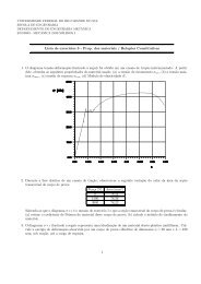
ENG03003 - Mecânica dos Sólidos I - Diretrizes <strong>para</strong> o semestre<br />
2010/1<br />
Jun S. O. Fonseca<br />
29 <strong>de</strong> abril <strong>de</strong> 2010<br />
Resumo<br />
Este texto visa a melhor coor<strong>de</strong>nação entre os <strong>professores</strong> <strong>de</strong> Mecânica dos Sólidos I, uma vez que a partir<br />
<strong>de</strong> agora haverão muitas turmas e muitos <strong>professores</strong>. O objetivo principal é apresentar a fun<strong>da</strong>mentação<br />
losóca <strong>da</strong> disciplina, e como esta se reete em sua organização.<br />
Sumário<br />
1 Organização dos assuntos 2<br />
2 Notação 4<br />
3 Diferenças principais em relação aos livros clássicos 6<br />
3.1 Ênfase em três ou quatro dimensões . . . . . . . . . . . . . . . . . . . . . . . . . . . . . . . . 6<br />
3.2 Ênfase na Elastici<strong>da</strong><strong>de</strong> e Mecânica do Contínuo . . . . . . . . . . . . . . . . . . . . . . . . . . 6<br />
3.3 Convenção <strong>de</strong> sinais . . . . . . . . . . . . . . . . . . . . . . . . . . . . . . . . . . . . . . . . . 7<br />
3.4 Dedução por hipóteses cinemáticas . . . . . . . . . . . . . . . . . . . . . . . . . . . . . . . . . 8<br />
4 Resumo dos tópicos 8<br />
4.1 Deformação . . . . . . . . . . . . . . . . . . . . . . . . . . . . . . . . . . . . . . . . . . . . . . 9<br />
4.1.1 Revisão: . . . . . . . . . . . . . . . . . . . . . . . . . . . . . . . . . . . . . . . . . . . . 9<br />
4.1.2 Deformações: . . . . . . . . . . . . . . . . . . . . . . . . . . . . . . . . . . . . . . . . . 10<br />
4.1.3 Hipótese <strong>de</strong> <strong>de</strong>formações innitesimais . . . . . . . . . . . . . . . . . . . . . . . . . . . 11<br />
4.1.4 Mu<strong>da</strong>nça do sistema <strong>de</strong> coor<strong>de</strong>na<strong>da</strong>s . . . . . . . . . . . . . . . . . . . . . . . . . . . . 13<br />
4.1.5 Deformações Principais: . . . . . . . . . . . . . . . . . . . . . . . . . . . . . . . . . . . 13<br />
4.1.6 Decomposição em parte volumétrica e <strong>de</strong>sviadora . . . . . . . . . . . . . . . . . . . . . 14<br />
4.2 Tensões . . . . . . . . . . . . . . . . . . . . . . . . . . . . . . . . . . . . . . . . . . . . . . . . 14<br />
4.2.1 Revisão <strong>de</strong> forças . . . . . . . . . . . . . . . . . . . . . . . . . . . . . . . . . . . . . . . 14<br />
4.2.2 Equações <strong>de</strong> Equilíbrio . . . . . . . . . . . . . . . . . . . . . . . . . . . . . . . . . . . . 16<br />
4.2.3 Transformação <strong>da</strong>s Tensões . . . . . . . . . . . . . . . . . . . . . . . . . . . . . . . . . 16<br />
4.2.4 Tensões principais . . . . . . . . . . . . . . . . . . . . . . . . . . . . . . . . . . . . . . 17<br />
4.3 Relações constitutivas - Comportamento dos materiais . . . . . . . . . . . . . . . . . . . . . . 17<br />
4.4 Critérios <strong>de</strong> falha . . . . . . . . . . . . . . . . . . . . . . . . . . . . . . . . . . . . . . . . . . . 20<br />
4.4.1 Critérios <strong>de</strong> Escoamento . . . . . . . . . . . . . . . . . . . . . . . . . . . . . . . . . . . 21<br />
4.4.2 Critérios <strong>de</strong> ruptura . . . . . . . . . . . . . . . . . . . . . . . . . . . . . . . . . . . . . 21<br />
4.4.3 Princípio <strong>de</strong> Saint Venant . . . . . . . . . . . . . . . . . . . . . . . . . . . . . . . . . . 21<br />
4.4.4 Princípio <strong>da</strong> superposição <strong>de</strong> efeitos . . . . . . . . . . . . . . . . . . . . . . . . . . . . 22<br />
4.4.5 Energia <strong>de</strong> <strong>de</strong>formação . . . . . . . . . . . . . . . . . . . . . . . . . . . . . . . . . . . . 22<br />
4.5 Problemas isostáticos . . . . . . . . . . . . . . . . . . . . . . . . . . . . . . . . . . . . . . . . . 23<br />
4.5.1 Funções <strong>de</strong> singulari<strong>da</strong><strong>de</strong> . . . . . . . . . . . . . . . . . . . . . . . . . . . . . . . . . . 24<br />
4.6 Tração e compressão . . . . . . . . . . . . . . . . . . . . . . . . . . . . . . . . . . . . . . . . . 26<br />
4.7 Torção . . . . . . . . . . . . . . . . . . . . . . . . . . . . . . . . . . . . . . . . . . . . . . . . . 28<br />
4.7.1 Eixos <strong>de</strong> seção circular . . . . . . . . . . . . . . . . . . . . . . . . . . . . . . . . . . . . 28<br />
4.7.2 Eixos <strong>de</strong> seção não circular . . . . . . . . . . . . . . . . . . . . . . . . . . . . . . . . . 30<br />
4.7.3 Aproximação <strong>para</strong> retângulos estreitos . . . . . . . . . . . . . . . . . . . . . . . . . . . 31<br />
1
4.7.4 Torção <strong>de</strong> seções fecha<strong>da</strong>s <strong>de</strong> pare<strong>de</strong> na . . . . . . . . . . . . . . . . . . . . . . . . . . 32<br />
4.8 Flexão . . . . . . . . . . . . . . . . . . . . . . . . . . . . . . . . . . . . . . . . . . . . . . . . . 33<br />
4.8.1 Cálculo <strong>de</strong> momentos <strong>de</strong> Inércia (revisão) . . . . . . . . . . . . . . . . . . . . . . . . . 34<br />
4.8.2 Energia <strong>de</strong> <strong>de</strong>formação . . . . . . . . . . . . . . . . . . . . . . . . . . . . . . . . . . . . 35<br />
4.8.3 Vigas com forças transversais . . . . . . . . . . . . . . . . . . . . . . . . . . . . . . . . 35<br />
4.8.4 Dimensionamento <strong>de</strong> vigas isostáticas . . . . . . . . . . . . . . . . . . . . . . . . . . . 35<br />
4.9 Cisalhamento em Vigas . . . . . . . . . . . . . . . . . . . . . . . . . . . . . . . . . . . . . . . 36<br />
4.10 Deslocamentos em vigas . . . . . . . . . . . . . . . . . . . . . . . . . . . . . . . . . . . . . . . 37<br />
4.10.1 Teoria <strong>de</strong> vigas <strong>de</strong> Timoshenko . . . . . . . . . . . . . . . . . . . . . . . . . . . . . . . 38<br />
1 Organização dos assuntos<br />
A disciplina é <strong>da</strong><strong>da</strong> segundo a seguinte seqüência:<br />
1. Deformação<br />
(a) Denição <strong>de</strong> <strong>de</strong>formação<br />
(b) Notação <strong>de</strong> <strong>de</strong>formações - Tensor <strong>de</strong>formação innitesimal<br />
(c) Transformação <strong>de</strong> <strong>de</strong>formações<br />
(d) Deformações principais (às vezes apresentado junto com as tensões principais)<br />
(e) Caso particular: elastici<strong>da</strong><strong>de</strong> 2D<br />
(f) Lista 2 <strong>de</strong> exercícios<br />
2. Tensão<br />
(a) Tipos <strong>de</strong> carregamento<br />
(b) Denição <strong>de</strong> tensão<br />
(c) Notação <strong>de</strong> tensões - Tensor tensão<br />
(d) Equações <strong>de</strong> equilíbrio<br />
(e) Transformação <strong>de</strong> tensões<br />
(f) Caso particular: elastici<strong>da</strong><strong>de</strong> 2D<br />
(g) Fatores que afetam a distribuição <strong>de</strong> tensões<br />
(h) Tensões principais<br />
(i) Noção <strong>de</strong> coeciente <strong>de</strong> segurança<br />
(j) Lista 1<br />
3. Relações constitutivas - Comportamento dos materiais<br />
(a) Denições<br />
(b) Diagramas tensão - <strong>de</strong>formação<br />
(c) Diagramas <strong>de</strong> engenharia<br />
(d) Proprie<strong>da</strong><strong>de</strong>s importantes<br />
(e) Lei <strong>de</strong> Hooke generaliza<strong>da</strong><br />
(f) Tipos <strong>de</strong> materias<br />
(g) Princípio <strong>de</strong> Saint Venant<br />
(h) Energia <strong>de</strong> <strong>de</strong>formação<br />
(i) Trabalho externo<br />
(j) Lista 3<br />
2
4. Critérios <strong>de</strong> falha<br />
(a) Teoria <strong>da</strong> máxima tensão cisalhante - Critério <strong>de</strong> Tresca<br />
(b) Teoria <strong>da</strong> máxima energia <strong>de</strong> distorção - Critério <strong>de</strong> Henky-Mises<br />
(c) Teoria <strong>da</strong> máxima tensão normal - Critério <strong>de</strong> Coulomb-Rankine<br />
(d) Teoria <strong>de</strong> Mohr<br />
(e) Outros<br />
(f) Coecientes <strong>de</strong> segurança<br />
(g) Lista 4<br />
5. Isostática <strong>de</strong> Corpos Esbeltos<br />
(a) Procedimento geral <strong>para</strong> solução <strong>de</strong> um problema isostático<br />
(b) Convenções <strong>para</strong> vínculos e carregamentos<br />
(c) Diagramas <strong>de</strong> esforços internos<br />
(d) Equações <strong>de</strong> equilíbrio <strong>para</strong> membros esbeltos<br />
(e) Solução <strong>de</strong> problemas por funções <strong>de</strong> singulari<strong>da</strong><strong>de</strong><br />
(f) Lista 5<br />
6. Tração e Compressão <strong>de</strong> Barras<br />
(a) Equações governantes - <strong>de</strong>dução <strong>da</strong>s equações pela Teoria <strong>da</strong> Elastici<strong>da</strong><strong>de</strong><br />
(b) Energia <strong>de</strong> <strong>de</strong>formação<br />
(c) Dimensionamento <strong>de</strong> barras e cabos<br />
(d) Concentração <strong>de</strong> tensões<br />
(e) Lista s/n<br />
7. Torção<br />
(a) Equações governantes <strong>para</strong> eixo circulares<br />
(b) Energia <strong>de</strong> <strong>de</strong>formação<br />
(c) Dimensionamento <strong>de</strong> eixos submetidos à torção<br />
(d) Ângulo <strong>de</strong> torção (eixos circulares)<br />
(e) Torção <strong>de</strong> eixos não-circulares - Dedução <strong>da</strong>s equações pela Teoria <strong>da</strong> Elastici<strong>da</strong><strong>de</strong><br />
(f) Torção <strong>de</strong> seções fecha<strong>da</strong>s <strong>de</strong> pare<strong>de</strong> na<br />
(g) Concentração <strong>de</strong> tensões<br />
(h) Lista 6<br />
8. Flexão<br />
(a) Teorias mais comuns<br />
(b) Equações governantes - Teoria <strong>de</strong> vigas <strong>de</strong> Euler-Bernoulli<br />
(c) Energia <strong>de</strong> <strong>de</strong>formação<br />
(d) Dimensionamento <strong>de</strong> membros sob exão<br />
(e) Cálculo <strong>de</strong> momentos <strong>de</strong> inércia (revisão)<br />
(f) Vigas <strong>de</strong> vários materiais<br />
(g) Concentração <strong>de</strong> tensões<br />
3
(h) Teoria <strong>de</strong> vigas <strong>de</strong> Timoshenko<br />
(i) Lista 7<br />
9. Deslocamentos em Vigas<br />
(a) Equação <strong>da</strong> linha elástica<br />
(b) Lista 10<br />
10. Cisalhamento <strong>de</strong> Eixos e Vigas<br />
(a) Equações governantes<br />
(b) Distribuição <strong>de</strong> tensões cisalhantes em seções<br />
(c) Energia <strong>de</strong> <strong>de</strong>formação<br />
(d) Dimensionamento <strong>de</strong> membros sob cisalhamento<br />
(e) Centro <strong>de</strong> torção<br />
(f) Concentração <strong>de</strong> tensões<br />
(g) Lista 8<br />
11. Carregamentos Compostos<br />
(a) Princípio <strong>da</strong> superposição <strong>de</strong> efeitos<br />
(b) Lista 9<br />
Observações: Na prática, gasta-se uma semana com uma breve revisão <strong>de</strong> estática (forças, <strong>de</strong>slocamentos).<br />
2 Notação<br />
A disciplina fará uma mu<strong>da</strong>nça <strong>para</strong> uma notação mais próxima à indicial no semestre que vem. Por enquanto,<br />
utilizar-se-á uma notação intermediária. Embora com excessões, reserva-se letras gregas <strong>para</strong> escalares, letras<br />
latinas minúsculas <strong>para</strong> vetores e letras latinas maiúsculas <strong>para</strong> tensores <strong>de</strong> or<strong>de</strong>m superior.<br />
1. vetor posição:<br />
⎧<br />
⎨<br />
p =<br />
⎩<br />
x<br />
y<br />
z<br />
⎫<br />
⎬<br />
⎧<br />
⎨<br />
⎭ , p 0 =<br />
⎩<br />
x 0<br />
y 0<br />
z 0<br />
⎫<br />
⎬<br />
⎭<br />
2. vetor <strong>de</strong>slocamento:<br />
⎧<br />
⎨<br />
d =<br />
⎩<br />
u (x, y, z, t)<br />
v (x, y, z, t)<br />
w (x, y, z, t)<br />
⎫<br />
⎬<br />
⎭<br />
3. matriz ortogonal própria (<strong>de</strong> rotação):<br />
Q : QQ T = I<br />
R : RR T = I<br />
Esta matriz po<strong>de</strong> ser <strong>de</strong>composta em três rotações simples em torno <strong>de</strong> ca<strong>da</strong> eixo, como, por exemplo:<br />
⎤<br />
Q = Q x Q y Q z<br />
⎡<br />
1 0 0<br />
⎡<br />
0 senθ x cosθ x<br />
= ⎣ 0 cosθ x −senθ x<br />
⎦ ⎣<br />
cosθ y 0 senθ y<br />
⎤<br />
0 1 0 ⎦<br />
⎡<br />
⎣<br />
cosθ z −senθ z 0<br />
senθ z cosθ z 0<br />
0 0 1<br />
⎤<br />
⎦<br />
4
4. força <strong>de</strong> superfície (N/m 2 = P a):<br />
t =<br />
⎧<br />
⎨<br />
⎩<br />
t x<br />
t y<br />
t z<br />
⎫<br />
⎬<br />
⎭<br />
5. força <strong>de</strong> corpo (N/m 3 ):<br />
⎧<br />
⎨ b x<br />
b = b y<br />
⎩<br />
b z<br />
⎫<br />
⎬<br />
⎭<br />
6. força resultante(N):<br />
7. Momento <strong>de</strong> forças(Nm):<br />
8. <strong>de</strong>formação innitesimal:<br />
ε =<br />
∇d − (∇d)T<br />
2<br />
¨<br />
m =<br />
⎡<br />
= ⎢<br />
⎣<br />
¨<br />
f =<br />
S<br />
1<br />
2<br />
1<br />
2<br />
S<br />
˚<br />
t dS + b dV<br />
V<br />
˚<br />
p × t dS + p × b dV<br />
V<br />
(<br />
∂u<br />
∂u<br />
∂x<br />
∂y + ∂v<br />
∂x<br />
( ∂u<br />
∂z + ∂w<br />
∂x<br />
ε ij = 1 2<br />
)<br />
)<br />
1<br />
2<br />
1<br />
2<br />
( )<br />
∂u<br />
∂y + ∂v<br />
∂x<br />
(<br />
∂v<br />
∂v<br />
∂y<br />
∂z + ∂w<br />
∂y<br />
( ∂di<br />
+ ∂d )<br />
j<br />
∂p j ∂p i<br />
não se usa letras diferentes <strong>para</strong> as cisalhantes, e se mantém o 1/2.<br />
9. <strong>de</strong>formação nita (<strong>de</strong> Green):<br />
10. <strong>de</strong>formações principais:<br />
E = 1 2<br />
)<br />
(<br />
1 ∂u<br />
2 ∂z + ∂w<br />
(<br />
∂x<br />
1 ∂v<br />
2 ∂z + ∂w<br />
∂y<br />
∂w<br />
∂z<br />
(<br />
)<br />
(∇p) T (∇p) − 1 = 1 (<br />
)<br />
(∇d + I) T (∇d + I) − 1<br />
2<br />
E ij = 1 2<br />
(<br />
∂d i<br />
∂p j<br />
+ ∂d j<br />
∂p i<br />
+<br />
3∑<br />
k=1<br />
)<br />
∂d k ∂d k<br />
∂p j ∂p i<br />
)<br />
)<br />
⎤<br />
⎥<br />
⎦<br />
ελ = Xλ<br />
(ε − λI) X = 0<br />
<strong>de</strong>t (ε − λI) = 0<br />
on<strong>de</strong> X são autovetores (direções principais) e λ são autovalores (direções principais)<br />
⎡<br />
ε 1 0 0<br />
⎤<br />
0 0 ε 3<br />
ε = ⎣ 0 ε 2 0 ⎦ , ε 1 ≥ ε 2 ≥ ε 3<br />
11. normal externa (adimensional):<br />
⎧<br />
⎨ n x<br />
n = n y<br />
⎩<br />
n z<br />
⎫<br />
⎬<br />
⎭<br />
5
⎤<br />
12. Tensão <strong>de</strong> Cauchy:<br />
t = σn<br />
on<strong>de</strong><br />
⎡<br />
σ xx σ xy σ xz<br />
σ zx σ zy σ zz<br />
σ = ⎣ σ yx σ yy σ yz<br />
⎦ .<br />
Não se usa letras diferentes <strong>para</strong> as cisalhantes. No entanto, usa-se a letra τ <strong>para</strong> uma tensão cisalhante<br />
genérica, em algumas ocasiões.<br />
13. Equações <strong>de</strong> equilíbrio:<br />
ou<br />
∂σ xx<br />
∂x<br />
∂σ xy<br />
∂x<br />
∂σ xz<br />
∂x<br />
+ ∂σ yx<br />
∂y<br />
+ ∂σ yy<br />
∂y<br />
+ ∂σ yz<br />
∂y<br />
∇ · σ + b = 0<br />
+ ∂σ zx<br />
∂z + b x = 0<br />
+ ∂σ zy<br />
∂z + b y = 0<br />
+ ∂σ zz<br />
∂z + b z = 0<br />
14. Constantes elásticas: Módulo <strong>de</strong> Young (ou módulo <strong>de</strong> elastici<strong>da</strong><strong>de</strong> longitudinal) E, coeciente <strong>de</strong> Poisson<br />
ν, constantes <strong>de</strong> Lamé λ e µ, módulo <strong>de</strong> elastici<strong>da</strong><strong>de</strong> transversal G ou µ, e módulo volumétrico κ.<br />
15. Funções <strong>de</strong> singulari<strong>da</strong><strong>de</strong>: A maior parte dos livros usam a notação <strong>de</strong> Macaulay <strong>de</strong> 1919 〈x − a〉 n . Nesta<br />
disciplina, faz-se a conexão com a notação utiliza<strong>da</strong> nas disciplinas <strong>de</strong> matemática, isto é, a função <strong>de</strong><br />
Heavisi<strong>de</strong> (<strong>de</strong>grau unitário) H (x − a) e Dirac (impulso unitário) δ (x − a). As <strong>de</strong>riva<strong>da</strong>s são representa<strong>da</strong>s<br />
pelas notações convencionais d ou ′ dx<br />
.<br />
3 Diferenças principais em relação aos livros clássicos<br />
Algumas diferenças fun<strong>da</strong>mentais são implementa<strong>da</strong>s nesta disciplina em relação ao conteúdo <strong>da</strong> maioria dos<br />
livros textos existentes. Elas se reetem a gradual migração <strong>da</strong> disciplina <strong>para</strong> se basear na Mecânica do Contínuo<br />
e aten<strong>de</strong>r melhor a Engenharia Mecânica, on<strong>de</strong> geometrias simples facilmente i<strong>de</strong>nticáveis como vigas ou barras<br />
ocorrem com pouca freqüência. O engenheiro mecânico <strong>de</strong>ve ser pre<strong>para</strong>do <strong>para</strong> ser capaz <strong>de</strong> operar programas<br />
computacionais <strong>de</strong> análise estrutural, utilizando teorias estruturais e a elastici<strong>da</strong><strong>de</strong>.<br />
3.1 Ênfase em três ou quatro dimensões<br />
Na Engenharia Mecânica, a maioria dos problemas é tridimensional, completamente dinâmico ou ao menos<br />
com vibrações. Desta maneira, é imperativo enfatizar a abor<strong>da</strong>gem dinâmica e tridimensional <strong>da</strong> Mecânica dos<br />
Sólidos. Casos bidimensionais estáticos são excelentes exemplos, mas <strong>de</strong>vem ser apresentados com ressalvas.<br />
Métodos exclusivamente bidimensionais <strong>de</strong>vem ser apresentados com muitas ressalvas (especialmente o círculo<br />
<strong>de</strong> Mohr e fórmulas prontas <strong>de</strong> rotação).<br />
Apesar <strong>de</strong> não constarem no programa atual, exemplos dinâmicos simples <strong>de</strong>vem ser apresentados em barras<br />
e vigas. Sempre que possível, ressaltar que to<strong>da</strong>s a variáveis (forças, <strong>de</strong>slocamentos, <strong>de</strong>formações e tensões) são<br />
funções <strong>da</strong> posição (as três coor<strong>de</strong>na<strong>da</strong>s materiais) e do tempo.<br />
3.2 Ênfase na Elastici<strong>da</strong><strong>de</strong> e Mecânica do Contínuo<br />
As <strong>de</strong>duções <strong>da</strong>s equações <strong>de</strong> barra, viga e torção <strong>de</strong>vem ser apresenta<strong>da</strong>s através <strong>da</strong> aplicação <strong>da</strong>s hipóteses<br />
cinemáticas e dinâmicas nas equações <strong>da</strong> Elastici<strong>da</strong><strong>de</strong>.<br />
O conceito <strong>de</strong> tensão <strong>de</strong>ve ser apresentado não somente através <strong>de</strong> um cubo innitesimal, como também a<br />
partir <strong>da</strong> fórmula <strong>de</strong> Cauchy.<br />
As equações <strong>de</strong> equilíbrio e movimento <strong>de</strong>vem ser <strong>de</strong>duzi<strong>da</strong>s também através do equilíbrio integral <strong>de</strong> um<br />
corpo. A relação entre a mecânica dos sólidos com a mecânica dos uidos <strong>de</strong>ve ser lembra<strong>da</strong>.<br />
6
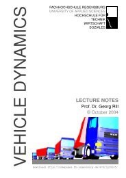
3.3 Convenção <strong>de</strong> sinais<br />
Figura 1: Convenção <strong>de</strong> sinais<br />
A Engenharia Mecânica normalmente coloca os eixos com o z <strong>para</strong> cima. Não há uma convenção única <strong>para</strong> os<br />
sinais <strong>de</strong> momentos e forças cortantes. Desta maneira, <strong>de</strong>ve-se apresentar uma convenção <strong>de</strong> sinais mas enfatizar<br />
que outras são possíveis.<br />
A convenção <strong>de</strong> sinais mais coerente vem <strong>da</strong> <strong>de</strong>nição <strong>de</strong> tensão. Toma-se um corpo e corta-se com um plano<br />
(gura1). Da<strong>da</strong> a fórmula <strong>de</strong> Cauchy<br />
t = σn ,<br />
on<strong>de</strong> t é a força interna <strong>de</strong> superfície, σ é a tensão <strong>de</strong> Cauchy e n a normal externa <strong>da</strong> superfície, a resultante<br />
<strong>da</strong> força interna t na superfície do corte é <strong>da</strong><strong>da</strong> por<br />
¨<br />
f = t dS<br />
que po<strong>de</strong> ser <strong>de</strong>composta em uma componente normal (força normal) e duas tangenciais (forças cortantes). O<br />
momento <strong>da</strong> força na superfície em relação ao seu centrói<strong>de</strong> é <strong>da</strong>do por<br />
¨<br />
m = p × t dS<br />
S<br />
que po<strong>de</strong> ser <strong>de</strong>composto em uma componente normal (momento torçor) e duas componentes tangenciais (momentos<br />
etores).<br />
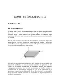
Na situação mais comum (gura2), a tensão é <strong>da</strong><strong>da</strong> por<br />
S<br />
que coinci<strong>de</strong> com o esforço interno<br />
Integrando na seção, isto resulta em<br />
σ xx = −Ey d2 v<br />
dx 2<br />
t x = σ xx = −Ey d2 v<br />
dx 2 .<br />
¨<br />
f x =<br />
S<br />
t x dydz = 0<br />
7
Figura 2: viga comum<br />
pelo fato do eixo ser centroi<strong>da</strong>l. O momento resultante po<strong>de</strong> ser calculado como<br />
⎧ ⎫ ⎫<br />
¨ ⎨ ⎬ ⎬<br />
ou ain<strong>da</strong><br />
⎧<br />
⎨<br />
⎩<br />
⎧<br />
⎨<br />
⎩<br />
m =<br />
S<br />
m x<br />
m y<br />
m z<br />
⎫<br />
⎬<br />
⎭ = ¨S<br />
m x<br />
m y<br />
m z<br />
⎫<br />
⎬<br />
⎭ = ¨S<br />
⎩<br />
⎧<br />
⎨<br />
⎩<br />
⎧<br />
⎨<br />
⎩<br />
0<br />
y<br />
z<br />
m z = EI zz<br />
d 2 v<br />
dx 2<br />
⎧<br />
⎨ t x<br />
⎭ × 0<br />
⎩ ⎭ dydz<br />
0<br />
⎫<br />
⎬<br />
⎭ dydz<br />
0<br />
z t x<br />
−y t x<br />
0<br />
0<br />
y 2 E d2 v<br />
dx 2<br />
σ xx = −y m z<br />
I zz<br />
,<br />
m z = −P (L − x0)<br />
⎫<br />
⎬<br />
⎭ dydz<br />
on<strong>de</strong> o sinal que aparece na <strong>de</strong>dução consistente não é o usualmente encontrado em livros.<br />
Deixando-se esta explicação pernóstica <strong>de</strong> lado, na prática isto signica que uma convenção consistente <strong>de</strong><br />
sinais toma a resultante <strong>de</strong> forças e momentos aplicados pelo lado direito <strong>da</strong> peça sobre a seção. No entanto, esta<br />
não é a convenção mais usa<strong>da</strong> pelos livros. Normalmente se utiliza a convenção contrária, isto é, a resultante<br />
pelo lado esquerdo.<br />
Resultado: não há como não confundir os alunos, pois livros diferentes trazem convenções diferentes! Só é<br />
importante explicar a diversi<strong>da</strong><strong>de</strong> <strong>de</strong> convenções.<br />
3.4 Dedução por hipóteses cinemáticas<br />
A maior parte <strong>da</strong>s <strong>de</strong>duções <strong>de</strong>ve ser feita a partir <strong>de</strong> hipóteses cinemáticas. A maior parte dos livros preferem<br />
as hipóteses sobre as forças. Isto será melhor explicitado no <strong>de</strong>correr <strong>de</strong>ste texto.<br />
ste text.<br />
4 Resumo dos tópicos<br />
Apresenta-se agora um resumo dos tópicos <strong>para</strong> ns <strong>de</strong> harmonizar a notação e as convenções <strong>de</strong> sinais entre os<br />
<strong>professores</strong>. Destacam-se os temas não encontrados normalmente nos livros texto.<br />
8
4.1 Deformação<br />
4.1.1 Revisão:<br />
A apresentação <strong>de</strong>ste tópico é precedi<strong>da</strong> <strong>de</strong> uma revisão <strong>de</strong> cinemática.<br />
Posição: o vetor posição localiza um ponto material em relação a uma referência. Em uma <strong>de</strong>scrição <strong>de</strong> um<br />
movimento, este vetor é uma função do tempo.<br />
⎧<br />
⎨<br />
p =<br />
⎩<br />
x (t)<br />
y (t)<br />
z (t)<br />
⎫<br />
⎬<br />
⎧<br />
⎨<br />
⎭ , p 0 =<br />
⎩<br />
Normalmente se simplica a notação <strong>de</strong> p (t = 0) por p 0 .<br />
Deslocamento: a variação <strong>da</strong> posição. É uma função <strong>da</strong> posição e do tempo.<br />
x 0<br />
y 0<br />
z 0<br />
⎫<br />
⎬<br />
⎭<br />
⎧<br />
⎨<br />
⎩<br />
d (x, y, z, t) = p − p 0<br />
⎫<br />
⎬<br />
u (x, y, z, t)<br />
v (x, y, z, t)<br />
w (x, y, z, t)<br />
⎭ = ⎧<br />
⎨<br />
⎩<br />
x − x 0<br />
y − y 0<br />
z − z 0<br />
⎫<br />
⎬<br />
⎭<br />
Destacar que a representação do <strong>de</strong>slocamento (e qualquer outra variável <strong>da</strong> mecânica) como uma função<br />
contínua do espaço e do tempo implica na Mecânica do Contínuo. O corpo é consi<strong>de</strong>rado um meio contínuo no<br />
espaço e tempo, on<strong>de</strong> há material em qualquer coor<strong>de</strong>na<strong>da</strong>. As proprie<strong>da</strong><strong>de</strong>s materiais variam continuamente.<br />
Apesar <strong>de</strong>sta hipótese ser obviamente fura<strong>da</strong>, a possibili<strong>da</strong><strong>de</strong> <strong>de</strong> tomar limites (e utilizar o po<strong>de</strong>r do Cálculo) a<br />
justicam.<br />
Apresenta-se aqui vários exemplos <strong>de</strong> <strong>de</strong>slocamentos (incluir <strong>de</strong>senhos <strong>de</strong> cubinhos unitários se movendo):<br />
⎧<br />
⎨<br />
ˆ translação unidimensional: d =<br />
⎩<br />
⎧<br />
⎨<br />
ˆ translação geral: d =<br />
⎩<br />
u (t)<br />
v (t)<br />
w (t)<br />
⎧<br />
⎨<br />
ˆ dilatação uniforme: d =<br />
⎩<br />
⎫<br />
⎬<br />
⎭<br />
α (t) x<br />
α (t) y<br />
α (t) z<br />
u (t)<br />
0<br />
0<br />
⎫<br />
⎬<br />
⎭<br />
⎫<br />
⎬<br />
⎧<br />
⎨<br />
ˆ extensão (ou contração) pura em x: d =<br />
⎩<br />
⎧<br />
⎨<br />
ˆ distorção pura no plano xy: d =<br />
⎩<br />
⎭<br />
γ (t) y<br />
0<br />
0<br />
α (t) x<br />
0<br />
0<br />
⎫<br />
⎬<br />
⎭<br />
Introduz-se neste ponto a simplicação <strong>da</strong> Estática. A <strong>de</strong>pendência do tempo é ignora<strong>da</strong> e o sistema é <strong>de</strong>scrito<br />
apenas pela posição inicial e nal. Explicar as implicações: <strong>de</strong>srespeita o princípio <strong>da</strong> conservação <strong>de</strong> energia,<br />
e torna difícil qualquer análise dinâmica. Simplica bastante as equações. Serve <strong>para</strong> fenômenos que ocorrem<br />
muito lentamente ou <strong>para</strong> sistemas após o amortecimento ter dissipado to<strong>da</strong> energia cinética. Po<strong>de</strong> servir <strong>para</strong><br />
sistemas dinâmicos através do uso <strong>de</strong> coecientes <strong>de</strong> segurança.<br />
Apresentam-se outros exemplos <strong>de</strong> <strong>de</strong>slocamento, já <strong>de</strong>ntro <strong>da</strong> estática:<br />
⎧<br />
⎨<br />
ˆ extensão simples em x: d =<br />
⎩<br />
αx<br />
βy<br />
βz<br />
⎫<br />
⎬<br />
⎭<br />
⎫<br />
⎬<br />
⎭<br />
9
⎧<br />
⎨<br />
ˆ distorção pura no plano xy: d =<br />
⎩<br />
⎧<br />
⎨<br />
ˆ rotação pura em torno <strong>de</strong> z: d =<br />
⎩<br />
4.1.2 Deformações:<br />
0<br />
γx<br />
0<br />
Figura 3: <strong>de</strong>formação<br />
⎫<br />
⎬<br />
⎭<br />
x cosθ z − y senθ z − x 0<br />
x senθ z + y cosθ z − y 0<br />
0<br />
⎫<br />
⎬<br />
⎭ = Qp 0 − p 0<br />
Deformação é apresenta<strong>da</strong> como uma medi<strong>da</strong> matemática <strong>da</strong> mu<strong>da</strong>nça <strong>de</strong> forma <strong>de</strong> um elemento <strong>de</strong> volume.<br />
Esta mu<strong>da</strong>nça <strong>de</strong> forma po<strong>de</strong> ser representa<strong>da</strong> como uma mu<strong>da</strong>nça <strong>de</strong> comprimento <strong>de</strong> um elemento qualquer<br />
<strong>de</strong> linha (gura 3). Do Cálculo, um elemento <strong>de</strong> linha é <strong>da</strong>do por ds e na conguração inicial por ds 0 . Mas<br />
a posição nalp é uma função <strong>da</strong> posição inicial p 0 , e a transformação <strong>da</strong> posição nal <strong>para</strong> a inicial po<strong>de</strong> ser<br />
interpreta<strong>da</strong> matematicamente como um mapeamento, expresso através <strong>de</strong> seus gradientes (a matriz jacobiana).<br />
No caso, o gradiente <strong>de</strong> um vetor é um tensor, o gradiente <strong>de</strong> <strong>de</strong>formações, representado por F.<br />
F ij = ∂p i<br />
F =<br />
e o elemento <strong>de</strong> linha na posição nal é <strong>da</strong>do por<br />
⎧<br />
⎨<br />
ds =<br />
⎩<br />
∂p 0j<br />
⎡<br />
⎢<br />
⎣<br />
dx<br />
dy<br />
dz<br />
∂x<br />
∂x 0<br />
∂y<br />
∂x 0<br />
∂z<br />
∂x 0<br />
O quadrado do comprimento (euclidiano) é <strong>da</strong>do por<br />
⎫<br />
⎬<br />
∂x<br />
∂y 0<br />
∂y<br />
∂y 0<br />
∂z<br />
∂y 0<br />
∂x<br />
∂z 0<br />
∂y<br />
∂z 0<br />
∂z<br />
∂z 0<br />
⎭ = Fds 0 .<br />
‖ds‖ 2 2<br />
= (ds) T (ds)<br />
= (ds 0 ) F T F (ds 0 )<br />
e a meta<strong>de</strong> <strong>da</strong> diferença entre os comprimentos nal e inicial é <strong>da</strong>do por<br />
1<br />
(<br />
)<br />
‖ds‖ 2 2<br />
2<br />
− ‖ds 0‖ 2 2<br />
= (ds 0 ) 1 (<br />
F T F − I ) (ds 0 )<br />
2<br />
10<br />
⎤<br />
⎥<br />
⎦
on<strong>de</strong> <strong>de</strong>ne-se o tensor <strong>de</strong> <strong>de</strong>formações <strong>de</strong> Green(-Lagrange) como uma relação entre as diferenças dos comprimentos<br />
<strong>de</strong> linha por<br />
E = 1 (<br />
F T F − I ) .<br />
2<br />
Em termos <strong>de</strong> componentes, o tensor <strong>de</strong> <strong>de</strong>formações <strong>de</strong> Green se escreve como:<br />
( 3∑<br />
)<br />
E ij = 1 ∂p k ∂p k<br />
− δ ij<br />
2 ∂p 0i ∂p 0j<br />
k=1<br />
on<strong>de</strong> o <strong>de</strong>lta <strong>de</strong> Kronecker é <strong>de</strong>nido como a i<strong>de</strong>nti<strong>da</strong><strong>de</strong> por<br />
{<br />
0 se i ≠ j<br />
δ ij =<br />
1 se i = j<br />
.<br />
Substuindo p = d + p 0 na relação anterior e usando a proprie<strong>da</strong><strong>de</strong> <strong>de</strong> que ∇p 0 = I, resulta em<br />
E = 1 (<br />
)<br />
∇d + (∇d) T + (∇d) T ∇d<br />
2<br />
(<br />
)<br />
E ij = 1 ∂d i<br />
+ ∂d 3∑<br />
j ∂d k ∂d k<br />
+<br />
2 ∂p 0j ∂p 0i ∂p 0i ∂p 0i<br />
ou componente por componente<br />
(<br />
E 11 = 1 2 ∂u ( ) 2 ( ) 2 ( ) ) 2 ∂u ∂v ∂w<br />
2 ∂x + + +<br />
∂x ∂x ∂x<br />
(<br />
E 22 = 1 2 ∂v ( ) 2 ( ) 2 ( ) ) 2 ∂u ∂v ∂w<br />
2 ∂y + + +<br />
∂y ∂y ∂y<br />
(<br />
E 33 = 1 2 ∂w ( ) 2 ( ) 2 ( ) ) 2 ∂u ∂v ∂w<br />
2 ∂z + + +<br />
∂z ∂z ∂z<br />
E 12 = 1 ( ∂u<br />
2 ∂y + ∂v<br />
∂x + ∂u ∂u<br />
∂x ∂y + ∂v ∂v<br />
∂x ∂y + ∂w )<br />
∂w<br />
∂x ∂y<br />
E 13 = 1 ( ∂u<br />
2 ∂z + ∂w<br />
∂x + ∂u ∂u<br />
∂x ∂z + ∂v ∂v<br />
∂x ∂z + ∂w )<br />
∂w<br />
∂x ∂z<br />
E 23 = 1 ( ∂w<br />
2 ∂y + ∂v<br />
∂z + ∂u ∂u<br />
∂z ∂y + ∂v ∂v<br />
∂z ∂y + ∂w )<br />
∂w<br />
∂z ∂y<br />
Um problema que aparece neste tópico é que os conceitos <strong>de</strong> cálculo vetorial estão sendo vistos simultaneamente<br />
com a disciplina <strong>de</strong> Matemática Aplica<strong>da</strong>. Normalmente o professor tem que apresentar os operadores <strong>de</strong><br />
gradiente e divergente.<br />
4.1.3 Hipótese <strong>de</strong> <strong>de</strong>formações innitesimais<br />
Neste caso, consi<strong>de</strong>ra-se que as <strong>de</strong>riva<strong>da</strong>s dos <strong>de</strong>slocamentos sejam bastante pequenas, ou pelo menos sucientemente<br />
pequenas <strong>para</strong> <strong>de</strong>sconsi<strong>de</strong>rar os produtos <strong>de</strong> <strong>de</strong>riva<strong>da</strong>s. Desta forma o tensor <strong>de</strong> <strong>de</strong>formações <strong>de</strong> Green<br />
se simplica <strong>para</strong> o tensor <strong>de</strong> <strong>de</strong>formações innitesimais ε:<br />
ε = 1 2<br />
ε ij = 1 2<br />
k=1<br />
(∇d + (∇d) T )<br />
( ∂di<br />
+ ∂d )<br />
j<br />
∂p j ∂p i<br />
11
ou em componentes<br />
ε 11 = ∂u<br />
∂x<br />
ε 22 = ∂v<br />
∂y<br />
ε 33 = ∂w<br />
∂z<br />
ε 12 = 1 ( ∂u<br />
2 ∂y + ∂v )<br />
∂x<br />
ε 13 = 1 ( ∂u<br />
2 ∂z + ∂w )<br />
∂x<br />
ε 23 = 1 ( ∂w<br />
2 ∂y + ∂v )<br />
∂z<br />
O tensor innitesimal po<strong>de</strong> ser uma aproximação muito boa na maior parte <strong>da</strong>s situações <strong>de</strong> engenharia<br />
mecânica, mas sempre <strong>de</strong>ve-ser ressaltar que vale apenas <strong>para</strong> pequenas <strong>de</strong>formações. Um exemplo claro <strong>da</strong>s<br />
limitações aparece na rotação pura, por exemplo em torno <strong>de</strong> z.<br />
na qual po<strong>de</strong>-se <strong>de</strong>senvolver como:<br />
⎧<br />
⎨<br />
d =<br />
⎩<br />
x cosθ z − y senθ z − x 0<br />
x senθ z + y cosθ z − y 0<br />
0<br />
d = Qp 0 − p 0 ⇒<br />
∇d = Q − I<br />
o tensor <strong>de</strong> Green ca (corretamente)<br />
E = 1 (<br />
)<br />
Q − I + (Q − I) T + (Q − I) T (Q − I)<br />
2<br />
= 1 (<br />
Q − I + Q T − I + Q T Q − Q T − Q + I )<br />
2<br />
= 0<br />
e o innitesimal ca<br />
⎫<br />
⎬<br />
ε = 1 (∇d )<br />
+ (∇d) T<br />
2<br />
= 1 (<br />
Q − I + Q T − I )<br />
⎡<br />
2<br />
cosθ z − 1 0 0<br />
⎤<br />
ε = ⎣ 0 cosθ z − 1 0 ⎦<br />
0 0 cosθ z − 1<br />
ou seja, aponta erroneamente uma contração nos três eixos. A or<strong>de</strong>m <strong>de</strong> gran<strong>de</strong>za do erro po<strong>de</strong> facilmente chegar<br />
próxima às <strong>de</strong>formações usuais em engenharia, por exemplo se o ângulo θ z for próximo a 1 ◦ , que resulta em<br />
cos 1 ◦ − 1 = 1, 52 × 10 −4 . Ou seja, em um movimento <strong>de</strong> corpo rígido sem <strong>de</strong>formação, o tensor innitesimal<br />
erroneamente aponta uma <strong>de</strong>formação compressiva enorme.<br />
A partir <strong>da</strong>qui, usa-se somente o tensor innitesimal, embora sempre que possível <strong>de</strong>ve se ressaltar a possibili<strong>da</strong><strong>de</strong><br />
<strong>de</strong> erros.<br />
Informar que a conguração inicial e nal se confun<strong>de</strong>m, e não haverá mais uma diferenciação entre elas.<br />
Interpretação geométrica do tensor innitesimal:<br />
Inserir aqui o que se encontra em qualquer livro. Diferenciar as componentes normais (extensões) <strong>da</strong>s<br />
componentes tangenciais (distorções).<br />
Apresentar os exemplos <strong>de</strong> <strong>de</strong>slocamento anteriores:<br />
12<br />
⎭
⎧<br />
⎨<br />
ˆ translação unidimensional: d =<br />
⎩<br />
⎧<br />
⎨<br />
ˆ translação geral: d =<br />
⎩<br />
u (t)<br />
v (t)<br />
w (t)<br />
⎧<br />
⎨<br />
ˆ dilatação uniforme: d =<br />
⎩<br />
u (t)<br />
0<br />
0<br />
⎫ ⎡<br />
⎬<br />
⎭ ⇒ ε = ⎣<br />
α (t) x<br />
α (t) y<br />
α (t) z<br />
⎧<br />
⎨<br />
ˆ extensão (ou contração) pura em x: d =<br />
⎩<br />
⎧<br />
⎨<br />
ˆ distorção pura no plano xy: d =<br />
⎩<br />
⎧<br />
⎨<br />
ˆ extensão simples em x: d =<br />
⎩<br />
αx<br />
βy<br />
βz<br />
⎧<br />
⎨<br />
ˆ distorção pura no plano xy: d =<br />
⎩<br />
⎫ ⎡<br />
⎬<br />
⎭ ⇒ ε = ⎣<br />
0 0 0<br />
0 0 0<br />
0 0 0<br />
0 0 0<br />
0 0 0<br />
0 0 0<br />
⎫ ⎡<br />
⎬<br />
⎭ ⇒ ε = ⎣ α (t) 0 0<br />
0 α (t) 0<br />
0 0 α (t)<br />
γ (t) y<br />
0<br />
0<br />
α (t) x<br />
0<br />
0<br />
⎤<br />
⎦<br />
⎫ ⎡<br />
⎬<br />
⎭ ⇒ ε = ⎣<br />
⎤<br />
⎦<br />
⎫ ⎡<br />
⎬<br />
⎭ ⇒ ε = ⎣<br />
⎫ ⎡<br />
⎬<br />
⎭ ⇒ ε = ⎣ α 0 0<br />
0 β 0<br />
0 0 β<br />
0<br />
γx<br />
0<br />
4.1.4 Mu<strong>da</strong>nça do sistema <strong>de</strong> coor<strong>de</strong>na<strong>da</strong>s<br />
⎫ ⎡<br />
⎬<br />
⎭ ⇒ ε = ⎣<br />
1<br />
0<br />
1<br />
⎤<br />
⎦<br />
α (t) 0 0<br />
0 0 0<br />
0 0 0<br />
⎤<br />
2 γ (t) 0<br />
⎦<br />
2 γ (t) 0 0<br />
0 0 0<br />
⎤<br />
⎦<br />
1<br />
0<br />
1<br />
2 γ 0<br />
2 γ 0 0<br />
0 0 0<br />
Apresenta-se aqui as mu<strong>da</strong>nças <strong>de</strong> coor<strong>de</strong>na<strong>da</strong>s: Mostrar que a mu<strong>da</strong>nça <strong>de</strong> origem não faz a menor diferença<br />
no <strong>de</strong>slocamento e <strong>de</strong>formações, mas que a rotação do sistema faz. Esta rotação se representa como (<strong>de</strong>duzir em<br />
aula):<br />
ˆ posição e <strong>de</strong>slocamentos: p ′ = Q T p<br />
ˆ <strong>de</strong>formação: ε ′ = QεQ T<br />
4.1.5 Deformações Principais:<br />
⎧<br />
⎨<br />
⎩<br />
i ′<br />
j'<br />
k ′<br />
⎫<br />
⎬<br />
⎭ = Q ⎧<br />
⎨<br />
⎩<br />
d ′ = Q T d<br />
O tensor <strong>de</strong>formação representa uma transformação <strong>de</strong> um elemento <strong>de</strong> linha. Se este tensor for diagonal, isto<br />
signica que o elemento <strong>de</strong> linha se exten<strong>de</strong> ou se contrai sem mu<strong>da</strong>r <strong>de</strong> direção. Pela matemática, sempre<br />
existem ao menos três direções na qual o elemento <strong>de</strong> linha somente se exten<strong>de</strong>. Isto é escrito como<br />
εX = λX<br />
on<strong>de</strong> X é um elemento <strong>de</strong> linha, que após se <strong>de</strong>formar (εX), continua na mesma direção, isto é, é um múltiplo<br />
<strong>de</strong> si mesmo (λX).<br />
Matemáticamente, isto é um problema <strong>de</strong> autovalores λ e autovetores X do tensor <strong>de</strong> <strong>de</strong>formações, que se<br />
<strong>de</strong>senvolve como:<br />
i<br />
j<br />
k<br />
⎫<br />
⎬<br />
⎭<br />
εX = λX<br />
εX − λIX = 0<br />
(ε − λI) X = 0<br />
⇒<br />
<strong>de</strong>t (ε − λI) = 0<br />
13<br />
⎤<br />
⎦<br />
⎤<br />
⎦
<strong>de</strong> on<strong>de</strong> se calculam os valores <strong>de</strong> λ <strong>para</strong> que ε − λI seja singular. Para isto se resolve as raízes do polinômio<br />
que resulta do <strong>de</strong>terminante. Estas raízes são sempre reais (pois a <strong>de</strong>formação é simétrica), mas po<strong>de</strong>m ser<br />
repeti<strong>da</strong>s. Explicar o que representam as raízes repeti<strong>da</strong>s.<br />
Depois <strong>de</strong> alguns exemplos, apresenta-se o círculo <strong>de</strong> Mohr como um dispositivo <strong>para</strong> casos bidimensionais.<br />
4.1.6 Decomposição em parte volumétrica e <strong>de</strong>sviadora<br />
Qualquer tensor <strong>de</strong> segun<strong>da</strong> or<strong>de</strong>m po<strong>de</strong> ser <strong>de</strong>composto <strong>de</strong> várias maneiras. As mais úteis são a <strong>de</strong>composição<br />
polar e a <strong>de</strong>composição em parte esférica e <strong>de</strong>sviadora. Esta última visa a se<strong>para</strong>r os efeitos <strong>de</strong> mu<strong>da</strong>nça pura<br />
<strong>de</strong> volume e a mu<strong>da</strong>nça <strong>de</strong> forma:<br />
ε = ε s + ε d<br />
on<strong>de</strong><br />
ou por extenso:<br />
ε s =<br />
ε d =<br />
⎡<br />
⎣<br />
⎡<br />
⎣<br />
ε xx+ε yy+ε zz<br />
ε s = 1 tr (ε) I<br />
3<br />
ε d = ε − ε s<br />
3<br />
0 0<br />
ε<br />
0<br />
xx+ε yy+ε zz<br />
3<br />
0<br />
0 0<br />
2ε xx−ε yy−ε zz<br />
ε xx+ε yy+ε zz<br />
3<br />
3<br />
ε xy ε xz<br />
ε xy<br />
−ε xx+2ε yy−ε zz<br />
3<br />
ε yz<br />
ε xz ε yz<br />
−ε xx−ε yy+2ε zz<br />
3<br />
⎤<br />
⎦<br />
⎤<br />
⎦ .<br />
Como exemplos, a dilatação pura só tem a parte volumétrica, a distorção pura só tem a parte <strong>de</strong>sviadora e a<br />
extensão simples ca:<br />
⎡ ⎤<br />
α 0 0<br />
ε = ⎣ 0 β 0 ⎦ ⇒<br />
0 0 β<br />
⎡ ⎤<br />
ε s = α + 2β 1 0 0<br />
⎣ 0 1 0 ⎦<br />
3<br />
0 0 1<br />
⎡<br />
2α−2β<br />
⎤<br />
3<br />
0 0<br />
ε d = ⎣<br />
−α+β<br />
0<br />
⎦<br />
0 0<br />
<strong>de</strong> on<strong>de</strong> se conclui que se β = − 1 2α, a parte volumétrica é nula.<br />
4.2 Tensões<br />
3<br />
0<br />
Este é um dos temas mais difíceis <strong>da</strong> engenharia. Segundo o prof. Luiz T. V. Pereira, <strong>da</strong> UFSC, a maioria dos<br />
engenheiros formados não conseguem <strong>de</strong>nir o que é tensão.<br />
4.2.1 Revisão <strong>de</strong> forças<br />
Segundo os livros <strong>de</strong> Física, força é a ação <strong>de</strong> um corpo sobre outro. Sua existência é comprova<strong>da</strong> apenas por<br />
seus efeitos, como aceleração ou <strong>de</strong>formação.<br />
Na mecânica dos sólidos, as forças são sempre distribuí<strong>da</strong>s. As forças concentra<strong>da</strong>s só existem como aproximações,<br />
seja como resultantes ou no contexto do princípio <strong>de</strong> Saint Venant.<br />
−α+β<br />
3<br />
14
As forças po<strong>de</strong>m ser distribuí<strong>da</strong>s em um todos os pontos <strong>de</strong> uma região <strong>de</strong> um corpo. Neste caso são chama<strong>da</strong>s<br />
<strong>de</strong> forças <strong>de</strong> corpo, e <strong>de</strong>ni<strong>da</strong>s como força por uni<strong>da</strong><strong>de</strong> <strong>de</strong> volume.<br />
⎧<br />
⎫<br />
⎨ b x (x, y, z, t) ⎬ (<br />
b = b y (x, y, z, t) N/m<br />
3 ) .<br />
⎩<br />
⎭<br />
b z (x, y, z, t)<br />
Normalmente a força <strong>de</strong> corpo é externa (isto é, aplica<strong>da</strong> por outro corpo). Os tipos mais comuns <strong>de</strong> forças <strong>de</strong><br />
corpo são a gravi<strong>da</strong><strong>de</strong> e o magnetismo. A gravi<strong>da</strong><strong>de</strong> é normalmente consi<strong>de</strong>ra<strong>da</strong> constante em valor e direção<br />
<strong>para</strong> corpos pequenos próximos a superfície terrestre. A resultante <strong>de</strong> uma força <strong>de</strong> corpo é <strong>da</strong><strong>da</strong> por<br />
˚<br />
f = b dV .<br />
As forças distribuí<strong>da</strong>s mais importantes são as <strong>de</strong> superfície. Elas são aplica<strong>da</strong>s em uma superfície do corpo.<br />
As forças externas mais comuns <strong>de</strong> superfície são as <strong>de</strong> contato mecânico e as <strong>de</strong> campo elétrico.<br />
⎧<br />
⎫<br />
⎨ t x (x, y, z, t) ⎬ (<br />
t = t y (x, y, z, t) N/m<br />
2 ) .<br />
⎩<br />
⎭<br />
t z (x, y, z, t)<br />
A resultante <strong>de</strong> uma força <strong>de</strong> superfície é <strong>da</strong><strong>da</strong> por<br />
¨<br />
f =<br />
t dS .<br />
Um aspecto importante <strong>da</strong>s forças <strong>de</strong> superfície é a <strong>de</strong>nição <strong>de</strong> força interna. Se um corpo for partido<br />
por uma superfície, é <strong>de</strong> se esperar que haja uma distribuição <strong>de</strong> forças sobre esta superfície, representando<br />
as forças que estão sendo transmiti<strong>da</strong>s <strong>de</strong> uma parte do corpo à outra. A esta distribuição <strong>da</strong>mos o nome <strong>de</strong><br />
forças internas, e são sempre <strong>de</strong> superfície pois a fronteira entre duas partes <strong>de</strong> um corpo é uma superfície. As<br />
resultantes <strong>de</strong> forças e momentos internos recebem nomes como força normal, força cortante, momento etor e<br />
momento torçor.<br />
Em um ponto do corpo, a força interna varia conforme a orientação do plano <strong>de</strong> corte. Dá-se o nome <strong>de</strong><br />
tensão ao ente matemático que relaciona a força interna em um ponto com a orientação do plano <strong>de</strong> corte. Esta<br />
relação é <strong>da</strong><strong>da</strong> pela fórmula <strong>de</strong> Cauchy <strong>para</strong> o caso mais simples, na qual se admite uma transformação linear<br />
entre força interna e orientação:<br />
t = σn<br />
on<strong>de</strong> t é a força interna, σ é a tensão <strong>de</strong> Cauchy n é o vetor normal adimensional que dá orientação do plano <strong>de</strong><br />
corte. Em componentes:<br />
⎧ ⎫ ⎡<br />
⎨ t x ⎬<br />
t y<br />
⎩ ⎭ = ⎣ σ ⎤ ⎧ ⎫<br />
xx σ xy σ xz ⎨ n x ⎬<br />
σ yx σ yy σ yz<br />
⎦ n y<br />
⎩ ⎭<br />
t z σ zx σ zy σ zz n z<br />
⎧<br />
⎨ t x = σ xx n x + σ xy n y + σ xz n z<br />
t y = σ yx n x + σ yy n y + σ yz n z<br />
⎩<br />
t z = σ zx n x + σ zy n y + σ zz n z<br />
<strong>de</strong> on<strong>de</strong> se observa que o primeiro índice do tensor tensão se refere à direção <strong>da</strong> força interna e o segundo índice<br />
se refere à direção normal do plano <strong>de</strong> corte.<br />
Ressaltar que o tensor <strong>de</strong> tensões <strong>de</strong> Cauchy é uma medi<strong>da</strong> Euleriana, isto é, refere-se à conguração atual<br />
(<strong>de</strong>forma<strong>da</strong>).<br />
Apresentar aqui o cubinho com as componentes <strong>de</strong> forças internas. Ressaltar os sinais <strong>da</strong>s normais.<br />
Explicar a importância <strong>da</strong> <strong>de</strong>nição <strong>de</strong> tensão como fun<strong>da</strong>mental <strong>para</strong> <strong>de</strong>screver o comportamento <strong>de</strong> um<br />
material. Correlacionar com a microestrutura <strong>de</strong> um material.<br />
15
4.2.2 Equações <strong>de</strong> Equilíbrio<br />
As equações <strong>de</strong> equilíbrio são <strong>de</strong>duzi<strong>da</strong>s diretamente. Seja a somatória <strong>de</strong> to<strong>da</strong>s as forças distribuí<strong>da</strong>s igual a<br />
zero<br />
˚<br />
¨<br />
b dV +<br />
f = 0<br />
t dS = 0 .<br />
Utilizando a fórmula <strong>de</strong> Cauchy e transformando a integral <strong>de</strong> superfície em integral <strong>de</strong> volume, obtém-se:<br />
˚ ¨<br />
b dV + σn dS = 0<br />
˚ ˚<br />
b dV + ∇ · σ dV<br />
˚<br />
(∇ · σ + b) dV = 0 .<br />
Utilizando o argumento que ca<strong>da</strong> parte do corpo tem que estar em equilíbrio, elimina-se a integral e resulta em:<br />
∇ · σ + b = 0 em V.<br />
O equilíbrio dos momentos<br />
˚<br />
¨<br />
p × b dV +<br />
p × f = 0<br />
p × t dS = 0<br />
resulta que o tensor tensão <strong>de</strong> Cauchy <strong>de</strong>ve ser simétrico.<br />
Um problema que aparece nesta parte é que os teoremas integrais ain<strong>da</strong> estão sendo vistos simultaneamente<br />
em Matemática Aplica<strong>da</strong>. O professor <strong>de</strong> Mecânica dos Sólidos tem que explicar a transformação <strong>da</strong> integral <strong>de</strong><br />
volume em integral <strong>de</strong> superfície (fórmula <strong>de</strong> Gauss).<br />
Deduzir agora pelo método tradicional do equilíbrio <strong>de</strong> um cubinho diferencial.<br />
4.2.3 Transformação <strong>da</strong>s Tensões<br />
O mesmo esquema <strong>da</strong> transformação <strong>da</strong>s <strong>de</strong>formações, com a vantagem adicional que é mais fácil <strong>de</strong> enten<strong>de</strong>r<br />
utilizando a fórmula <strong>de</strong> Cauchy e rotacionando individualmente ca<strong>da</strong> vetor.<br />
t ′ = Qt<br />
n ′ = Qn<br />
que aplica<strong>da</strong>s na fórmula <strong>de</strong> Cauchy <strong>para</strong> o novo sistema<br />
<strong>de</strong> on<strong>de</strong> se conclui<br />
t ′ = σ ′ n ′<br />
Qt = σ ′ Qn<br />
t = Q T σ ′ Qn<br />
σ = Q T σ ′ Q<br />
σ ′ = QσQ T .<br />
16
4.2.4 Tensões principais<br />
O mesmo esquema <strong>da</strong>s <strong>de</strong>formações principais, com a vantagem <strong>de</strong> uma interpretação física mais inteligível.<br />
Neste caso, as direções principais po<strong>de</strong>m ser <strong>de</strong>ni<strong>da</strong>s como as direções nas quais a força interna está alinha<strong>da</strong><br />
com a normal. Desta forma,<br />
e po<strong>de</strong>-se chegar a<br />
t = λn<br />
σn = λn<br />
σn − λn = 0<br />
(σ − λI) n = 0<br />
<strong>de</strong>t (σ − λI) = 0 .<br />
As tensões principais são os autovalores e as direções principais são os autovetores.<br />
Apresentam-se alguns casos tridimensionais e <strong>de</strong>pois se mostra o círculo <strong>de</strong> Mohr <strong>para</strong> casos bidimensionais.<br />
4.3 Relações constitutivas - Comportamento dos materiais<br />
As relações constitutivas <strong>de</strong>vem ser apresenta<strong>da</strong>s <strong>de</strong> uma maneira geral e abrangente, antes <strong>de</strong> ser particulariza<strong>da</strong>s<br />
<strong>para</strong> a elastici<strong>da</strong><strong>de</strong> isotrópica innitesimal linear. Deve-se citar a piezoeletrici<strong>da</strong><strong>de</strong>, eletro-estricção, magnetismo,<br />
mu<strong>da</strong>nças <strong>de</strong> fase, uidos newtonianos, visco-elasto-plastici<strong>da</strong><strong>de</strong>, termoelastici<strong>da</strong><strong>de</strong>, etc. Isotropia, anisotropia e<br />
ortotropia <strong>de</strong>vem ser citados...<br />
Um ensaio <strong>de</strong> tração é mostrado com os vários comportamentos <strong>de</strong> material. Deve-se apresentar os conceitos<br />
habituais <strong>de</strong><br />
ˆ Elastici<strong>da</strong><strong>de</strong><br />
ˆ Proporcionali<strong>da</strong><strong>de</strong><br />
ˆ Plastici<strong>da</strong><strong>de</strong><br />
ˆ Retorno Elástico<br />
ˆ Encruamento<br />
ˆ Estricção<br />
ˆ Ruptura<br />
ˆ Tensão real e tensão <strong>de</strong> engenharia (nominal)<br />
De preferência correlacionar o gráco com a microestrutura <strong>de</strong> um aço. Mostrar discordâncias se movendo, a<br />
linhas <strong>de</strong> <strong>de</strong>slizamento <strong>de</strong> planos cristalinos, as inclusões impedindo este <strong>de</strong>slizamento, a formação <strong>de</strong> microvazios,<br />
o coalescimento <strong>de</strong>stes micro-vazios.<br />
Denir uência, viscoelastici<strong>da</strong><strong>de</strong> e suas aplicações. Denir hiperelastici<strong>da</strong><strong>de</strong> e as aplicações em borrachas e<br />
biomecânica. Citar que estão em Mecânica dos Sólidos IV.<br />
Denir anisotropia e relacionar com materiais compostos. Citar que estão em Mecânica dos Sólidos III.<br />
Escreve-se nalmente a lei <strong>de</strong> Hooke generaliza<strong>da</strong> <strong>para</strong> a região elástica e particulariza-se <strong>para</strong> a isotropia.<br />
σ ij =<br />
3∑ 3∑<br />
C ijkl ε kl<br />
k=1 l=1<br />
σ ij = λδ ij<br />
( 3∑<br />
k=1<br />
ε kk<br />
)<br />
+ 2Gε ij<br />
17
por extenso ⎧⎪ ⎨<br />
⎪ ⎩<br />
σ xx = (λ + 2G) ε xx + λε yy + λε zz<br />
Figura 4: exemplo<br />
on<strong>de</strong><br />
λ =<br />
G =<br />
νE<br />
(1 + ν) (1 − 2ν)<br />
E<br />
2 (1 + ν)<br />
σ yy = λε xx + (λ + 2G) ε yy + λε zz<br />
σ zz = λε xx + λε yy + (λ + 2G) ε zz<br />
σ xz = 2Gε xz<br />
σ yz = 2Gε yz<br />
σ xy = 2Gε xy<br />
e a relação inversa ⎧⎪ ⎨<br />
⎪ ⎩<br />
ε xx =<br />
1<br />
E σ xx − ν E σ yy − ν E σ zz<br />
ε yy = − ν E σ xx + 1 E σ yy − ν E σ zz<br />
ε zz = − ν E σ xx − ν E σ yy + 1 E σ zz<br />
ε xz =<br />
1<br />
2G σ xz<br />
ε yz =<br />
1<br />
2G σ yz<br />
ε xy =<br />
1<br />
2G σ xy<br />
A seguir se mostra-se vários exemplos, nos quais a partir <strong>de</strong> um campo <strong>de</strong> <strong>de</strong>slocamento chega-se às tensões,<br />
forças <strong>de</strong> corpo e forças <strong>de</strong> superfície. Por exemplo: seja um cubo <strong>de</strong> aço com dimensões <strong>de</strong> 0, 2 × 0, 2 × 0, 2m<br />
com o seguinte <strong>de</strong>slocamento (gura 4 )<br />
As <strong>de</strong>formações serão <strong>da</strong><strong>da</strong>s por<br />
d = 10 −4 ⎧<br />
⎨<br />
⎩<br />
⎡<br />
ε = 10 −4 ⎣<br />
= 10 −4 ⎡<br />
⎣<br />
−5x 2 + 3x + y − 2z<br />
3yx<br />
4zx<br />
⎫<br />
⎬<br />
.<br />
⎭ m .<br />
1<br />
−10x + 3<br />
2 (1 + 3y) ⎤<br />
1<br />
2<br />
(−2 + 4z)<br />
1<br />
2 (1 + 3y) 3x 1<br />
2<br />
(0 + 0) ⎦<br />
1<br />
2 (−2 + 4z) 1<br />
2 (0 + 0) 4x<br />
1<br />
−10x + 3<br />
2 + ⎤<br />
3<br />
2y −1 + 2z<br />
1<br />
2 + 3 2 y 3x 0 ⎦ .<br />
−1 + 2z 0 4x<br />
18
Da<strong>da</strong>s as proprie<strong>da</strong><strong>de</strong>s elásticas do aço como E = 210GP a e ν = 0, 3, po<strong>de</strong>-se calcular<br />
e calcular a tensão <strong>de</strong> Cauchy:<br />
que resulta em<br />
⎡<br />
σ = ⎣<br />
λ =<br />
G =<br />
νE<br />
= 121, 15GP a<br />
(1 + ν) (1 − 2ν)<br />
E<br />
= 80, 769GP a<br />
2 (1 + ν)<br />
σ = λtr (ε) I + 2Gε<br />
−197, 88x + 84, 807 8, 0769 + 24, 231y −16, 154 + 32, 308z<br />
8, 0769 + 24, 231y 12, 115x + 36, 346x 0<br />
−16, 154 + 32, 308z 0 28, 269x + 36, 346<br />
As forças <strong>de</strong> corpo saem <strong>da</strong>s equações <strong>de</strong> equilíbrio:<br />
ˆ face normal a +x: t 1 = σ| x=0,2m<br />
⎧<br />
⎨<br />
⎩<br />
b = −∇<br />
⎧<br />
· σ<br />
⎫<br />
⎨ 141, 35 ⎬<br />
= 0<br />
⎩ ⎭ MN/m3<br />
0<br />
e as forças <strong>de</strong> superfície são calcula<strong>da</strong>s pela fórmula <strong>de</strong> Cauchy <strong>para</strong> ca<strong>da</strong> face do corpo.<br />
⎫<br />
⎫<br />
⎬<br />
⎬<br />
ˆ face normal a -x: t 2 = σ| x=0m<br />
⎧<br />
⎨<br />
⎩<br />
ˆ face normal a +y: t 3 = σ| y=0,2m<br />
⎧<br />
⎨<br />
⎩<br />
−1<br />
0<br />
0<br />
ˆ face normal a y: t 4 = σ| y=0m<br />
⎧<br />
⎨<br />
⎩ − 0<br />
1<br />
0<br />
ˆ face normal a +z: t 5 = σ| z=0,2m<br />
⎧<br />
⎨<br />
⎩<br />
ˆ face normal a -z: t 6 = σ| z=0m<br />
⎧<br />
⎨<br />
⎩<br />
Resultantes em ca<strong>da</strong> face:<br />
ˆ face normal a +x:<br />
f 1 =<br />
=<br />
=<br />
0<br />
0<br />
1<br />
1<br />
0<br />
0<br />
0<br />
1<br />
0<br />
0<br />
0<br />
1<br />
⎭ = ⎧<br />
⎨<br />
⎩<br />
⎫<br />
⎬<br />
⎭ = ⎧<br />
⎨<br />
⎩<br />
⎫<br />
⎬<br />
⎫<br />
⎬<br />
⎫<br />
⎬<br />
⎭ = ⎧<br />
⎨<br />
⎩<br />
⎭ = ⎧<br />
⎨<br />
⎩<br />
⎫<br />
⎬<br />
⎭ = ⎧<br />
⎨<br />
⎩<br />
⎭ = ⎧<br />
⎨<br />
⎩<br />
ˆ y=0,2 ˆ z=0,2<br />
y=0 z=0<br />
⎧<br />
ˆ 0,2 ˆ 0,2<br />
0<br />
⎧<br />
⎨<br />
⎩<br />
0<br />
1809<br />
420<br />
−516, 9<br />
45, 231<br />
8, 0769 + 24, 231y<br />
−16, 154 + 32, 308z<br />
−84, 807<br />
−8, 0769 − 24, 231y<br />
16, 154 − 32, 308z<br />
12, 923<br />
12, 115x + 36, 346<br />
0<br />
−8, 077<br />
−12, 115x − 36, 346<br />
0<br />
−9, 692<br />
0<br />
28, 269x + 36, 346<br />
16, 154<br />
0<br />
−28, 269x − 36, 346<br />
⎨<br />
⎩<br />
⎫<br />
⎬<br />
t 1 dz dy<br />
⎭ MP a<br />
⎫<br />
⎬<br />
⎫<br />
⎬<br />
⎭ MP a<br />
⎭ MP a<br />
⎫<br />
⎬<br />
⎭ MP a<br />
⎫<br />
⎬<br />
⎭ MP a<br />
⎫<br />
⎬<br />
45, 231<br />
8, 0769 + 24, 231y<br />
−16, 154 + 32, 308z<br />
⎭ kP a<br />
⎭ MP a<br />
⎤<br />
⎫<br />
⎬<br />
dzdy MP a<br />
⎭<br />
⎦ MP a .<br />
19
ˆ face normal a -x :<br />
f 2 =<br />
=<br />
ˆ y=0,2 ˆ z=0,2<br />
⎧<br />
⎨<br />
⎩<br />
y=0<br />
−3392<br />
−420<br />
516, 9<br />
z=0<br />
⎫<br />
⎬<br />
⎭ kP a<br />
t 2 dz dy<br />
ˆ face normal a +y :<br />
f 3 =<br />
=<br />
ˆ x=0,2 ˆ z=0,2<br />
⎧<br />
⎨<br />
⎩<br />
x=0<br />
516, 9<br />
1502<br />
0<br />
z=0<br />
⎫<br />
⎬<br />
⎭ kP a<br />
t 3 dz dx<br />
ˆ face normal a -y :<br />
f 4 =<br />
=<br />
ˆ x=0,2 ˆ z=0,2<br />
⎧<br />
⎨<br />
⎩<br />
x=0<br />
z=0<br />
−323, 1<br />
−1502<br />
0<br />
⎫<br />
⎬<br />
⎭ kP a<br />
t 4 dz dx<br />
ˆ face normal a +z :<br />
f 5 =<br />
=<br />
ˆ x=0,2 ˆ y=0,2<br />
⎧<br />
⎨<br />
⎩<br />
x=0<br />
y=0<br />
−387, 7<br />
1567<br />
0<br />
⎫<br />
⎬<br />
⎭ kP a<br />
t 5 dy dx<br />
ˆ face normal a +z :<br />
f 6 =<br />
=<br />
ˆ x=0,2 ˆ y=0,2<br />
⎧<br />
⎨<br />
⎩<br />
x=0<br />
646, 1<br />
−1567<br />
0<br />
y=0<br />
⎫<br />
⎬<br />
⎭ kP a<br />
t 6 dy dx<br />
Faltam ain<strong>da</strong> os momentos <strong>da</strong>s forças...<br />
4.4 Critérios <strong>de</strong> falha<br />
Denir falha <strong>da</strong> maneira mais ampla, isto é, a incapaci<strong>da</strong><strong>de</strong> <strong>de</strong> aten<strong>de</strong>r aos requisitos <strong>de</strong> projeto. Falha po<strong>de</strong> ser<br />
<strong>de</strong>slocamento/<strong>de</strong>formações elásticas excessivas (ex. equipamentos <strong>de</strong> precisão), vibração excessiva, <strong>de</strong>sconforto<br />
do usuário, <strong>de</strong>formações permanentes, quebra; mas também po<strong>de</strong> ser exatamente o contrário. Por exemplo,<br />
<strong>para</strong>fusos "fusíveis", <strong>para</strong>-choques, molas, rebites "pop".<br />
Desta forma, se apresentam neste capítulo critérios <strong>de</strong> ruptura e <strong>de</strong> escoamento. O engenheiro <strong>de</strong>ve utilizá-los<br />
<strong>para</strong> criar um critério <strong>de</strong> falha <strong>para</strong> casos especícos.<br />
Apresentar rudimentos <strong>da</strong> conabili<strong>da</strong><strong>de</strong> via interferência entre distribuições estatísticas <strong>da</strong> solicitação e<br />
<strong>da</strong> resistência. Explicar que os coecientes <strong>de</strong> segurança são <strong>de</strong>masia<strong>da</strong>mente simplistas, mas que ain<strong>da</strong> são<br />
utilizados e estão nas normas. Citar algumas <strong>da</strong>s normas (NBR8800, ASME VIII).<br />
20
Explicar também que na Engenharia Mecânica, normalmente a solicitação é dinâmica e leva a vibrações.<br />
Na maioria dos componentes mecânicos, o projeto é feito <strong>para</strong> uma vi<strong>da</strong> útil nita. Explicar que mais tar<strong>de</strong><br />
o fenômeno <strong>da</strong> fadiga será estu<strong>da</strong>do <strong>para</strong> que o engenheiro consiga projetar sistemas mecânicos com vi<strong>da</strong> útil<br />
cui<strong>da</strong>dosamente seleciona<strong>da</strong> <strong>para</strong> criar um mercado <strong>de</strong> reposição e obsolescência. Explicar que na aeronáutica,<br />
a restrição <strong>de</strong> peso leva todos os projetos a terem vi<strong>da</strong> útil nita, e que o trabalho <strong>de</strong> muitos engenheiros é o <strong>de</strong><br />
controlar a reposição <strong>de</strong> ca<strong>da</strong> componente <strong>da</strong> aeronave <strong>de</strong>ntro <strong>de</strong> sua vi<strong>da</strong> programa<strong>da</strong>.<br />
4.4.1 Critérios <strong>de</strong> Escoamento<br />
Os dois critérios clássicos <strong>de</strong> escoamento são apresentados:<br />
Critério <strong>da</strong> máxima tensão cisalhante (Tresca)<br />
(∣ ∣ ∣ )<br />
∣∣∣ σ 1 − σ 2<br />
∣∣∣<br />
τ max = max<br />
2 ∣ , σ 1 − σ 3<br />
∣∣∣ 2 ∣ , σ 3 − σ 2<br />
2 ∣<br />
Critério <strong>da</strong> máxima energia (especíca) <strong>de</strong> distorção (Maxwell-von Mises-Huber-Hencky)<br />
√<br />
(σ 1 − σ 2 ) 2 + (σ 1 − σ 3 ) 2 + (σ 3 − σ 2 ) 2<br />
σ eq =<br />
2<br />
√<br />
= σxx 2 + σyy 2 + σzz 2 − σ xx σ yy − σ xx σ zz − σ yy σ zz + 3 ( )<br />
σxy 2 + σxz 2 + σyz<br />
2<br />
Por curiosi<strong>da</strong><strong>de</strong>, po<strong>de</strong>-se <strong>de</strong>duzir o <strong>de</strong>sviador <strong>da</strong>s tensões principais:<br />
⎡<br />
σ = ⎣ σ ⎤<br />
1 0 0<br />
0 σ 2 0 ⎦<br />
0 0 σ 3<br />
⎡<br />
⎤<br />
σ d = 1 2σ 1 − σ 2 − σ 3 0 0<br />
⎣ 0 −σ 1 + 2σ 2 − σ 3 0 ⎦<br />
3<br />
0 0 −σ 1 − σ 2 + 2σ 3<br />
A energia do tensor <strong>de</strong>sviador é <strong>da</strong><strong>da</strong> por:<br />
que após alguma manipulação resulta em<br />
U d = 1 2 σ d : C −1 : σ d<br />
U d = 1 ((σ 1 − σ 2 ) 2 + (σ 1 − σ 3 ) 2 + (σ 3 − σ 2 ) 2)<br />
6G<br />
que é equivalente à tensão <strong>de</strong> von Mises e foi <strong>de</strong>duzido por Hencky.<br />
4.4.2 Critérios <strong>de</strong> ruptura<br />
Critério <strong>de</strong> Rankine (máxima tensão normal) - materiais frágeis:<br />
max (σ 1 , σ 2 , σ 3 )<br />
Explicar que os critérios <strong>de</strong> escoamento são utilizados como aproximação <strong>para</strong> um critério <strong>de</strong> ruptura <strong>de</strong><br />
materiais dúteis, mas a aproximação po<strong>de</strong> ser bastante imprecisa. A distribuição <strong>da</strong>s tensões po<strong>de</strong> mu<strong>da</strong>r<br />
bastante durante o escoamento.<br />
4.4.3 Princípio <strong>de</strong> Saint Venant<br />
O efeito <strong>de</strong> dois carregamentos estaticamente equivalentes sobre uma estrutura é semelhante em pontos sucientemente<br />
distantes <strong>da</strong>s regiões <strong>de</strong> aplicação <strong>de</strong> cargas.<br />
21
4.4.4 Princípio <strong>da</strong> superposição <strong>de</strong> efeitos<br />
Em um sistema linear, o efeito <strong>da</strong> atuação simultânea <strong>de</strong> dois conjuntos <strong>de</strong> carga é equivalente à soma dos efeitos<br />
<strong>de</strong> ca<strong>da</strong> uma <strong>de</strong>las aplica<strong>da</strong>s se<strong>para</strong><strong>da</strong>mente.<br />
Explicar que as relações <strong>de</strong>slocamentos - <strong>de</strong>formações innitesimais (cinemáticas) são lineares, as relações<br />
<strong>de</strong>formação - tensão <strong>para</strong> a elastici<strong>da</strong><strong>de</strong> são lineares, as relações tensão - forças <strong>de</strong> corpo e tensão - força <strong>de</strong><br />
superfície são lineares.<br />
Explicar que não são lineares:<br />
ˆ <strong>de</strong>formações nitas (Green)<br />
ˆ relações constitutivas diferentes <strong>da</strong> elastici<strong>da</strong><strong>de</strong> proporcional (hiperelastici<strong>da</strong><strong>de</strong>, elasto-plastici<strong>da</strong><strong>de</strong>, etc)<br />
ˆ critérios <strong>de</strong> falha.<br />
4.4.5 Energia <strong>de</strong> <strong>de</strong>formação<br />
A energia <strong>de</strong> <strong>de</strong>formação po<strong>de</strong> ser calcula<strong>da</strong> como a integral do trabalho <strong>da</strong>s forças externas, que <strong>para</strong> problemas<br />
lineares resulta em meta<strong>de</strong> do trabalho nal <strong>da</strong>s forças externas. Desta maneira:<br />
¨<br />
˚<br />
W = t · u dS + b · u dV .<br />
S<br />
A integral <strong>de</strong> superfície do primeiro termo do lado direito po<strong>de</strong> ser transforma<strong>da</strong> em uma integral <strong>de</strong> volume<br />
usando o teorema <strong>da</strong> divergência:<br />
¨<br />
¨<br />
t · u dS = (σn) · u dS<br />
S<br />
S<br />
˚<br />
= ((∇ · σ) · u + σ : ∇u) dV .<br />
Substituindo no trabalho, resulta em<br />
˚<br />
W =<br />
V<br />
V<br />
V<br />
˚<br />
(∇ · σ + b) dV + σ : ∇u dV ,<br />
V<br />
on<strong>de</strong> a primeira parte se anula pelas equações <strong>de</strong> equilíbrio. A simetria <strong>da</strong> tensão <strong>de</strong> Cauchy na segun<strong>da</strong> integral<br />
permite substituir o gradiente dos <strong>de</strong>slocamentos pela <strong>de</strong>formação innitesimal. O trabalho então po<strong>de</strong> ser<br />
escrito como<br />
˚<br />
W = σ : ε dV<br />
V<br />
˚<br />
= ε : C : ε dV<br />
V<br />
˚<br />
= σ : C −1 : σ dV<br />
utilizando as relações constitutivas <strong>da</strong> elastici<strong>da</strong><strong>de</strong> linear σ = C : ε.<br />
A energia <strong>de</strong> <strong>de</strong>formação po<strong>de</strong> ser escrita como<br />
U = 1 ˚<br />
σ : ε dV = 1 ˚<br />
ε : C : ε dV = 1 ˚<br />
2<br />
2<br />
2<br />
Deve-se ressaltar dois pontos importantes:<br />
V<br />
V<br />
V<br />
V<br />
σ : C −1 : σ dV .<br />
ˆ o princípio <strong>da</strong> conservação <strong>da</strong> energia mecânica não se aplica na estática, <strong>da</strong>do que o sistema é analisado<br />
após a dissipação <strong>da</strong> energia cinética<br />
ˆ e a energia potencial gravitacional já está incluí<strong>da</strong> no trabalho <strong>da</strong>s forças <strong>de</strong> corpo.<br />
22
4.5 Problemas isostáticos<br />
O cálculo <strong>de</strong> esforços internos em vigas faz parte do conteúdo <strong>da</strong> disciplina <strong>de</strong> estática (Mecânica Aplica<strong>da</strong> I)<br />
que é pré-requisito <strong>de</strong>sta disciplina. Parte <strong>de</strong> suas peculiari<strong>da</strong><strong>de</strong>s já foram cobertas na introdução. Em todo<br />
caso, dois exemplos são apresentados. O primeiro (gura 5) é uma viga em balanço (cantilever).<br />
y<br />
01<br />
P<br />
01<br />
01<br />
01<br />
000 11101<br />
01<br />
000 11101<br />
01<br />
000 11101<br />
01<br />
000 11101<br />
000 11101<br />
000 11101<br />
01<br />
X<br />
01<br />
01<br />
0000000000000000<br />
1111111111111111<br />
01<br />
01<br />
L<br />
01<br />
01<br />
000000000000000000000000<br />
1111111111111111111111110<br />
1<br />
01<br />
01<br />
01<br />
Figura 5: viga simples em balanço<br />
Os esforços internos serão <strong>da</strong>dos <strong>de</strong> acordo com a seguinte convenção: o eixo y está apontado <strong>para</strong> cima,<br />
e em uma <strong>de</strong>termina<strong>da</strong> seção transversal em uma coor<strong>de</strong>na<strong>da</strong> x, consi<strong>de</strong>ram-se os esforços aplicados pelo lado<br />
direito <strong>da</strong> seção, ou a reação aos esforços aplicados pelo lado esquerdo.<br />
Neste caso, pelo lado direito temos uma força vertical negativa em y <strong>de</strong>−P e seu momento negativo em torno<br />
<strong>de</strong> z <strong>de</strong> valor −P z (gura 6). Consi<strong>de</strong>rando pelo lado direito, o valor <strong>da</strong>s reações <strong>de</strong> apoio são +P e momento<br />
+P z. Consi<strong>de</strong>rando as reações, temos os mesmos valores que pela direita.<br />
0<br />
x<br />
0.2 0.4 0.6 0.8 1<br />
–200<br />
–400<br />
–600<br />
–800<br />
–1000<br />
Figura 6: cortante V y e momento M z <strong>para</strong> P = 1000N e L = 1m<br />
Como a face é normal ao sentido positivo <strong>de</strong> x, os sinais negativos signicam que o cortante está no sentido<br />
negativo <strong>de</strong> y e que o momento está no sentido <strong>da</strong> mão esquer<strong>da</strong>. É importante enfatizar que há várias convenções<br />
diferentes <strong>para</strong> os sinais. Por exemplo, colocando-se o eixo y <strong>para</strong> baixo, o eixo z estará entrando e os sinais se<br />
invertem. Esta convenção foi adota<strong>da</strong> aqui porque coinci<strong>de</strong> com a fórmula <strong>de</strong> Cauchy t = σn e suas resultantes<br />
f = ˜ tdS e M = ˜ x × tdS. A maioria dos textos em Engenharia Civil adota a convenção contrária.<br />
Um outro exemplo, <strong>de</strong>sta vez tridimensional está apresentado na gura 7. Este exemplo visa apresentar a<br />
convenção tridimensional <strong>de</strong> sinais <strong>de</strong> momentos.<br />
Neste caso,<br />
ˆ no segmento CD temos V z = −P, e M x = −P (c − y).<br />
ˆ No segmento BC temos N z = −P, M x = −P c.<br />
ˆ No segmento AB temos V z = −P, M x = −P c e M y = P (a − x).<br />
23
000 111<br />
000 111<br />
A<br />
000 111<br />
000 111<br />
000 111<br />
000 111<br />
z<br />
x<br />
y<br />
C<br />
D<br />
P<br />
a<br />
c<br />
B<br />
b<br />
Figura 7: tubulação em balanço<br />
000 111<br />
000 111<br />
A<br />
000 111<br />
000 111<br />
000 111<br />
000 111<br />
z<br />
x<br />
y<br />
C<br />
D<br />
a<br />
c<br />
P<br />
B<br />
b<br />
Figura 8: outra carga<br />
Se alteramos a carga conforme a g. 8, os esforços internos cam:<br />
ˆ No segmento CD V x = −P, M z = P (c − y).<br />
ˆ No segmento BC V x = −P, M y = −P (b − z) e M z = P c<br />
ˆ No segmento AB N x = −P, M y = −P b e M z = P c .<br />
4.5.1 Funções <strong>de</strong> singulari<strong>da</strong><strong>de</strong><br />
Apresentar as funções <strong>de</strong> singulari<strong>da</strong><strong>de</strong>:<br />
Distribuição <strong>de</strong> Heavisi<strong>de</strong> (<strong>de</strong>grau unitário):<br />
H (x − a) =<br />
⎧<br />
⎪⎨ 1 se x − a > 0<br />
1<br />
2<br />
se x − a = 0<br />
⎪⎩<br />
0 se x − a < 0<br />
com a proprie<strong>da</strong><strong>de</strong> que<br />
ˆ ∞<br />
f (x) H (x − a) dx =<br />
ˆ ∞<br />
0<br />
a<br />
f (x) dx .<br />
24
mas<br />
e<br />
Distribuição <strong>de</strong> Dirac (impulso)<br />
δ (x − a) = d H (x − a)<br />
{<br />
dx<br />
0 se x ≠ a<br />
=<br />
∞ se x = a<br />
ˆ ∞<br />
0<br />
ˆ ∞<br />
0<br />
δ (x − a) dx = 1<br />
f (x) δ (x − a) dx = f (a) .<br />
As seguintes regras valem <strong>para</strong> a integração sucessiva <strong>da</strong>s funções <strong>de</strong> singulari<strong>da</strong><strong>de</strong>:<br />
ˆ<br />
δ (x − a) dx = H (x − a)<br />
ˆ<br />
H (x − a) dx = (x − a) H (x − a)<br />
ˆ<br />
(x − a) H (x − a) dx = 1 2 (x − a)2 H (x − a)<br />
ˆ<br />
(x − a) p 1<br />
H (x − a) dx =<br />
p + 1 (x − a)p+1 H (x − a)<br />
Notação <strong>de</strong> Macaulay:<br />
δ´ (x − a) = 〈x − a〉 −2<br />
δ (x − a) = 〈x − a〉 −1<br />
H (x − a) = 〈x − a〉 0<br />
(x − a) H (x − a) = 〈x − a〉 1<br />
1<br />
p (x − a)p H (x − a) = 〈x − a〉 p<br />
As funções <strong>de</strong> singulari<strong>da</strong><strong>de</strong> po<strong>de</strong>m ser usa<strong>da</strong>s <strong>para</strong> <strong>de</strong>nir carregamentos em peças. Po<strong>de</strong>-se representar<br />
cargas atuantes em apenas algumas regiões <strong>da</strong> peça. Por exemplo, uma força distribuí<strong>da</strong> po<strong>de</strong> ser escrita como<br />
t = H (φ) t 0<br />
<strong>de</strong> forma que a região <strong>de</strong> atuação é apenas on<strong>de</strong> φ > 0.<br />
Mas a maior aplicação <strong>de</strong>sta formulação é no cálculo <strong>de</strong> esforços cortantes e momentos etores em barras<br />
com cargas transversais.<br />
Exemplo:<br />
Seja uma viga com o carregamento<br />
Os esforços internos po<strong>de</strong>m ser calculados por<br />
ˆ<br />
V y = − q y dx<br />
q y = P δ (x − a) + Mδ ′ (x − b) + q 0 (H (x − c) − H (x − d))<br />
= −P H (x − a) + Mδ (x − b) + q 0 ((x − c) H (x − c) − (x − d) H (x − d))<br />
25
4.6 Tração e compressão<br />
Os alunos já tiveram cálculos <strong>de</strong> força em treliças isostáticas, <strong>de</strong> modo que po<strong>de</strong>m dimensionar treliças.<br />
Neste tópico, é importante ressaltar as limitações <strong>da</strong> teoria <strong>de</strong> barras, especialmente:<br />
ˆ articulações nas juntas<br />
ˆ ambagem<br />
ˆ princípio <strong>de</strong> Saint Venant impe<strong>de</strong> dimensionamentos nas juntas.<br />
Apresentam-se as hipóteses <strong>para</strong> a teoria <strong>de</strong> barras. As hipóteses são:<br />
1. a geometria <strong>de</strong> uma barra é <strong>de</strong>ni<strong>da</strong> uma seção transversal constante ao longo do comprimento. Este<br />
comprimento tem dimensões muito superiores à seção transversal. Neste caso o comprimento está ao longo<br />
<strong>de</strong> x.<br />
2. as pare<strong>de</strong>s laterais não tem carga.<br />
3. uma seção transversal plana permanece plana e com a mesma normal; porém po<strong>de</strong> se <strong>de</strong>slocar ao longo <strong>de</strong><br />
x.<br />
Da hipótese 2, <strong>para</strong> to<strong>da</strong>s as pare<strong>de</strong>s laterais<br />
e aplicando a fórmula <strong>de</strong> Cauchy<br />
t = 0<br />
σn = 0 .<br />
Da hipótese 1, as normais <strong>da</strong>s pare<strong>de</strong>s laterais não têm componente x:<br />
⎧ ⎫ ⎧ ⎫<br />
⎨ 0 ⎬ ⎨ 0 ⎬<br />
σ n y<br />
⎩ ⎭ = 0<br />
⎩ ⎭<br />
n z 0<br />
⎧<br />
⎫<br />
⎨<br />
⎬<br />
⎩<br />
σ xy n y + σ xz n z<br />
σ yy n y + σ yz n z<br />
σ zy n y + σ zz n z<br />
⎫<br />
⎬<br />
⎭ = ⎧<br />
⎨<br />
⎩<br />
e também são muito próximas, <strong>de</strong> modo que a relação acima é aproxima<strong>da</strong>mente váli<strong>da</strong> mesmo no interior <strong>da</strong><br />
seção. Desta maneira, conclui-se que ⎡<br />
σ xx 0 0<br />
⎤<br />
σ = ⎣ 0 0 0 ⎦ . (1)<br />
0 0 0<br />
A hipótese 3 leva ao seguinte corolário: que o <strong>de</strong>slocamento longitudinal <strong>de</strong>pen<strong>de</strong> apenas <strong>da</strong> coor<strong>de</strong>na<strong>da</strong> longitudinal:<br />
u (x). Daí: ε xx = du<br />
dx = ε xx (x).<br />
Juntando as equações acima com a elastici<strong>da</strong><strong>de</strong> innitesimal isotrópica chega-se a<br />
ε xx = σ xx<br />
E<br />
ε yy = −νσ xx<br />
E<br />
ε zz = −νσ xx<br />
E<br />
= −νε xx<br />
0<br />
0<br />
0<br />
= −νε xx = ε yy<br />
<strong>de</strong> on<strong>de</strong> se conclui que a tensão varia apenas ao longo do comprimento (⇒ σ xx (x)). As equações <strong>de</strong> equilíbrio<br />
cam<br />
dσ xx<br />
dx + b x = 0<br />
b y = 0<br />
b z = 0<br />
26<br />
⎭
0000000<br />
1111111<br />
0000000<br />
1111111<br />
0000000<br />
1111111<br />
0000000<br />
1111111<br />
g<br />
x<br />
P<br />
e as forças distribuí<strong>da</strong>s na face frontal cam<br />
⎧<br />
⎨<br />
⎩<br />
Figura 9: barra pendura<strong>da</strong><br />
⎫t = σn<br />
⎡<br />
t x ⎬<br />
t y<br />
⎭ = ⎣<br />
t z<br />
σ xx 0 0<br />
0 0 0<br />
0 0 0<br />
<strong>de</strong> on<strong>de</strong> se conclui que a única componente <strong>de</strong> força distribuí<strong>da</strong> é t x = σ xx , e é constante. A resultante <strong>de</strong>sta<br />
força é f x = t x A e não há momentos resultantes em torno do centro <strong>da</strong> face. Conclusões semelhantes se tiram<br />
<strong>da</strong> face posterior.<br />
Como exemplo: uma barra pendura<strong>da</strong> sujeita ao peso próprio e uma força na ponta. A força <strong>de</strong> corpo é <strong>da</strong><strong>da</strong><br />
por b x = ρg. Consi<strong>de</strong>rando o comprimento L, a força <strong>de</strong> superfície na face x = L é consi<strong>de</strong>ra<strong>da</strong> uniformemente<br />
distribuí<strong>da</strong> t x = P/A. Então resolve-se as equações <strong>de</strong> equilíbrio como:<br />
d<br />
dx<br />
(<br />
E du<br />
dx<br />
⎤ ⎧<br />
⎨<br />
⎦<br />
⎩<br />
1<br />
0<br />
0<br />
⎫<br />
⎬<br />
⎭<br />
)<br />
+ ρg = 0 em x = [0, L]<br />
com condições <strong>de</strong> contorno t x (x = L) = P A<br />
e u (x = 0) = 0. Para uma barra homogênea, E e ρ são constantes,<br />
e a solução po<strong>de</strong> ser encontra<strong>da</strong> por integrações sucessivas.<br />
E du<br />
dx = −ρgx + C 1<br />
u = −ρg x2<br />
2E + C 1<br />
E x + C 2<br />
on<strong>de</strong> C 2 = 0 e C 1 = P A + ρgL.<br />
Explicar que <strong>para</strong> os materiais usuais <strong>da</strong> engenharia mecânica, as barras resistem muitas vezes mais que o seu<br />
peso próprio, e muitas vezes a força <strong>de</strong> corpo po<strong>de</strong> ser <strong>de</strong>sconsi<strong>de</strong>ra<strong>da</strong>. Neste caso, pela equação <strong>de</strong> equilíbrio, a<br />
tensão é constante, a <strong>de</strong>formação é constante e o <strong>de</strong>slocamento é linear.<br />
σ xx = t x = P A<br />
ε xx = σ xx<br />
E<br />
u = ε xx x + C 2<br />
=⇒ ε xx = ∆L<br />
L<br />
27
p<br />
α<br />
θ<br />
p0<br />
Figura 10: Torção <strong>de</strong> eixo cilíndrico<br />
Apresentar exemplos <strong>de</strong> cálculos <strong>de</strong> treliças e barras. Apresentar um exemplo dinâmico (vibrações livres) e<br />
<strong>de</strong> energia <strong>de</strong> <strong>de</strong>formação. Incluir exemplos com coecientes <strong>de</strong> segurança e conabili<strong>da</strong><strong>de</strong>.<br />
4.7 Torção<br />
São apresentados três teorias <strong>de</strong> torção: torção <strong>de</strong> eixos cilíndricos, torção <strong>de</strong> seção não circulares e torção <strong>de</strong><br />
seções fecha<strong>da</strong>s <strong>de</strong> pare<strong>de</strong>s nas.<br />
Para to<strong>da</strong>s elas, explicar que dicilmente a torção ocorre <strong>de</strong> forma pura. Normalmente há um acoplamento<br />
entre exão e torção.<br />
4.7.1 Eixos <strong>de</strong> seção circular<br />
Hipóteses cinemáticas: uma seção circular plana permanece plana e circular. Os raios não se <strong>de</strong>formam, apenas<br />
giram <strong>de</strong> um ângulo <strong>de</strong> torção θ.<br />
Desta forma, um ponto i<strong>de</strong>nticado pelo vetor posição p 0 estará ao nal do movimento na posição p. As<br />
componentes iniciais são:<br />
e as nais são<br />
p =<br />
=<br />
=<br />
⎧<br />
⎨<br />
p 0 =<br />
⎩<br />
⎧<br />
⎨<br />
⎩<br />
⎧<br />
⎨<br />
⎩<br />
⎧<br />
⎨<br />
⎩<br />
x<br />
y<br />
z<br />
⎫<br />
⎬<br />
⎭ = ⎧<br />
⎨<br />
⎩<br />
R cos (α + θ (z))<br />
R sen (α + θ (z))<br />
z<br />
R cosα<br />
R senα<br />
z<br />
⎫<br />
⎬<br />
⎭<br />
⎫<br />
⎬<br />
⎭<br />
R (cosαcosθ (z) − senαsenθ (z))<br />
R (cosαsenθ (z) + senαcosθ (z))<br />
z<br />
x cosθ (z) − y senθ (z)<br />
x senθ (z) + y cosθ (z)<br />
z<br />
⎫<br />
⎬<br />
⎭<br />
,<br />
⎫<br />
⎬<br />
⎭<br />
<strong>de</strong> on<strong>de</strong> o <strong>de</strong>slocamento vale<br />
⎧<br />
⎨<br />
d =<br />
⎩<br />
x (cosθ (z) − 1) − y senθ (z)<br />
x senθ (z) + y (cosθ (z) − 1)<br />
0<br />
⎫<br />
⎬<br />
⎭ .<br />
28
Consi<strong>de</strong>rando que os ângulos θ (z) são muito pequenos, faz a aproximação cosθ ≈ 1 e senθ ≈ θ e o <strong>de</strong>slocamento<br />
ca<br />
⎧ ⎫<br />
⎨ −y θ (z) ⎬<br />
d = x θ (z)<br />
⎩ ⎭ .<br />
0<br />
As <strong>de</strong>formações <strong>para</strong> este caso são<br />
⎡<br />
ε = ⎣<br />
− 1 2 y dθ<br />
dz<br />
e as tensões <strong>para</strong> um material elástico isotrópico ca<br />
Em coor<strong>de</strong>na<strong>da</strong>s cilíndricas, temos:<br />
⎡<br />
σ = ⎣<br />
d =<br />
ε =<br />
σ =<br />
0 0 − 1 2 y dθ<br />
dz<br />
1<br />
0 0<br />
1<br />
2 x dθ<br />
2 x dθ<br />
dz<br />
dz<br />
0<br />
0 0 −Gy dθ<br />
dz<br />
0 0 Gx dθ<br />
−Gy dθ<br />
dz<br />
⎧<br />
⎨<br />
0<br />
θ (z)<br />
0<br />
dz<br />
Gx dθ<br />
dz<br />
0<br />
⎫<br />
⎬<br />
⎩ ⎭<br />
⎡<br />
1<br />
0 0<br />
2<br />
⎣<br />
r dθ<br />
dz<br />
0 0 0<br />
1<br />
2 r dθ<br />
dz<br />
0 0<br />
⎡<br />
0 0 0<br />
⎣ 0 0 Gr dθ<br />
dz<br />
0 Gr dθ<br />
dz<br />
0<br />
A força distribuí<strong>da</strong> sobre as superfícies são as seguintes: sobre uma geratriz, cuja normal é <strong>da</strong><strong>da</strong> por n =<br />
{cosα, senα, 0}, a força <strong>para</strong> gerar este campo <strong>de</strong> <strong>de</strong>slocamento é nula:<br />
⎡<br />
0 0 −Gy dθ ⎤ ⎧ ⎫<br />
dz ⎨ cosα ⎬<br />
t = σn = ⎣ 0 0 Gx dθ ⎦ senα<br />
dz<br />
⎩ ⎭<br />
0<br />
−Gy dθ<br />
dz<br />
Gx dθ<br />
dz<br />
0<br />
⎤<br />
⎦<br />
⎤<br />
⎤<br />
⎤<br />
⎦<br />
⎦ .<br />
⎦ .<br />
t z = G dθ (−y cosα + x senα)<br />
dz<br />
= G dθ (−R senα cosα + R cosα senα) = 0 ,<br />
dz<br />
(em coor<strong>de</strong>na<strong>da</strong>s cilíndricas é trivial). Para a face frontal, a força distribuí<strong>da</strong> é<br />
⎡<br />
0 0 −Gy dθ ⎤ ⎧ ⎫<br />
dz ⎨ 0 ⎬<br />
t = ⎣ 0 0 Gx dθ ⎦ 0<br />
dz<br />
−Gy dθ<br />
dz<br />
Gx dθ<br />
⎩ ⎭<br />
dz<br />
0 1<br />
⎧ ⎫<br />
⎨ ⎬<br />
= G dθ<br />
dz<br />
⎩<br />
−y<br />
x<br />
0<br />
⎭<br />
ou em coor<strong>de</strong>na<strong>da</strong>s cilíndricas t θ = G dθ<br />
dz<br />
r. Em suma, <strong>para</strong> esta hipótese sobre os <strong>de</strong>slocamentos, a carga aplica<strong>da</strong><br />
sobre o eixo é nula na lateral do cilindro e proporcional ao raio nas faces anterior e posterior.<br />
29
O momento é <strong>da</strong>do por<br />
M =<br />
=<br />
¨<br />
¨ ⎧⎨<br />
M z = G dθ<br />
dz<br />
M z = G dθ<br />
dz J<br />
r × t dS<br />
⎫<br />
⎬<br />
⎭ × G dθ<br />
dz<br />
⎧<br />
⎨<br />
x<br />
y<br />
⎩<br />
⎩<br />
0<br />
¨ (x 2 + y 2) dS<br />
−y<br />
x<br />
0<br />
⎫<br />
⎬<br />
⎭ dS<br />
Para as equações <strong>de</strong> equilíbrio, uma hipótese adicional é introduzi<strong>da</strong>. Consi<strong>de</strong>ra-se que dθ<br />
dz<br />
forma, po<strong>de</strong>-se escrever as equações <strong>de</strong> equilíbrio como<br />
é constante. Desta<br />
∂σ xz<br />
∂x<br />
∂σ xz<br />
∂z + b x = 0<br />
∂σ yz<br />
∂z + b y = 0<br />
+ ∂σ yz<br />
∂y + b z = 0<br />
o que signica a ausência <strong>de</strong> forças <strong>de</strong> corpo. Reciprocamente, po<strong>de</strong>-se dizer que na ausência <strong>de</strong> forças <strong>de</strong> corpo<br />
dθ<br />
é constante.<br />
dz<br />
Signicado geométrico <strong>de</strong> dθ<br />
dz<br />
<strong>de</strong>nir um ângulo <strong>de</strong> distorção γ = dθ<br />
dz<br />
4.7.2 Eixos <strong>de</strong> seção não circular<br />
: é a taxa <strong>de</strong> variação do ângulo <strong>de</strong> torção θ ao longo do comprimento. Po<strong>de</strong>-se<br />
r medido na geratriz <strong>para</strong> o caso constante.<br />
Consi<strong>de</strong>ram-se a hipótese adicional que a seção transversal inicialmente plana empena, e este empenamento é<br />
<strong>da</strong>do por uma função φ (x, y) e proporcional à <strong>de</strong>riva<strong>da</strong> dθ<br />
dz<br />
. Neste caso<br />
⎧<br />
⎨<br />
d =<br />
⎩<br />
x (cosθ (z) − 1) − y senθ (z)<br />
x senθ (z) + y (cosθ (z) − 1)<br />
φ (x, y) dθ<br />
dz<br />
⎫<br />
⎬<br />
⎭ ,<br />
on<strong>de</strong> a existência <strong>de</strong> um <strong>de</strong>slocamento w não constante mostra um empenamento <strong>da</strong> seção.<br />
Consi<strong>de</strong>rando dθ<br />
dz<br />
constante, a <strong>de</strong>formação vale<br />
⎡<br />
( ) ⎤<br />
0 0 − 1 dθ<br />
2 dz<br />
−y + ∂φ<br />
(<br />
∂x<br />
)<br />
1 dθ<br />
ε = ⎢ 0 0<br />
⎣<br />
2 dz<br />
x + ∂φ<br />
∂y<br />
⎥<br />
( ) ( )<br />
⎦<br />
1 dθ<br />
2 dz<br />
−y + ∂φ 1 dθ<br />
∂x 2 dz<br />
x + ∂φ<br />
∂y<br />
0<br />
e as tensões<br />
⎡<br />
σ = G dθ ⎢<br />
⎣<br />
dz<br />
0 0 −y + ∂φ<br />
∂x<br />
0 0 x + ∂φ<br />
∂y<br />
−y + ∂φ<br />
∂x<br />
x + ∂φ<br />
∂y<br />
0<br />
Impondo que as superfícies laterais não tenham carga lateral através <strong>da</strong> fórmula <strong>de</strong> Cauchy, é feita pela<br />
⎤<br />
⎥<br />
⎦ .<br />
seguinte i<strong>de</strong>nti<strong>da</strong><strong>de</strong><br />
t z = G dθ ((<br />
−y + ∂φ ) (<br />
n x + x + ∂φ ) )<br />
n y = 0 . (2)<br />
dz ∂x<br />
∂y<br />
Na ausência <strong>de</strong> forças <strong>de</strong> corpo, a terceira equação <strong>de</strong> equilíbrio ca<br />
∂σ xz<br />
∂x<br />
+ ∂σ yz<br />
∂y<br />
+ ∂σ zz<br />
∂z = 0<br />
30
( ) ( )<br />
∂ 2 −y + ∂φ<br />
∂x<br />
∂ 2 x + ∂φ<br />
∂y<br />
∂x 2 +<br />
∂y 2 = 0 . (3)<br />
∆φ = 0 (4)<br />
Esta equação, juntamente com as condições <strong>de</strong> contorno (eq. 2) po<strong>de</strong>m ser usa<strong>da</strong>s <strong>para</strong> <strong>de</strong>terminar a função<br />
empenamento φ (x, y) a menos <strong>de</strong> uma constante. Esta constante não interfere no cálculo <strong>da</strong>s tensões.<br />
Tradicionalmente, no entanto, se resolve o problema <strong>de</strong> torção <strong>de</strong> seções não circulares <strong>de</strong>nindo uma nova<br />
variável Φ (x, y) como a função <strong>de</strong> tensão <strong>de</strong> Prandtl <strong>de</strong> modo que<br />
σ xz = − ∂Φ<br />
∂y<br />
σ yz = ∂Φ<br />
∂x<br />
que satisfaz automaticamente as equações <strong>de</strong> equilíbrio e leva as condições <strong>de</strong> contorno (eq. 2) <strong>para</strong> a forma<br />
t z = − ∂Φ<br />
∂y n x + ∂Φ<br />
dx n y = 0<br />
Consi<strong>de</strong>rando a <strong>de</strong>nição alternativa <strong>para</strong> a normal ao longo <strong>de</strong> uma linha s ser <strong>da</strong><strong>da</strong> por n x = dx e ds n y = dy , a ds<br />
condição <strong>de</strong> contorno é <strong>da</strong><strong>da</strong> por<br />
dΦ<br />
ds = 0 ,<br />
isto é, Φ é constante ao longo do contorno <strong>da</strong> seção s. Normalmente se adota Φ = 0 no contorno pois não altera<br />
os resultados <strong>de</strong> tensão. Resolve-se então a equação harmônica com condições <strong>de</strong> contorno homogêneas <strong>para</strong><br />
obter a distribuição <strong>de</strong> tensões na seção:<br />
=<br />
∂ 2 Φ<br />
∂x 2 + ∂2 Φ<br />
∂y 2 = −2G dθ<br />
dz<br />
O torque é <strong>da</strong>do pela integração <strong>da</strong>s forças <strong>de</strong> superfície:<br />
¨<br />
M = r × tdS<br />
¨ ⎧⎨<br />
⎫<br />
⎬<br />
=<br />
⎩<br />
¨ ⎧⎨<br />
⎩<br />
x<br />
y<br />
0<br />
x<br />
y<br />
0<br />
⎭ × ⎧<br />
⎨<br />
⎩<br />
⎫<br />
⎬<br />
⎭ × ⎧<br />
⎨<br />
⎩<br />
σ xz<br />
σ yz<br />
0<br />
− dΦ<br />
dy<br />
dΦ<br />
dx<br />
0<br />
.<br />
⎫<br />
⎬<br />
⎭ dxdy<br />
⎫<br />
⎬<br />
⎭ dxdy<br />
¨<br />
M z = −x dΦ<br />
dx − y dΦ<br />
dy dxdy<br />
¨<br />
= −2 Φdxdy<br />
Colocar um exemplo típico (retangular). Mostrar tabelas.<br />
4.7.3 Aproximação <strong>para</strong> retângulos estreitos<br />
Retângulos <strong>de</strong> pare<strong>de</strong> na se esten<strong>de</strong>ndo ao longo <strong>de</strong> y, com largura b e altura h. Consi<strong>de</strong>ra-se ∂2 Φ<br />
∂y<br />
pequeno, e <strong>da</strong>í<br />
2<br />
∂ 2 Φ dθ<br />
= 2G<br />
∂x2 dz<br />
e<br />
Φ = −G dθ x 2<br />
dz 2 + C 1x + C 2 .<br />
muito<br />
31
Consi<strong>de</strong>rando Φ (x = ±b/2) = 0,<br />
{<br />
−G dθ b 2<br />
dz 4 + C 1 b 2 + C 2 = 0<br />
−G dθ<br />
dz<br />
b 2 4 − C 1 b 2 + C 2 = 0 ⇒ C 1 = 0, C 2 = G dθ<br />
dz<br />
Φ = G dθ ( ) b<br />
2<br />
dz 4 − x2 .<br />
Fazendo a integral dupla <strong>de</strong> Φ temos o torque<br />
¨<br />
M z = −2 Φdxdy<br />
ˆ b/2<br />
= −2h G dθ<br />
−b/2 dz<br />
( b<br />
2<br />
= −2hG dθ<br />
dz<br />
( b<br />
2<br />
4 − x2 )<br />
dx<br />
4 x − x3<br />
3<br />
) b/2<br />
−b/2<br />
on<strong>de</strong> a simplicação <strong>de</strong> constância ao longo <strong>de</strong> y foi utiliza<strong>da</strong>. O resultado é<br />
M z = − b3 h<br />
3 G dθ<br />
dz<br />
e po<strong>de</strong> ser usado <strong>para</strong> calcular o torque a partir do ângulo ou vice-versa. A tensão é <strong>da</strong><strong>da</strong> por<br />
σ yz = 6M zx<br />
b 3 h<br />
variando linearmente entre um sentido e outro em z e seu valor máximo é<br />
σ yz = 3M z<br />
b 2 h<br />
no meio <strong>da</strong> face mais longa.<br />
Esta aproximação serve também <strong>para</strong> pers abertos <strong>de</strong> chapa dobra<strong>da</strong>, substituindo a altura do retângulo<br />
pelo perímetro, <strong>de</strong>s<strong>de</strong> que não hajam cantos vivos. Por exemplo, um tubo circular <strong>de</strong> raio r e espessura t com<br />
uma fen<strong>da</strong> longitudinal tem perímetro 2πr. Neste caso, a variação do ângulo <strong>de</strong> torção será<br />
dθ<br />
dz = M 3<br />
z<br />
Gb 3 h = M 3<br />
z<br />
G2πrt 3<br />
e a máxima tensão é<br />
σ yz = 3M z<br />
2πrt 2 .<br />
Para o tubo sem a fen<strong>da</strong>, utilizando as fórmulas <strong>de</strong>duzi<strong>da</strong>s anteriormente<br />
dθ<br />
dz = M z<br />
GJ = M z<br />
G2πr 3 t<br />
e a tensão máxima é<br />
τ = M zr<br />
= M zr<br />
J 2πr 3 t = M z<br />
2πr 2 .<br />
t<br />
Consi<strong>de</strong>rando que r ≫ t, a diferença é assustadora. Mostrar com exemplo numérico.<br />
4.7.4 Torção <strong>de</strong> seções fecha<strong>da</strong>s <strong>de</strong> pare<strong>de</strong> na<br />
Para seções fecha<strong>da</strong>s <strong>de</strong> pare<strong>de</strong> na <strong>de</strong> apenas um furo, po<strong>de</strong>-se consi<strong>de</strong>rar que a tensão cisalhante é constante ao<br />
longo <strong>da</strong> espessura <strong>da</strong> pare<strong>de</strong>. Consi<strong>de</strong>ra-se também que a integral na espessura <strong>da</strong> tensão cisalhante (uxo <strong>de</strong><br />
cisalhamento) é constante ao longo <strong>da</strong> seção transversal, isto é, a tensão cisalhante é inversamente proporcional<br />
à espessura.<br />
32<br />
b 2 4
y<br />
x<br />
u<br />
v<br />
4.8 Flexão<br />
Figura 11: Hipótese <strong>de</strong> Euler-Bernoulli<br />
O estudo <strong>da</strong> exão é feito a partir <strong>de</strong> hipóteses cinemáticas e <strong>de</strong> forças. As hipóteses cinemáticas dizem que<br />
uma seção transversal plana permanece plana e perpendicular à linha centroi<strong>da</strong>l g. 11. Isto permite escrever<br />
os <strong>de</strong>slocamentos <strong>de</strong> to<strong>da</strong> a viga em relação ao <strong>de</strong>slocamento transversal <strong>da</strong> linha centroi<strong>da</strong>l. Consi<strong>de</strong>rando a<br />
linha centroi<strong>da</strong>l alinha<strong>da</strong> com o eixo x, <strong>de</strong>ne-se o <strong>de</strong>slocamento <strong>de</strong>sta linha como v (x).<br />
Da hipótese cinemática escreve-se que<br />
Aproximando-se senθ z = tgθ z = θ z , po<strong>de</strong>mos escrever<br />
e<br />
tgθ z = dv<br />
dx<br />
u = −y senθ z .<br />
u = −y dv<br />
dx<br />
ε xx = −y d2 v<br />
dx 2 .<br />
Fazendo-se a mesma hipótese <strong>da</strong> ausência <strong>de</strong> cargas nas laterais que no caso <strong>de</strong> barras (eq. 1), a tensão <strong>de</strong>ve ter<br />
a forma<br />
e consequentemente a <strong>de</strong>formação <strong>de</strong>ve ser<br />
on<strong>de</strong><br />
⎡<br />
σ = ⎣<br />
⎡<br />
ε = ⎣<br />
σ xx 0 0<br />
0 0 0<br />
0 0 0<br />
⎤<br />
⎦<br />
ε xx 0 0<br />
⎤<br />
0 ε yy 0 ⎦<br />
ε xx = σ xx<br />
E<br />
ε yy = ε zz = −νε xx .<br />
33
Po<strong>de</strong>-se concluir que<br />
σ xx = −Ey d2 v<br />
dx 2 . (5)<br />
Observem que na<strong>da</strong> po<strong>de</strong> ser <strong>de</strong>nido a respeito dos <strong>de</strong>slocamentos em y e z. É comum consi<strong>de</strong>rá-los nulos<br />
(seção in<strong>de</strong>formável), mas isto causaria tensões σ yy e σ zz , o que é normalmente compensado consi<strong>de</strong>rando<br />
temporariamenteν = 0. O i<strong>de</strong>al seria apresentar a solução exata <strong>de</strong> Saint Venant, mas isto normalmente não é<br />
feito na <strong>graduação</strong>.<br />
As forças <strong>para</strong> gerar esta hipótese cinemática são nulas nas faces laterais (n = {0, 0, 1} T e n = {0, 1, 0} T ) e<br />
na face frontal é <strong>da</strong><strong>da</strong> por<br />
A resultante é<br />
t = σn<br />
⎡<br />
⎤ ⎧<br />
σ xx 0 0 ⎨<br />
= ⎣ 0 0 0 ⎦<br />
⎩<br />
0 0 0<br />
⎧ ⎫<br />
⎨ ⎬<br />
=<br />
=<br />
⎩<br />
σ xx<br />
0<br />
0<br />
⎭<br />
.<br />
1<br />
0<br />
0<br />
¨<br />
f = t dzdy<br />
¨<br />
f x = −Ey d2 v<br />
dx 2 dzdy<br />
¨<br />
= −E d2 v<br />
dx 2 y dzdy<br />
= 0<br />
on<strong>de</strong> o resultado é explicado pelo fato do eixo x ser centroi<strong>da</strong>l.<br />
O momento resultante é <strong>da</strong>do por<br />
¨<br />
m = r × t dzdy<br />
⎫<br />
⎬<br />
¨ ⎧⎨<br />
⎩<br />
0<br />
y<br />
z<br />
⎭ × ⎧<br />
⎨<br />
⎩<br />
¨ ⎧⎨<br />
= −E d2 v<br />
dx 2 ⎩<br />
−Ey d2 v<br />
dx 2<br />
0<br />
0<br />
0<br />
−yz<br />
y 2<br />
⎫<br />
⎬<br />
⎭<br />
⎫<br />
⎬<br />
⎭ dzdy<br />
⎫<br />
⎬<br />
⎭ dzdy<br />
on<strong>de</strong> m y = 0 em virtu<strong>de</strong> do eixo ser centroi<strong>da</strong>l. Desta maneira, a única componente <strong>de</strong> momento restante é o<br />
momento etor em torno <strong>de</strong> z:<br />
d 2 v<br />
m z = −EI zz<br />
dx 2 ,<br />
on<strong>de</strong> a <strong>de</strong>nição do momento <strong>de</strong> inércia <strong>de</strong> área (segundo momento <strong>de</strong> área) foi utiliza<strong>da</strong>, I zz = ˜ y 2 dzdy.<br />
Po<strong>de</strong>-se ain<strong>da</strong> relacionar a tensão eq.(5) com o momento etor<br />
σ xx = −y m z<br />
I zz<br />
.<br />
As conclusões que se tiram <strong>de</strong>sta <strong>de</strong>dução: a teoria <strong>de</strong> Euler-Bernoulli é feita <strong>para</strong> barras exiona<strong>da</strong>s por<br />
momentos nos extremos puros nos extremos e nenhuma força resultante está presente.<br />
4.8.1 Cálculo <strong>de</strong> momentos <strong>de</strong> Inércia (revisão)<br />
Revisar momentos <strong>de</strong> inércia, produto <strong>de</strong> inércia, eixos principais <strong>de</strong> inércia, teorema dos eixos <strong>para</strong>lelos (Steiner).<br />
Momentos <strong>de</strong> inércia equivalentes <strong>de</strong> vigas compostas.<br />
34
4.8.2 Energia <strong>de</strong> <strong>de</strong>formação<br />
A energia <strong>de</strong> <strong>de</strong>formação <strong>de</strong> vigas é calcula<strong>da</strong> por<br />
˚<br />
U = σ : εdV<br />
4.8.3 Vigas com forças transversais<br />
=<br />
=<br />
=<br />
V<br />
ˆ L<br />
x=0<br />
ˆ L<br />
x=0<br />
ˆ L<br />
x=0<br />
¨<br />
σ xx ε xx dy dz dx<br />
A<br />
¨ ( ( d<br />
Ey 2 2 ) 2<br />
)<br />
v<br />
A dx 2 dy dz dx<br />
( d 2 ) 2<br />
v<br />
E<br />
dx 2 I zz dx<br />
A <strong>de</strong>nição <strong>da</strong>s cargas na teoria <strong>de</strong> Euler-Bernoulli indica que esta teoria foi <strong>de</strong>senvolvi<strong>da</strong> apenas <strong>para</strong> vigas com<br />
momentos puros aplicados nas extremi<strong>da</strong><strong>de</strong>s, <strong>de</strong> modo que o momento etor seja constante. No entanto, po<strong>de</strong>-se<br />
aplicá-la a outras situações se adicionarmos a hipótese que o efeito do momento etor é muito mais signicativo<br />
que o <strong>de</strong> qualquer outro esforço. Isto é particularmente válido <strong>para</strong> vigas longas, <strong>da</strong>do que os braços <strong>de</strong> alavanca<br />
tornam os momentos mais signicativos que os efeitos <strong>da</strong>s forças em si. Com esta ressalva, esta teoria é uma<br />
boa aproximação <strong>para</strong> momentos variáveis (M z (x)), como no caso <strong>de</strong> vigas com forças transversais.<br />
A <strong>de</strong>nição <strong>de</strong> viga longa é normalmente adota<strong>da</strong> quando o comprimento é ao menos vinte vezes a altura <strong>da</strong><br />
viga. Mas em engenharia se utiliza até 10 vezes, compensando no coeciente <strong>de</strong> segurança.<br />
O procedimento <strong>de</strong> cálculo <strong>de</strong> uma viga (isostática) se baseia em encontrar o momento etor através dos<br />
métodos <strong>da</strong>s seções ou por dupla integração <strong>da</strong> carga. Da Estática, sabe-se que<br />
logo<br />
q y = d2 M z<br />
dx 2<br />
V y = − dM z<br />
dx<br />
q y = −dV y<br />
dx<br />
(<br />
= d2 d 2 )<br />
v<br />
dx 2 EI zz<br />
dx 2<br />
4.8.4 Dimensionamento <strong>de</strong> vigas isostáticas<br />
Po<strong>de</strong>-se <strong>de</strong>nir muitas maneiras diferentes <strong>de</strong> se <strong>de</strong>nir as dimensões <strong>da</strong> seção transversal <strong>de</strong> uma viga:<br />
ˆ Seleção <strong>de</strong> uma seção transversal <strong>para</strong> a viga to<strong>da</strong> <strong>de</strong> uma lista<br />
ˆ Determinação <strong>de</strong> alguma dimensão livre <strong>de</strong> uma <strong>da</strong><strong>da</strong> seção transversal <strong>para</strong> a viga to<strong>da</strong><br />
ˆ Seleção <strong>de</strong> várias seções transversais <strong>para</strong> várias partes <strong>da</strong> viga<br />
ˆ Determinação <strong>de</strong> uma variação contínua <strong>da</strong> seção transversal<br />
ˆ Seleção <strong>de</strong> material <strong>para</strong> a viga<br />
ˆ Seleção <strong>de</strong> um material <strong>de</strong> uma viga composta<br />
Escolher exemplos e explicá-los.<br />
35
00000000000000<br />
11111111111111<br />
00000000000000<br />
11111111111111<br />
00000000000000<br />
11111111111111<br />
00000000000000<br />
11111111111111<br />
00000000000000<br />
11111111111111<br />
00000000000000<br />
11111111111111<br />
00000000000000<br />
11111111111111<br />
00000000000000<br />
11111111111111<br />
00000000000000<br />
11111111111111<br />
00000000000000<br />
11111111111111<br />
00000000000000<br />
11111111111111<br />
B<br />
C<br />
h/2<br />
A<br />
y*<br />
tB<br />
00000000000000<br />
11111111111111<br />
00000000000000<br />
11111111111111<br />
00000000000000<br />
11111111111111<br />
00000000000000<br />
11111111111111<br />
00000000000000<br />
11111111111111<br />
00000000000000<br />
11111111111111<br />
00000000000000<br />
11111111111111<br />
00000000000000<br />
11111111111111<br />
00000000000000<br />
11111111111111<br />
00000000000000<br />
11111111111111<br />
tC<br />
tA<br />
x<br />
x+ ∆ x<br />
4.9 Cisalhamento em Vigas<br />
Figura 12: Cisalhamento em vigas<br />
Teoria simplica<strong>da</strong> <strong>de</strong> Jourawski, <strong>para</strong> vigas com pare<strong>de</strong>s retas. Serve apenas <strong>para</strong> seções retangulares, ou nos<br />
trechos retangulares <strong>de</strong> seções quaisquer.<br />
Na face x + ∆x <strong>da</strong> área hachura<strong>da</strong> a força distribuí<strong>da</strong> é <strong>da</strong><strong>da</strong> por<br />
e a força resultante por<br />
on<strong>de</strong> a integral<br />
⎡<br />
t = σ ⎣<br />
=<br />
f =<br />
f x =<br />
=<br />
⎡<br />
1<br />
0<br />
0<br />
⎣ σ xx<br />
0<br />
0<br />
¨<br />
¨<br />
¨<br />
⎤<br />
⎦<br />
⎤ ⎡<br />
⎦ = ⎣ −Ey ⎤<br />
d2 v<br />
dx 2<br />
0 ⎦<br />
0<br />
t dy dz<br />
t x dydz<br />
−Ey d2 v<br />
dx 2 dydz<br />
= −E d2 v<br />
dx 2 ˆ b/2<br />
Q (y ∗ ) =<br />
−b/2<br />
ˆ b/2 ˆ h/2<br />
−b/2<br />
y ∗<br />
ˆ h/2<br />
y ∗<br />
y dy dz<br />
é o momento estático <strong>de</strong> área. Substituindo M z (x + ∆x) = EI zz<br />
d²v<br />
dx 2<br />
y dy dz<br />
ca<br />
f Ax = M z (x + ∆x) Q (y ∗ )<br />
I zz<br />
.<br />
36
Repetindo a operação <strong>para</strong> o face em x, temos que a força será <strong>da</strong><strong>da</strong> por<br />
f Bx = − M z (x) Q (y ∗ )<br />
I zz<br />
.<br />
A diferença é compensa<strong>da</strong> por uma força na face inferior<br />
f Ax + f Bx + f Cx = 0<br />
dividindo por b∆x e tomando o limite ∆x → 0<br />
f Cx = − Q (y∗ )<br />
I zz<br />
t Cx = − Q (y∗ ) dM<br />
b I zz dx<br />
que consi<strong>de</strong>rando que a normal é negativa em y resulta em<br />
σ xy = V Q (y∗ )<br />
b I zz<br />
.<br />
(M (x + ∆x) − M (x))<br />
Esta teoria <strong>de</strong> cisalhamento é a<strong>de</strong>qua<strong>da</strong> <strong>para</strong> retângulos, incluindo a alma <strong>de</strong> vigas I ou C.<br />
Explicar o cálculo do momento estático. Ain<strong>da</strong> não viram; verão apenas em Mecânica dos Fluidos.<br />
Para exemplicar, seja uma viga retangular <strong>de</strong> seção b × h. O momento estático é <strong>da</strong>do por<br />
e o momento <strong>de</strong> inércia por<br />
Q =<br />
<strong>de</strong> modo que a tensão cisalhante é <strong>da</strong><strong>da</strong> por<br />
=<br />
= b<br />
ˆ b/2 ˆ h/2<br />
−b/2<br />
ˆ b/2<br />
−b/2<br />
6V<br />
σ xy =<br />
O maior valor <strong>de</strong> cisalhamento ocorre em y ∗ = 0 e vale<br />
y ∗<br />
y dy dz<br />
(<br />
h 2<br />
8 − (y∗ ) 2<br />
2<br />
)<br />
(<br />
h 2<br />
8 − (y∗ ) 2<br />
2<br />
I zz = bh3<br />
12<br />
(<br />
h 2<br />
4 − (y∗ ) 2)<br />
b h 3 .<br />
σ xy (y ∗ = 0) = 3V<br />
2A<br />
o que é 50% maior que a tensão cisalhante média V/A.<br />
Cisalhamento vertical em vigas I<br />
As seções com abas superiores e inferiores apresentam a maior parte <strong>da</strong> resistência em sua alma (ou elemento<br />
vertical). É possível então consi<strong>de</strong>rar apenas esta parte no cálculo do cisalhamento, e consi<strong>de</strong>rar a tensão<br />
cisalhante constante. Apresentar exemplo.<br />
Cisalhamento em abas<br />
4.10 Deslocamentos em vigas<br />
Cálculo <strong>da</strong> linha elástica em vigas <strong>de</strong> Euler-Bernoulli através <strong>da</strong> dupla integração do momento.<br />
)<br />
dz<br />
37
4.10.1 Teoria <strong>de</strong> vigas <strong>de</strong> Timoshenko<br />
O efeito do esforço cortante em uma viga po<strong>de</strong> ser consi<strong>de</strong>rado <strong>de</strong> forma simplica<strong>da</strong>.<br />
distorção pura, d c = { 0 v c (x) 0 }T , <strong>de</strong> tal maneira que a <strong>de</strong>formação seja <strong>da</strong><strong>da</strong> por<br />
⎡<br />
ε c = ⎣<br />
0<br />
β(x)<br />
β(x)<br />
2<br />
0<br />
2<br />
0 0<br />
0 0 0<br />
⎤<br />
⎦ ,<br />
Consi<strong>de</strong>rando uma<br />
on<strong>de</strong> β (x) = dvc<br />
dx<br />
é um ângulo <strong>de</strong> distorção. A tensão associa<strong>da</strong> é<br />
σ c =<br />
⎡<br />
⎣ Gβ 0 0<br />
0 Gβ 0<br />
0 0 0<br />
que é constante na seção. As forças <strong>de</strong> superfície são <strong>da</strong><strong>da</strong>s por<br />
⎧ ⎫ ⎧ ⎫ ⎧<br />
⎨ Gβ ⎬ ⎨ 0 ⎬ ⎨<br />
t 1 c = 0<br />
⎩ ⎭ , t2 c = Gβ<br />
⎩ ⎭ , t3 c =<br />
⎩<br />
0<br />
0<br />
respectivamente nas faces superior, frontal e inferior. Por causa <strong>da</strong> existência <strong>da</strong> força tangencial nas faces<br />
inferior e superior, a distorção pura não é uma hipótese perfeita <strong>para</strong> o cisalhamento em vigas. O i<strong>de</strong>al seria<br />
uma distorção variável ao longo <strong>de</strong> y com valor nulo nas faces superior e inferior, o que implicaria em seções<br />
transversais tornando-se curvas. Reparem que a força distribuí<strong>da</strong> na face frontal é uniforme. A força resultante<br />
na face frontal é f y = GAβ, on<strong>de</strong> A é a área <strong>da</strong> seção transversal.<br />
A teoria <strong>de</strong> Timoshenko utiliza uma distorção constante em y, sendo <strong>de</strong>sta maneira inconsistente com o<br />
carregamento, mas mantendo as seções transversais planas. Deve-se consi<strong>de</strong>rar o ângulo β (x) apenas como uma<br />
rotação média <strong>da</strong> seção. O movimento é composto <strong>de</strong> uma exão adiciona<strong>da</strong> <strong>da</strong> distorção:<br />
d = d f + d c<br />
⎧ ⎫ ⎧<br />
⎨ u f ⎬ ⎨<br />
= v f<br />
⎩ ⎭ + ⎩<br />
w f<br />
A rotação total <strong>da</strong> seção inclui a exão e a distorção; <strong>de</strong>sta maneira, <strong>de</strong>ve-se retirar a distorção do <strong>de</strong>slocamento<br />
longitudinal:<br />
( )<br />
dv (x)<br />
u = −y<br />
dx − β (x)<br />
As <strong>de</strong>formações valem<br />
e as tensões<br />
ε xx = −y d2 v f<br />
dx 2<br />
ε xy = β 2<br />
σ xx = −Ey d2 v f<br />
dx 2<br />
σ xy = Gβ<br />
⎤<br />
⎦<br />
0<br />
v c<br />
0<br />
⎫<br />
⎬<br />
⎭<br />
−Gβ<br />
0<br />
0<br />
⎫<br />
⎬<br />
⎭ ,<br />
e as forças na face frontal valem<br />
⎧<br />
⎨<br />
t =<br />
⎩<br />
−Ey d2 v f<br />
dx 2<br />
Gβ<br />
0<br />
⎫<br />
⎬<br />
⎭<br />
38
cuja resultante é<br />
e o momento resultante é<br />
⎧<br />
⎨<br />
f =<br />
⎩<br />
⎧<br />
⎨<br />
M =<br />
⎩<br />
0<br />
GAβ<br />
0<br />
0<br />
0<br />
⎫<br />
⎬<br />
⎭<br />
EI zz<br />
d 2 v f<br />
dx 2 ⎫<br />
⎬<br />
⎭ .<br />
Para levar em conta que a distribuição <strong>de</strong> força cisalhante e ângulo <strong>de</strong> distorção não é uniforme, introduz-se um<br />
fator <strong>de</strong> correção sobre a relação entre a força resultante vin<strong>da</strong> <strong>da</strong> hipótese cinemática e o esforço cortante.<br />
V = κGAβ<br />
on<strong>de</strong> a correção κ é <strong>da</strong><strong>da</strong> em tabelas. Por exemplo, <strong>para</strong> seções circulares é <strong>da</strong><strong>da</strong> por κ = 6(1+ν)<br />
7+6ν<br />
, <strong>para</strong> seções<br />
retangulares κ = 10(1+ν) . 12+11ν<br />
A solução po<strong>de</strong> ser feita por simples superposição, já que o efeito do momento e <strong>da</strong> força cortante estão<br />
se<strong>para</strong>dos.<br />
Há aqui uma inconsistência do programa <strong>da</strong> disciplina, já que a diferença entre as teorias está no <strong>de</strong>slocamento;<br />
<strong>de</strong>sta forma, <strong>de</strong>ve ser <strong>da</strong><strong>da</strong> após as <strong>de</strong>exões <strong>da</strong> teoria <strong>de</strong> Euler-Bernoulli.<br />
Exemplo: seja uma viga <strong>de</strong> seção retangular com dimensões 30×40mm (base×altura), comprimento <strong>de</strong> meio<br />
metro, feita em aço 1020 com E = 210GP a e ν = 0, 3, engasta<strong>da</strong> em um lado e com carga vertical <strong>para</strong> cima <strong>de</strong><br />
10000N. Calcule <strong>de</strong>slocamentos transversais.<br />
A = b h = 120mm 2 = 1, 2 × 10 −4 m 2<br />
I zz = b h3<br />
12 = 160000mm4 = 1, 6 × 10 −7 m 4<br />
10 (1 + 0, 3)<br />
κ = = 0, 8497<br />
12 + 11 × 0, 3<br />
39