- Page 1 and 2: SOBRE O PROJETO DE EDIFÍCIOS EM ES
- Page 3 and 4: AGRADECIMENTOS Inicialmente, agrade
- Page 5 and 6: 3.3.2.4 AISC-LRFD (1994)...........
- Page 7 and 8: LISTA DE FIGURAS FIGURA 1.1 - Aplic
- Page 9 and 10: FIGURA 4.15 - Verificação da resi
- Page 11 and 12: LISTA DE TABELAS TABELA 2.1 - Resis
- Page 13 and 14: LISTA DE SÍMBOLOS Aa - área da se
- Page 15 and 16: Mpl - momento de plastificação da
- Page 17 and 18: θa - temperatura do aço do perfil
- Page 19 and 20: ABSTRACT ALVA, G.M.S. (2000). On th
- Page 21 and 22: O uso desses elementos em estrutura
- Page 23 and 24: 1.4 SISTEMAS ESTRUTURAIS GENERALIDA
- Page 25 and 26: O sistema de lajes com fôrmas de a
- Page 27 and 28: Embora não exista unanimidade entr
- Page 29 and 30: Sistemas Treliçados A utilização
- Page 31 and 32: O núcleo de concreto também é re
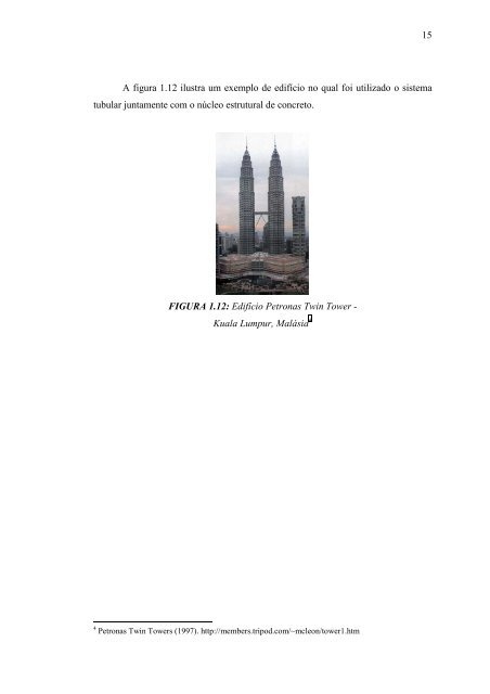
- Page 33: Sistemas tubulares Os sistemas tubu
- Page 37 and 38: a) Pino com cabeça (STUD) b) Perfi
- Page 39 and 40: A norma brasileira NBR 8800 (1986)
- Page 41 and 42: fu é a resistência à ruptura do
- Page 43 and 44: - Para três ou mais conectores por
- Page 45 and 46: TABELA 2.3: Comparação de resulta
- Page 47 and 48: e) O cobrimento lateral de concreto
- Page 49 and 50: FIGURA 2.7: Modelo adotado pelo EUR
- Page 51 and 52: 3.1 INTRODUÇÃO VIGAS MISTAS As vi
- Page 53 and 54: Quando ocorre escorregamento relati
- Page 55 and 56: A estabilidade local e global devem
- Page 57 and 58: O critério que considera a espessu
- Page 59 and 60: L0 L0 0,8L1 L1 0,25(L1+L2) 0,7L2 L2
- Page 61 and 62: Com base na comparação feita na t
- Page 63 and 64: 3.3 DIMENSIONAMENTO SEGUNDO AS PRIN
- Page 65 and 66: C ck = 0, 66 f ba (3.2) T = ( Af )
- Page 67 and 68: hF é a altura nominal da nervura;
- Page 69 and 70: Aa é a área da seção transversa
- Page 71 and 72: MG e ML são momentos fletores devi
- Page 73 and 74: expressões de (3.15) à (3.21). O
- Page 75 and 76: Os valores de momento de inércia e
- Page 77 and 78: de interação completa. A figura 3
- Page 79 and 80: ) Interação Completa - Linha Neut
- Page 81 and 82: Método da Interpolação Linear: E
- Page 83 and 84: cálculo da resistência ao momento
- Page 85 and 86:
pode ser tomado igual a Ec/3 em edi
- Page 87 and 88:
• fy/γRd para a zona comprimida
- Page 89 and 90:
A seguir, são apresentadas as for
- Page 91 and 92:
− 6 = ≥ 10 ∑ L qRd g V h com
- Page 93 and 94:
3.3.2 RESISTÊNCIA AO MOMENTO FLETO
- Page 95 and 96:
a) Taxa de armadura longitudinal ex
- Page 97 and 98:
viga e cada apoio devem ser tais qu
- Page 99 and 100:
No cálculo do momento resistente,
- Page 101 and 102:
a.1) L.N.P na alma: Ocorre quando R
- Page 103 and 104:
V pl , Rd onde A 04 ⎛ f y ⎞ Av
- Page 105 and 106:
O valor do momento resistente à fl
- Page 107 and 108:
− Quando λ LT ≤ 0,4 não é ne
- Page 109 and 110:
momento fletor no apoio, determinad
- Page 111 and 112:
σ σ 0, 4 f A ctm ct s = se + (3.7
- Page 113 and 114:
R = 0, 87A s R = b f a f R = A R =
- Page 115 and 116:
onde M0, δ0 são o momento fletor
- Page 117 and 118:
JOHNSON (1994) apresenta algumas ob
- Page 119 and 120:
100 nos Estados Unidos e Japão, on
- Page 121 and 122:
102 c) Quando for necessária a col
- Page 123 and 124:
104 Após as conferências necessá
- Page 125 and 126:
4.3 COMPORTAMENTO ESTRUTURAL 4.3.1
- Page 127 and 128:
CARREGAMENTO TRANSVERSAL PARAFUSOS
- Page 129 and 130:
• Cisalhamento vertical; • Pun
- Page 131 and 132:
N cf x é a altura da zona comprimi
- Page 133 and 134:
é a largura efetiva da laje, em mm
- Page 135 and 136:
Determinação da Resistência de C
- Page 137 and 138:
τ u , Rk τ u , Rd = (4.13) γ v V
- Page 139 and 140:
4.4.1.3 RESISTÊNCIA AO CISALHAMENT
- Page 141 and 142:
4.4.2 ESTADOS LIMITES DE UTILIZAÇ
- Page 143 and 144:
4.4.2.3 FISSURAÇÃO NO CONCRETO 12
- Page 145 and 146:
- Para vãos internos de lajes cont
- Page 147 and 148:
5.2 CLASSIFICAÇÃO DE PILARES MIST
- Page 149 and 150:
130 Segundo VALLENILLA & BJORHOVDE
- Page 151 and 152:
5.3.2 LIGAÇÕES ENTRE VIGAS E PILA
- Page 153 and 154:
134 teoricamente, empregando a aná
- Page 155 and 156:
136 - Os estribos podem ser soldado
- Page 157 and 158:
138 axialmente comprimidos, de modo
- Page 159 and 160:
140 aderência obtidas experimental
- Page 161 and 162:
5.5.1 NBR 8800 (1986) 142 A norma b
- Page 163 and 164:
N = αφ f c c ck A c Ac é a área
- Page 165 and 166:
Z psn onde = n ∑ i= 1 A sni e yi
- Page 167 and 168:
Z = Z (5.15) pan pcn c pa Z = b h
- Page 169 and 170:
Z = bh − Z − Z (5.30) pan 2 n p
- Page 171 and 172:
) Índice de esbeltez reduzido λ m
- Page 173 and 174:
154 Os pilares mistos abordados pel
- Page 175 and 176:
156 A norma canadense apresenta a e
- Page 177 and 178:
158 O anexo D do EUROCODE 4 apresen
- Page 179 and 180:
NS,c é a força cortante na interf
- Page 181 and 182:
N pl , Rd onde = A a γ f a y Ac 0,
- Page 183 and 184:
) Produto de Rigidez Equivalente -
- Page 185 and 186:
onde χ é o fator de redução da
- Page 187 and 188:
Ponto A Ponto B Ponto C Ponto D hc/
- Page 189 and 190:
d k ( χ d − χ n ) ( χ − χ )
- Page 191 and 192:
onde Aa é a área da seção trans
- Page 193 and 194:
174 A norma britânica apresenta ai
- Page 195 and 196:
176 A norma britânica apresenta a
- Page 197 and 198:
178 O apêndice C desta norma forne
- Page 199 and 200:
Verificação da capacidade local:
- Page 201 and 202:
182 como base o EUROCODE 4: Parte 1
- Page 203 and 204:
184 As principais curvas de incênd
- Page 205 and 206:
186 Os ensaios que possibilitam a c
- Page 207 and 208:
TABELA 6.2: Fator de massividade pa
- Page 209 and 210:
190 DIAS (1998) apresenta diversos
- Page 211 and 212:
tensão (MPa) 250 200 150 100 50 20
- Page 213 and 214:
k Temperatura do aço y , θ k E ,
- Page 215 and 216:
k k TABELA 6.6: Fatores de reduçã
- Page 217 and 218:
198 SILVA (1997) cita que, para tem
- Page 219 and 220:
0,9 para ação permanente favoráv
- Page 221 and 222:
6.4.2.2 RESISTÊNCIA À COMPRESSÃO
- Page 223 and 224:
Se λ ≤ λp,fi : fi, Rd φ fi, a
- Page 225 and 226:
Cmx, Cmy são fatores de equivalên
- Page 227 and 228:
TABELA 6.7: Variação de temperatu
- Page 229 and 230:
1,0 0,8 0,6 0,4 0,2 Q θ θ (20 o Q
- Page 231 and 232:
φfi,a é o coeficiente de resistê
- Page 233 and 234:
214 y fs s y fi a fi y p f b k C f
- Page 235 and 236:
C fi a = (6.38) 0, 85k f b c, θ ck
- Page 237 and 238:
Temperatura (graus Celsius ) 1000 8
- Page 239 and 240:
220 A espessura efetiva da laje hef
- Page 241 and 242:
222 A NBR 14323 recomenda que a esp
- Page 243 and 244:
224 método tabular. As hipóteses
- Page 245 and 246:
TABELA 6.12: Dimensões mínimas da
- Page 247 and 248:
228 Com base em resultados empíric
- Page 249 and 250:
7.2 EXEMPLOS DE VERIFICAÇÃO DE VI
- Page 251 and 252:
• Seção homogeneizada: Coeficie
- Page 253 and 254:
( Af ) = 84 , 0× 25 = 2. 100 T = k
- Page 255 and 256:
236 A tabela 7.1 contém uma compar
- Page 257 and 258:
- Considerando interação completa
- Page 259 and 260:
δ = δ + δ = 1 , 46 + 1, 45 = 2,
- Page 261 and 262:
7.2.2 EXEMPLO 2 242 Este exemplo re
- Page 263 and 264:
Coeficiente de homogeneização: E
- Page 265 and 266:
Momento de inércia: I tr = 2 ( 17,
- Page 267 and 268:
248 425 Sendo a relação largura/e
- Page 269 and 270:
M Rd M Rd ⎛ d R ⎞ a tc = R ⎜
- Page 271 and 272:
M b, Rd = ⎛ γ ⎜ ⎝ γ ⎞ ⎟
- Page 273 and 274:
254 Para levar em conta o efeito da
- Page 275 and 276:
0, 4 × ( 125× 12) = 6, 0cm 100 2
- Page 277 and 278:
258 Comparando os resultados obtido
- Page 279 and 280:
E = 205.000MPa φa f y = f yd = 225
- Page 281 and 282:
262 Para evitar a flambagem local d
- Page 283 and 284:
O momento Mmax,Rd da figura 5.12 é
- Page 285 and 286:
onde χ = 0,938 χ d χ n 1,0 = 0,7
- Page 287 and 288:
268 mistas. Entre esses parâmetros
- Page 289 and 290:
270 que interferem na capacidade re
- Page 291 and 292:
REFERÊNCIAS BIBLIOGRÁFICAS AMERIC
- Page 293 and 294:
274 EUROPEAN COMMITTEE FOR STANDARD
- Page 295 and 296:
276 MELO, C.B.F. (1999). Análise d