Acoplamento Denflex (NEVD)
Acoplamento Denflex (NEVD)
Acoplamento Denflex (NEVD)

Create successful ePaper yourself
Turn your PDF publications into a flip-book with our unique Google optimized e-Paper software.
04/2010
Índice<br />
Index<br />
Generalidades / Generalities.............................................................................................................................. 06<br />
Seleção Detalhada / Selection Procedure........................................................................................................... 07<br />
Formas / Designs ..................... ............................................................................................................................ 08<br />
Forma FLF / Design FLF.... ..................................................................................................................................... 14<br />
Forma FF / Design FF.... ........................................................................................................................................ 15<br />
Forma FF1I / Design FF1I.... .................................................................................................................................. 16<br />
Forma FF2I / Design FF2I.... ................................................................................................................................. 17<br />
Forma FF1L / Design FF1L.... ................................................................................................................................ 18<br />
Forma FF1IL / Design FF1IL.... .............................................................................................................................. 19<br />
Forma FF2L / Design FF2L.... ................................................................................................................................ 20<br />
Forma FF1D / Design FF1D.... ................................................................................................................................ 21<br />
Forma FF1ID / Design FF1ID... ............................................................................................................................... 22<br />
Forma FF1LD / Design FF1LD... ............................................................................................................................. 23<br />
Forma FFI1LD / Design FFI1LD... ........................................................................................................................... 24<br />
Forma FF2D / Design FF2D...... ............................................................................................................................. 25<br />
Forma FF2LD / Design FF2LD... ............................................................................................................................. 26<br />
Forma RF / Design RF.............. .............................................................................................................................. 27<br />
Forma RFI / Design RFI........... .............................................................................................................................. 28<br />
Forma RF1L / Design RF1L..... ............................................................................................................................... 29<br />
Forma RFID / Design RFID... .................................................................................................................................. 30<br />
Forma RF1LD / Design RF1LD. .............................................................................................................................. 31<br />
Forma FEF / Design FEF.......... ............................................................................................................................... 32<br />
Forma FRRF / Design FRRF... ................................................................................................................................. 33<br />
Forma RFFR / Design RFFR... ................................................................................................................................ 34<br />
Forma FFV / Design FFV......... ................................................................................................................................ 35<br />
Forma RFV / Design RFV....... ................................................................................................................................. 36<br />
Forma RR / Design RR.. ........................................................................................................................................ 37<br />
Forma RRV / Design RRV... .................................................................................................................................... 38<br />
Forma FFB / Design FFB....... ................................................................................................................................. 39<br />
Forma RFB / Design RFB ..................................................................................................................................... 40<br />
Forma FFTB / Design FFTB... ................................................................................................................................. 41<br />
Forma RFTB / Design RFTB... ................................................................................................................................ 42<br />
Forma FFAR / Design FFAS.... ............................................................................................................................... 43<br />
Forma FFAS / Design FFAR... ................................................................................................................................. 44<br />
Desalinhamentos Admissíveis / Admissibles Misalignments.............................................................................. 45<br />
Lubrificação / Lubrication.................................................................................................................................. 47<br />
03
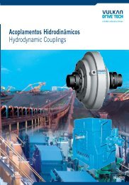
DENFLEX NVD<br />
Generalidades / Generalities<br />
São acoplamentos cuja transmissão de torque se dá através de denteado They are couplings which torque transmission is made through the<br />
interno e externo. A geometria abaulada do denteado externo (cubo) internal and external teeth. Curved External Teeth Geometry<br />
permite uma articulação com o denteado interno (capa). A combinação (Hub) allows articulating with Internal Teeth (Sleeve). This two-<br />
de duas articulações confere ao acoplamento DENFLEX NVD a part articulation provides to DENFLEX NVD coupling the ability to<br />
capacidade de compensar todos os tipos de desalinhamentos em compensate for every type of operating misalignment, as well as for<br />
operação, bem como os desalinhamentos inevitáveis na instalação das unavoidable misalignments that may occur in coupled machines<br />
máquinas acopladas.<br />
installation.<br />
Por serem torcionalmente rídigos, os acoplamentos DENFLEX NVD Due to its torsionally rigid characteristic, the couplings DENFLEX<br />
são especialmente destinados às aplicações com necessidade de NVD are specifically designed for applications requiring torsional<br />
sincronismo torcional, ambientes agressivos a elastômeros (borracha, synchronism, aggressive environments to elastomers (rubber,<br />
poliuretano, etc.) ou reversões constantes em carga. Os acoplamentos polyurethane,etc.) or often load reversions.<br />
DENFLEX NVD são de aço beneficiado, totalmente usinados e DENFLEX NVD couplings are manufactured from hardened steel,<br />
conectados com parafusos de alta resistência, de modo a possuírem fully machined and fastened with high strength bolts for a higher<br />
elevada capacidade de transmissão em relação a tamanho/peso e maior transmission capacity in relation to size/weight and reliability and<br />
confiabilidade e resistência a elevadas cargas repentinas (choques e picos resistance to sudden high loads (shock and torque peaks).<br />
de torque). Os flanges entre as capas dos acoplamentos DENFLEX NVD Flanges between sleeves for DENFLEX NVD couplings are<br />
são dimensionados conforme a norma AGMA 516.01, sendo portanto, dimensioned under AGMA Standard 516.01, so they are<br />
intercambiáveis com a maioria dos acoplamentos de engrenagem. interchangeable with the most of the gearbox couplings.<br />
Estes acoplamentos são adequados para trabalho em ambientes com DENFLEX NVD couplings are designed to work in environments with<br />
temperaturaentre-10ºCe+90ºC,comlubrificação por graxa. Para temperature range between - 10ºC and +90ºC with grease lubrication.<br />
obter mais detalhes, consulte “Lubrificação”, na pág. 47.<br />
See item“lubrication”, on page 47 for more details.<br />
Estão disponíveis em várias formas para atender às necessidades com Several construction forms are available in order to satisfy each<br />
facilidade de manuseio e montagem.<br />
requirement for use and assembling easiness.<br />
Os acoplamentos DENFLEX NVD são fornecidos com película de cera DENFLEX NVD couplings are supplied with an anticorrosion wax<br />
anticorrosiva para proteção superficial.<br />
film for surface protection.<br />
Em caso de dúvidas ou necessidades de acoplamentos especiais consulte In case of doubt or special coupling requirements, please contact us.<br />
a Vulkan.<br />
<strong>Denflex</strong> - NVD - 2010/04<br />
06<br />
Forma/ Design FF<br />
Forma / Design FEF<br />
Reservamo-nos o direito de alterações sem prévio aviso.<br />
Forma / Design RF<br />
We reserve the right of technical alterations without previous notice.
DENFLEX NVD<br />
Seleção Detalhada / Selection Procedure<br />
Na seleção de um acoplamento, é imprescindível considerar o<br />
torquedamáquinaacionadoraeairregularidadedatransmissão,<br />
como também a magnitude das massas a serem aceleradas. Para a<br />
seleção inicial do acoplamento é necessário considerar os fatores de<br />
serviço descritos abaixo, os quais multiplicados pelo torque<br />
nominal da máquina acionadora, determinarão o torque<br />
equivalente (M eq ). O torque nominal (T kn ) do acoplamento<br />
escolhido deverá ser maior ou igual ao torque equivalente.<br />
C x N x Fs<br />
Meq =<br />
n<br />
g) Outros equipamentos<br />
Funcionamento<br />
Diário (horas)/<br />
Daily Operation<br />
(hours)<br />
Temperatura<br />
* Upon Ambiente inquiry (ºc)/<br />
Room<br />
Temperature (ºc)<br />
02<br />
Fator - “F2”<br />
Factor - “F2”<br />
Fator - “F3”<br />
Factor - “F3”<br />
mais de<br />
até<br />
over<br />
till<br />
mais de<br />
até<br />
over<br />
till<br />
-<br />
8<br />
1,0<br />
-<br />
75<br />
1,0<br />
8<br />
16<br />
1,07<br />
75<br />
85<br />
1,1<br />
* Previa consulta/* Upon inquiry<br />
Reservamo-nos o direito de alterações sem prévio aviso.<br />
Meq = torque equivalente (Nm) / equivalent torque (Nm)<br />
N = potência da máquina acionadora (kW/ cv) / driving machine (kW/ HP)<br />
n = rotação de trabalho do acoplamento (rpm) / coupling working rotation (rpm)<br />
Fs = F1xF2xF3xF4= fator de serviço/<br />
F1 x F2 x F3 x F4 = service factor<br />
Tkn = torque nominal do acoplamento (Nm) / coupling nominal torque (Nm)<br />
C = Constante / Constant:<br />
9550 parapotênciaem/<br />
for power in kW<br />
7030 parapotênciaem/<br />
for power in cv<br />
Condição para selecionar acoplamento / For Selecting a Coupling:<br />
Máquina Acionada:/<br />
Driven Machine:<br />
16<br />
24<br />
1,10<br />
85<br />
-<br />
*<br />
In coupling selection, we must consider driving machine torque and<br />
transmission irregularity, as well as the size of masses to be accelerated.<br />
For coupling initial selection we must consider service factors as<br />
described below, which these factors, multiplied by the driving<br />
machine nominal torque, will result the equivalent torque (Meq). The<br />
nominal torque (T kn ) for chosen coupling should be no less than the<br />
equivalent torque.<br />
T kn M eq<br />
Máquinas Acionadas / Driven Machines<br />
a) Com serviço regular e reduzidas massas a acelerar:<br />
- Bombas centrífugas para líquidos,geradores elétricos,ventiladores com N/n ≤<br />
0,05, redutores de velocidade,eixos.<br />
b) Com serviço regular e massas menores a acelerar:<br />
- Máquinas de curvar chapas, elevadores, exaustores, correias transportadoras para<br />
materiais a granel, agitadores para líquidos, máquinas têxteis, turbosopradores e<br />
compressores, ventiladores com N/n = 0,05 a 0,1, ferramentas de máquina com<br />
movimento rotativo.<br />
c) Com serviço irregular e médias massas a acelerar:<br />
- Plainas, sopradores de êmbolo rotativo, fornos giratórios, máquinas impressoras<br />
e secadoras, correias transportadoras para materiais brutos, tambores de tração,<br />
geradores, bobinadores, máquinas para madeira, bombas rotativas para semilíquidos,<br />
tambores de resfriamento, elevadores de carga, misturadores, picadores,<br />
desempenadeiras de capas, agitadores para semi-líquidos, moendas, peneiras<br />
vibratórias,ventiladores com N/n ≥0,1,guinchos.<br />
d) Com serviço irregular e médias massas a acelerar,com carga de impacto adicional:<br />
-Betoneiras, debulhadoras, martelos-pilão, ventiladores de minas, plainas para<br />
metal, ‘‘hollanders’’, transportadores de correntes, trituradoras, bomba-pistão e<br />
compressores com grau de irregularidade de 1:100 a 1:200, guindastes, moinhos<br />
de bolas, eixos de fresadoras, moinhos, elevadores, transportadores de chapas de<br />
aço, bombas de pressão, bombas de fluxo axial, laminador de tubos, tambores de<br />
limpeza, mesas transportadoras de roletes leves, eixos de barcos, moinhos<br />
centrífugos, guinchos de cabo, tambores e fornos de secagem, moinhos de<br />
cilindro,lavadoras,teares,máquinas centrífugas .<br />
e) Com serviço irregular e grandes massas a acelerar, com forte carga de impacto<br />
adicional:<br />
- Escavadoras,usinasdelaminação,trefiladoresdearames,máquinasderolosdeborracha,<br />
moinhos de martelo, martelos, prensas de polpa, calandras, bomba-pistão com<br />
volante, fresas estreitas axial, prensas, engrenagens de sonda rotativa, sacudidores,<br />
cortadores,prensasdeforja,perfuradoras,moendas.<br />
f) Com serviço irregular e massas muito grandes a acelerar,cargas de impacto<br />
adicionais muito fortes:<br />
- Arcos de serra horizontais, compressores e bomba-pistão sem volante, mesas<br />
transportadoras de roletes pesadas, geradores de solda, britadeiras, arcos de serra<br />
de múltiplas lâminas,usina de laminação de metais,prensas de moldar tijolo.<br />
Motor de combustão com 1 a 3 cilindros/Combustion engines with 1 - 3 cylinders<br />
Motor de combustão com 4 ou mais cilindros/Combustion engines with 4 or more cylinders<br />
Motor elétrico ou turbina a vapor/Eletric motor or steam turbines<br />
a) Regular operation and small masses that have to be accelerated:<br />
- Centrifugal pumps for liquid goods, generators, fans N/n 0,05, gear reducer<br />
units, shafting.<br />
b) Regular operation and smaller masses that have to be accelerated:<br />
- Plate bending machines, elevators, exhausters, belt conveyors for bulk materials,<br />
stirrers, liquid goods, light textile machines, turboblowers and compressors, fans<br />
N/n = 0,05 to 0,1, machine tools with rotating motion.<br />
c) Irregular operation and medium masses that have to be accelerated:<br />
- Surface planing and thickening machines, rotaty piston blowers, rotary furnaces,<br />
printing and drying machines, belt conveyors for piece goods, hauling drums,<br />
generators, coilers, wood working machines, centrifugal pumps for semi-liquid<br />
goods, cooling drums, freight elevators, mixers, shredders, ring straightening<br />
machines, stirrers for semi-liquid goods, grinding machines, shaking screens, fans,<br />
N/n 0,1, winches.<br />
d) Irregular operation and medium masses that have to be accelerated and additional<br />
impact loads:<br />
- Concrete mixers, threshing machines, drop hammers, mine fans, planing machines<br />
for metal, hollanders, endless chain transporters, kneading machines, reciprocating<br />
pumps and compressors with degree of irregularity 1:100 to 1:200, cranes, ball mills,<br />
milling courses, mills, passenger elevators, steel plate conveyors, press pumps, axialflow<br />
pumps, pipe mills, tumbling barrels, light roller tables, shafts for ships,<br />
centrifugal mills, cable winches, drying drums and drying kilns, cylinder mills,<br />
washing machines, looms, centrifugal machines.<br />
e) Irregular operation and large masses that have to be accelerated and especially<br />
strong additional impact loads:<br />
- Excavators, lead rolling mills, wire pulls, rubber rolling machines, swing-hammer<br />
mills, hammers, pulp grinders, calendars, reciprocating pumps with light flywheel,<br />
edge mills, presses, rotary-drilling gears, jolters, shears, forging presses, punch<br />
machines, sugarcane breakers.<br />
f) Irregular operation and very large masses that have to be accelerated and<br />
especially strong additional impact loads:<br />
- Horizontal saw frames, piston compressors and reciprocating pumps without<br />
flywheel, heavy roller tables, welding generators, stone breakers, multiple blade<br />
frame saws, rolling mills for metal, brick molding presses.<br />
g) Other equipments<br />
Partidas/hora/<br />
Startings<br />
Per Hour<br />
Modo de<br />
Operação<br />
de acordo com<br />
a Tabela para<br />
Fatores F1/<br />
Depending<br />
On F1 Table<br />
Load Type<br />
a)<br />
b)<br />
c)<br />
d)<br />
e)<br />
f)<br />
g)<br />
01<br />
10<br />
11<br />
20<br />
21<br />
40<br />
41<br />
80<br />
Fator - “F4”/ Factor - “F4”<br />
Fator de Serviço - “F1”/<br />
Service Factor- “F1”<br />
1,5 1,8 2,1<br />
1,6 2,0 2,3<br />
1,7 2,2 2,5<br />
1,9 2,5 2,8<br />
2,1 2,8 3,1<br />
2,4 3,0 3,5<br />
Sob Consulta / Upon inquiry<br />
81<br />
160<br />
sobre<br />
over<br />
160<br />
1 1,10 1,20 1,25 1,40 1,50<br />
1 1,10 1,15 1,20 1,35 1,40<br />
1 1,07 1,15 1,20 1,30 1,40<br />
1 1,07 1,12 1,15 1,20 1,30<br />
1 1,05 1,12 1,15 1,20 1,30<br />
1 1,05 1,10 1,12 1,12 1,12<br />
Previa consulta/Upon inquiry<br />
We reserve the right of technical alterations without previous notice.<br />
07<br />
<strong>Denflex</strong> - NVD - 2010/04
<strong>Denflex</strong> - NVD - 2010/04<br />
DENFLEX NVD<br />
Dados Técnicos / Technical Data<br />
Tamanho<br />
Size<br />
Observações:<br />
- Os pesos e inércias (J), consideram os cubos com pré-furo (d,<br />
d1mín) e espaçador com comprimento mínimo (forma FEF).<br />
- A forma RF não permite desalinhamento radial, não devendo ser<br />
utilizada para unir diretamente dois eixos apoiados. É<br />
normalmente aplicada, usando-se dois acoplamentos e um eixo<br />
flutuante entre eles, montadas como a forma RFFR ou FRRF.<br />
Neste caso, a rotação máxima dependedo comprimento e do peso<br />
do espaçador.Para estas aplicações,consulte aVulkan.<br />
(1) Para rotações superiores,consulte aVulkan.<br />
08 04<br />
110<br />
115<br />
120<br />
125<br />
130<br />
135<br />
140<br />
145<br />
150<br />
155<br />
160<br />
170<br />
180<br />
190<br />
200<br />
210<br />
220<br />
Toque Máx.<br />
Par Max.<br />
Tk max<br />
2500<br />
5500<br />
10625<br />
18750<br />
30250<br />
46250<br />
77500<br />
105000<br />
141500<br />
212500<br />
226250<br />
350000<br />
437500<br />
575000<br />
787500<br />
1037500<br />
1400000<br />
Rotação Máxima<br />
Max. Rotation Speed<br />
n max<br />
8000<br />
6500<br />
5600<br />
5000<br />
4400<br />
3900<br />
3600<br />
3200<br />
2900<br />
2650<br />
2450<br />
2150<br />
1750<br />
1550<br />
1450<br />
1330<br />
1200<br />
Reservamo-nos o direito de alterações sem prévio aviso.<br />
Forma / Design RF Forma / Design FF Forma / Design FEF<br />
Peso<br />
Weight<br />
(kg)<br />
4,0<br />
9,1<br />
15<br />
27<br />
41<br />
65<br />
97<br />
132<br />
193<br />
256<br />
312<br />
500<br />
680<br />
950<br />
1220<br />
1590<br />
2040<br />
J<br />
(Kgm2)<br />
0,0054<br />
0,0204<br />
0,0450<br />
0,1113<br />
0,2098<br />
0,4667<br />
0,8856<br />
1,4399<br />
2,7284<br />
4,2146<br />
5,6461<br />
12,0638<br />
15,7200<br />
27,8300<br />
41,3300<br />
63,4200<br />
98,1900<br />
Remarks:<br />
Peso<br />
Weight<br />
(kg)<br />
3,9<br />
9,0<br />
14<br />
27<br />
40<br />
61<br />
95<br />
130<br />
190<br />
230<br />
300<br />
470<br />
680<br />
940<br />
1250<br />
1620<br />
2070<br />
J<br />
(Kgm2)<br />
0,0052<br />
0,0197<br />
0,0414<br />
0,1070<br />
0,2015<br />
0,4388<br />
0,8460<br />
1,3686<br />
2,6048<br />
3,8940<br />
5,1480<br />
11,1440<br />
18,6500<br />
32,5400<br />
50,9200<br />
75,8900<br />
117,1000<br />
Peso<br />
Weight<br />
(kg)<br />
- Weights and Inertias (J) consider pilot bore hubs (d, d1min) and<br />
spacer with minimum length (FEF design)<br />
- RF design is not allowed for radial misalignment and it is not be used<br />
to connect directly two supported shafts. It is usually applied using<br />
two couplings and a floating shaft between them assembled either as<br />
FRRF or RFFR designs. In this case, maximum speed depends on the<br />
length and spacer weight.Vulkan should be consulted.<br />
(1) For higher speeds, please consultVulkan.<br />
6,5<br />
We reserve the right of technical alterations without previous notice.<br />
14<br />
22<br />
39<br />
56<br />
87<br />
128<br />
170<br />
260<br />
310<br />
360<br />
570<br />
Conforme<br />
projeto<br />
Depending<br />
on project<br />
J<br />
(Kgm2)<br />
0,0097<br />
0,0356<br />
0,0722<br />
0,1791<br />
0,3246<br />
0,7112<br />
1,3007<br />
2,0027<br />
3,9857<br />
5,8523<br />
6,5707<br />
14,6859
DENFLEX NVD<br />
Formas / Designs<br />
FORMA/DESIGN FLF<br />
FORMA/DESIGN FF<br />
FORMA/DESIGN FF1I<br />
FORMA/DESIGN FF2I<br />
FORMA/DESIGN FF1L<br />
FORMA/DESIGN FF1IL<br />
FORMA/DESIGN FF2L<br />
Page/Pág. 14<br />
Page/Pág. 15<br />
Page/Pág. 16<br />
Page/Pág. 17<br />
Page/Pág. 18<br />
Page/Pág. 19<br />
<strong>Acoplamento</strong> composto por dois cubos dentados padrão e uma capa lisa dentada (sem<br />
aparafusamento). Indicado para serviço horizontal. Admite desalinhamentos radial, axial e<br />
angular.<br />
Coupling formed by two standard toothed hubs and a continuous toothed sleeve (without screw).<br />
Indicated for horizontal operation. It allows radial, axial, and angular misalignment.<br />
<strong>Acoplamento</strong> composto por dois cubos dentados padrão e duas capas dentadas padrão, sendo as<br />
duas capas aparafusadas e os dois cubos montados na posição normal, proporcionando o menor<br />
espaçamento entre si. Indicado para serviço horizontal. Admite desalinhamentos radial, axial e<br />
angular.<br />
Coupling formed by two standard toothed hubs and two standard toothed sleeves. The two sleeves are<br />
bolted and hubs are assembled in normal position, providing the least spacing between them.<br />
Indicated for horizontal operation. It allows radial, axial, and angular misalignment.<br />
<strong>Acoplamento</strong> composto por dois cubos dentados padrão e duas capas dentadas padrão, sendo as<br />
duas capas aparafusadas e um cubo montado na posição normal e o outro montado na posição<br />
invertida, proporcionando um espaçamento médio entre si. Indicado para serviço horizontal.<br />
Admite desalinhamentos radial,axial e angular.<br />
Coupling formed by two standard toothed hubs and two standard toothed sleeves. The two sleeves are<br />
bolted, one hub is assembled in normal position and other hub is assembled in reversed position,<br />
providing medium spacing between them. Indicated for horizontal operation. It allows radial, axial,<br />
and angular misalignment.<br />
<strong>Acoplamento</strong> composto por dois cubos dentados padrão e duas capas dentadas padrão, sendo as<br />
duas capas aparafusadas e os dois cubos montados na posição invertida, proporcionando o maior<br />
espaçamento entre si. Indicado para serviço horizontal. Admite desalinhamentos radial, axial e<br />
angular.<br />
Coupling formed by two standard toothed hubs, two standard toothed sleeves. The two sleeves are<br />
bolted and hubs are assembled in reversed position, providing for the greatest spacing among them.<br />
Indicated for horizontal operation. It allows radial, axial, and angular misalignment.<br />
<strong>Acoplamento</strong> composto por um cubo dentado padrão e um cubo dentado longo e duas capas<br />
dentadas padrão, sendo as duas capas aparafusadas e os dois cubos montados na posição normal,<br />
proporcionando um espaçamento médio entre si. Indicado para serviço horizontal. Admite<br />
desalinhamentos radial,axial e angular.<br />
Coupling formed by one standard toothed hub and one long toothed hub, and two standard toothed<br />
sleeves. The two sleeves are bolted and hubs are assembled in normal position, providing a medium<br />
spacing between them. Indicated for horizontal operation. It allows for radial, axial and angular<br />
misalignment.<br />
<strong>Acoplamento</strong> composto por um cubo dentado padrão e um cubo dentado longo e duas<br />
capas dentadas padrão, sendo o cubo padrão montado na posição invertida e o cubo<br />
longo na posição normal,proporcionando o maior espaçamento entre si.Indicado para<br />
serviço horizontal.Admite desalinhamentos radial,axial e angular.<br />
Coupling formed by one standard toothed hub and one long toothed hub, and two standard toothed<br />
sleeves. The standard hub is assembled in reversed position and the long hub in normal position,<br />
providing for the greatest spacing between them. Indicated for horizontal operation. It allows radial,<br />
axial, and angular misalignment.<br />
<strong>Acoplamento</strong> composto por dois cubos dentados longos e duas capas dentadas padrão, sendo as<br />
duas capas aparafusadas e os dois cubos longos montados na posição normal, proporcionando o<br />
maior espaçamento entre si. Indicado para serviço horizontal. Admite desalinhamentos radial,<br />
axial e angular.<br />
Coupling formed by two long toothed hubs, and two standard toothed sleeves. The two sleeves are<br />
bolted and the two long hubs are assembled in normal position, providing for the greatest spacing<br />
between them. Indicated for horizontal operation. It allows radial, axial, and angular 2010/04<br />
-<br />
Page/Pág. 20<br />
misalignment.<br />
NVD -<br />
09<br />
Reservamo-nos o direito de alterações sem prévio aviso. We reserve the right of technical alterations without previous notice.<br />
<strong>Denflex</strong>
<strong>Denflex</strong> - NVD - 2010/04<br />
DENFLEX NVD<br />
Formas / Designs<br />
FORMA/DESIGN FF1D<br />
FORMA/DESIGN FF1ID<br />
FORMA/DESIGN FF1LD<br />
FORMA/DESIGN FFI1LD<br />
FORMA/DESIGN FF2D<br />
FORMA/DESIGN FF2LD<br />
10<br />
Page/Pág. 21<br />
Page/Pág. 22<br />
Page/Pág. 23<br />
Page/Pág. 24<br />
Page/Pág. 25<br />
Page/Pág. 26<br />
Reservamo-nos o direito de alterações sem prévio aviso.<br />
<strong>Acoplamento</strong> composto por dois cubos dentados padrão, uma capa dentada padrão e uma capa<br />
com denteado longo, sendo as duas capas aparafusadas, o cubo padrão montado na posição<br />
normal e o outro montado na posição invertida, proporcionando um espaçamento entre si que<br />
poderá variar de mínimo a médio. Indicado para serviço horizontal e onde haja necessidade de<br />
deslocamento axial moderado.Admite desalinhamentos radial,axial e angular.<br />
Coupling formed by two standard toothed hubs, one standard toothed sleeve and one long toothed<br />
sleeve. The two sleeves are bolted and the standard hub is assembled in normal position and the other<br />
hub in reversed position, providing a spacing between them, which may range from minimum to<br />
medium. Indicated for horizontal operation and where moderate axial displacement is needed. It<br />
allows radial, axial, and angular misalignment.<br />
<strong>Acoplamento</strong> composto por dois cubos dentados padrão, uma capa dentada padrão e uma capa<br />
com denteado longo, sendo as duas capas aparafusadas e os dois cubos montados na posição<br />
invertida, proporcionando um espaçamento entre si que poderá variar de médio a máximo.<br />
Indicado para serviço horizontal e onde haja necessidade de deslocamento axial moderado.<br />
Admite desalinhamentos radial,axial.<br />
Coupling formed by two standard toothed hubs, one standard toothed sleeve and one long toothed<br />
sleeve. The two sleeves are bolted and the two hubs are assembled in reversed position, providing for a<br />
spacing between them, which may range from medium to maximum. Indicated for horizontal<br />
operation and where moderate axial displacement is needed. It allows radial, axial, and angular<br />
misalignment.<br />
<strong>Acoplamento</strong> composto por um cubo dentado padrão, um cubo dentado longo, uma capa<br />
dentada padrão e uma capa com denteado longo, sendo as duas capas aparafusadas e os cubos<br />
montados na posição normal, proporcionando um espaçamento entre si que poderá variar de<br />
mínimo a médio.Indicado para serviço horizontal e onde haja necessidade de deslocamento axial<br />
moderado.Admite desalinhamentos radial,axial e angular.<br />
Coupling formed by one standard toothed hub, one long toothed hub, one standard toothed sleeve and<br />
one long toothed sleeve. The two sleeves are bolted and the hubs are assembled in normal position,<br />
providing for a spacing between them, which may range from minimum to medium. Indicated for<br />
horizontal operation and where moderate axial displacement is needed. It allows radial, axial, and<br />
angular misalignment.<br />
<strong>Acoplamento</strong> composto por um cubo dentado padrão, um cubo dentado longo, uma capa<br />
dentada uma capa padrão com denteado e longo, sendo as duas capas aparafusadas, o cubo padrão montado na<br />
posição invertida e o cubo longo montado na posição normal, proporcionando um espaçamento<br />
entre si que poderá variar de médio a máximo. Indicado para serviço horizontal e onde haja<br />
necessidade de deslocamento axial moderado.Admite desalinhamentos radial,axial e angular.<br />
Coupling formed by one standard toothed hub, one long toothed hub, one standard toothed sleeve and<br />
one long toothed sleeve. The two sleeves are bolted and the standard hub is assembled in reversed<br />
position, and the long hub is assembled in normal position, providing for a spacing between them,<br />
which may range from medium to maximum. Indicated for horizontal operation and where<br />
moderate axial displacement is needed. It allows radial, axial, and angular misalignment.<br />
<strong>Acoplamento</strong> composto por dois cubos dentados padrão e duas capas com denteado longo,sendo<br />
as duas capas aparafusadas e os cubos montados na posição invertida, proporcionando um<br />
espaçamento entre si que poderá variar de mínimo a máximo. Indicado para serviço horizontal e<br />
onde haja necessidade de maior deslocamento axial. Admite desalinhamentos radial, axial e<br />
angular.<br />
Coupling formed by two standard toothed hubs, and two long toothed sleeves. The two sleeves are<br />
bolted and the hubs are assembled in reversed position, providing for a spacing between them, which<br />
may range from minimum to maximum. Indicated for horizontal operation and where the greatest<br />
axial displacement is needed. It allows radial, axial, and angular misalignment.<br />
<strong>Acoplamento</strong> composto por dois cubos dentados longos e duas capas com denteado longo, sendo<br />
as duas capas aparafusadas e os cubos montados na posição padrão proporcionando um<br />
espaçamento entre si, que poderá variar de mínimo a máximo. Indicado para serviço horizontal e<br />
onde haja necessidade de maior deslocamento axial. Admite desalinhamentos radial, axial e<br />
angular.<br />
Coupling formed by two long toothed hubs and two long toothed sleeves. The two sleeves are bolted<br />
and hubs are assembled in standard position, providing for a spacing between them, which may range<br />
from minimum to maximum. Indicated for horizontal operation and where the greatest axial<br />
displacement is needed. It allows radial, axial, and angular misalignment.<br />
We reserve the right of technical alterations without previous notice.
DENFLEX NVD<br />
Formas / Designs<br />
FORMA/DESIGN RF<br />
FORMA/DESIGN RFI<br />
FORMA/DESIGN RF1L<br />
FORMA/DESIGN RFID<br />
FORMA/DESIGN RF1LD<br />
FORMA/DESIGN FEF<br />
Page/Pág. 27<br />
Page/Pág. 28<br />
Page/Pág. 29<br />
Page/Pág. 30<br />
Page/Pág. 31<br />
Page/Pág. 32<br />
Reservamo-nos o direito de alterações sem prévio aviso.<br />
<strong>Acoplamento</strong> composto por um cubo dentado padrão, um cubo rígido padrão e uma capa<br />
dentadapadrão,sendoacapaaparafusadanocuborígidoeocubodentadomontadonaposição<br />
normal,proporcionando o menor espaçamento entre os cubos.Indicado para serviço horizontal.<br />
Admite somente desalinhamentos axial e angular.<br />
Coupling formed by one standard toothed hub, one standard rigid hub, and one standard toothed<br />
sleeve. The sleeve is bolted to the rigid hub, and the toothed hub is assembled in normal position,<br />
providing for the least spacing between the cubes. Indicated for horizontal operation. It only allows<br />
axial and angular misalignment.<br />
<strong>Acoplamento</strong> composto por um cubo dentado padrão, um cubo rígido padrão e uma capa<br />
dentadapadrão,sendoacapaaparafusadanocuborígidoeocubodentadomontadonaposição<br />
invertida, proporcionando um espaçamento médio entre os cubos. Indicado para serviço<br />
horizontal.Admite somente desalinhamentos axial e angular.<br />
Coupling formed by one standard toothed hub, one standard rigid hub and one standard toothed<br />
sleeve. The sleeve is bolted to the rigid hub, and the toothed hub is assembled in reversed position,<br />
providing for a medium spacing between the cubes. Indicated for horizontal operation. It only allows<br />
axial and angular misalignment.<br />
<strong>Acoplamento</strong> composto por um cubo denteado longo, um cubo rígido padrão e uma capa<br />
dentadapadrão,sendoacapaaparafusadanocuborígidoeocubodentadomontadonaposição<br />
invertida, proporcionando um espaçamento médio entre os cubos. Indicado para serviço<br />
horizontal.Admite somente desalinhamentos axial e angular.<br />
Coupling formed by one long toothed hub, one standard rigid hub and one standard toothed sleeve.<br />
The sleeve is bolted to the rigid hub, and the toothed hub is assembled in reversed position, providing<br />
for a medium spacing between the cubes. Indicated for horizontal operation. It only allows axial and<br />
angular misalignment.<br />
<strong>Acoplamento</strong> composto por um cubo dentado padrão, um cubo rígido e uma capa com denteado<br />
longo,sendoacapaaparafusadanocuborígidoeocubodentadomontadonaposição invertida,<br />
proporcionando um espaçamento entre os cubos que poderá variar de mínimo a médio.<br />
Indicado para serviço horizontal e onde haja necessidade de deslocamento axial moderado.<br />
Admite somente desalinhamentos axial e angular.<br />
Coupling formed by one standard toothed hub, one rigid hub and one long toothed sleeve. The sleeve is<br />
bolted to the rigid hub, and the toothed hub is assembled in reversed position, providing for a spacing<br />
between the cubes, which may range from minimum to medium. Indicated for horizontal operation,<br />
and where moderate axial displacement is needed. It only allows axial and angular misalignment.<br />
<strong>Acoplamento</strong> composto por um cubo denteado longo, um cubo rígido e uma capa com denteado<br />
longo,sendoacapaaparafusadanocuborígidoeocubodentadomontadonaposição invertida,<br />
proporcionando um espaçamento entre os cubos que poderá variar de mínimo a médio.<br />
Indicado para serviço horizontal e onde haja necessidade de deslocamento axial moderado.<br />
Admite somente desalinhamentos axial e angular.<br />
Coupling formed by one long toothed hub, one rigid hub, and one long toothed sleeve. The sleeve is<br />
bolted to the rigid hub, and the toothed hub is assembled in reversed position, providing for a spacing<br />
between the cubes, which may range from minimum to medium. Indicated for horizontal operation,<br />
and where moderate axial displacement is needed. It only allows axial and angular misalignment.<br />
<strong>Acoplamento</strong> composto por dois cubos dentados padrão, duas capas dentadas padrão e um<br />
espaçador, sendo as capas aparafusadas no espaçador e os cubos montados na posição normal.<br />
Indicado para serviço horizontal e onde haja necessidade de um maior deslocamento entre as<br />
faces do eixo.Admite desalinhamentos radial,axial e angular.<br />
Coupling formed by two standard toothed hubs, two standard toothed sleeves and a spacer. The<br />
sleeves are bolts to the spacer, and the hubs are assembled in normal position. Indicated for horizontal<br />
operation and where a big displacement between shafts ends is needed. It allows radial, axial, and<br />
angular misalignment.<br />
We reserve the right of technical alterations without previous notice.<br />
11 <strong>Denflex</strong> - NVD - 2010/04
<strong>Denflex</strong> - NVD - 2010/04<br />
DENFLEX NVD<br />
Formas / Designs<br />
FORMA/DESIGN FRRF<br />
FORMA/DESIGN RFFR<br />
FORMA/DESIGN FFV<br />
FORMA/DESIGN RFV<br />
FORMA/DESIGN RR<br />
FORMA/DESIGN RRV<br />
12<br />
Page/Pág. 33<br />
Page/Pág. 34<br />
Page/Pág. 35<br />
Page/Pág. 36<br />
Page/Pág. 37<br />
Page/Pág. 38<br />
Reservamo-nos o direito de alterações sem prévio aviso.<br />
<strong>Acoplamento</strong> composto por dois acoplamentos forma RF e um eixo espaçador maciço, sendo o<br />
espaçador montado de forma chavetado nos cubos rígidos. Indicado para serviço horizontal e<br />
onde haja necessidade de grande afastamento entre as faces de eixo. Admite desalinhamentos<br />
radial,axial e angular.<br />
Coupling formed by two RF couplings, and a solid spacer shaft, which is keyed into the the rigid hubs.<br />
Indicated for horizontal operation and where a big displacement between shafts ends is needed. It<br />
allows radial, axial, and angular misalignment.<br />
<strong>Acoplamento</strong> composto por dois acoplamentos forma RF e um eixo espaçador maciço, sendo o<br />
espaçador montado de forma chavetada nos cubos dentados padrão. Indicado para serviço<br />
horizontal e onde haja necessidade de grande afastamento entre as faces do eixo. Admite<br />
desalinhamentos radial,axial e angular.<br />
Coupling formed by two RF couplings, and a solid spacer shaft, which is keyed into the standard<br />
toothed hubs. Indicated for horizontal operation and where a big displacement between shaft ends is<br />
needed. It allows radial, axial, and angular misalignment.<br />
<strong>Acoplamento</strong> composto por dois cubos dentados padrão, duas capas dentadas padrão e uma<br />
rótula entre as duas capas, sendo as duas capas aparafusadas e os dois cubos montados na posição<br />
normal, proporcionando o menor espaçamento entre si. Indicado para serviço vertical. Admite<br />
desalinhamentos radial,axial e angular.<br />
Coupling formed by two standard toothed hubs, two standard toothed sleeves, and one joint between<br />
the two sleeves, which are bolted, and the two hubs are assembled in normal position, providing for the<br />
least spacing between them. Indicated for vertical operation. It allows radial, axial, and angular<br />
misalignment.<br />
<strong>Acoplamento</strong> composto por um cubo dentado padrão, uma capa dentada padrão, um cubo<br />
rígidoeumarótulaentreacapaeocuborígido,sendoacapaaparafusadanocuborígidoeocubo<br />
montado na posição normal, proporcionando o menor espaçamento entre os cubos. Indicado<br />
para serviço vertical.Admite somente desalinhamentos axial e angular.<br />
Coupling formed by one standard toothed hub, one standard toothed sleeve, one rigid hub, and one<br />
joint between the sleeve and the rigid hub, which the first bolted to the rigid hub, and the hub is<br />
assembled in normal position, providing for the least spacing between the cubes. Indicated for vertical<br />
operation. It only allows axial and angular misalignment.<br />
<strong>Acoplamento</strong> composto por dois cubos rígidos aparafusados entre si. Indicado para serviço<br />
horizontal.Não admite desalinhamento entre os eixos acoplados.<br />
Coupling formed by two rigid hubs bolted together. Indicated for horizontal operation. It allows no<br />
misalignment between the coupled shafts.<br />
<strong>Acoplamento</strong> composto por dois cubos rígidos com roscas radiais, sendo os cubos aparafusados<br />
entre si.Indicado para serviço vertical.Não admite desalinhamento entre os eixos acoplados.<br />
Coupling formed by two rigid hubs with radial screws, which are bolted between themselves.<br />
Indicated for vertical operation. It allows no misalignment between the coupled shafts.<br />
We reserve the right of technical alterations without previous notice.
DENFLEX NVD<br />
Formas / Designs<br />
FORMA/DESIGN FFB<br />
FORMA/DESIGN RFB<br />
FORMA/DESIGN FFTB<br />
FORMA/DESIGN RFTB<br />
FORMA/DESIGN FFAR<br />
FORMA/DESIGN FFAS<br />
Page/Pág. 39<br />
Page/Pág. 40<br />
Page/Pág. 41<br />
Page/Pág. 42<br />
Page/Pág. 43<br />
Page/Pág. 44<br />
Reservamo-nos o direito de alterações sem prévio aviso.<br />
<strong>Acoplamento</strong> composto por dois cubos dentados padrão, duas capas dentadas padrão e uma<br />
polia de freio, sendo a polia de freio aparafusada entre as capas e os dois cubos montados na<br />
posição normal, proporcionando o menor espaçamento entre si. Indicado para serviço<br />
horizontal.Admite desalinhamentos radial,axial e angular.<br />
Coupling formed by two standard toothed hubs, two standard toothed sleeves and one brake pulley.<br />
The brake pulley is bolted between sleeves being the two hubs assembled in the normal position,<br />
providing for the least spacing between them. Indicated for horizontal operation. It allows radial,<br />
axial, and angular misalignment.<br />
<strong>Acoplamento</strong> composto por um cubo dentado padrão, uma capa dentada padrão, um cubo<br />
rígido padrão e uma polia de freio,sendo a polia de freio aparafusada entre a capa e o cubo rígido e<br />
o cubo dentado montado na posição normal, proporcionando o menor espaçamento entre os<br />
cubos.Indicado para serviço horizontal.Admite somente desalinhamentos axial e angular.<br />
Coupling formed by one standard toothed hub, one standard toothed sleeve, one standard rigid hub<br />
and one brake pulley. The brake pulley is bolted between sleeve and rigid hub. The toothed hub is<br />
assembled in the normal position, providing for the least spacing between the cubes. Indicated for<br />
horizontal operation. It only allows radial and angular misalignment.<br />
<strong>Acoplamento</strong> composto por um cubo dentado padrão, um cubo dentado especial, duas capas<br />
dentadas padrão e um disco de freio, sendo o disco de freio aparafusado entre as capas e<br />
mantendo-o posicionado pelo cubo especial. Os cubos são montados na posição normal,<br />
proporcionando o menor espaçamento entre si. Indicado para serviço horizontal. Admite<br />
desalinhamentos radial,axial e angular.<br />
Coupling formed by one standard toothed hub, one special toothed hub, two standard toothed sleeves<br />
and one brake disc. The brake disc is bolted between sleeves being the disc brake maintained in<br />
position by the special hub. The hubs are assembled in normal position, providing for the least<br />
spacing among between the hubs. Indicated for horizontal operation. It allows radial, axial, and<br />
angular misalignment.<br />
<strong>Acoplamento</strong> composto por um cubo dentado padrão, uma capa dentada padrão, um cubo<br />
rígido padrão e um disco de freio, sendo o disco de freio aparafusado entre a capa e o cubo rígido e<br />
o cubo dentado montado na posição normal, proporcionando o menor espaçamento entre os<br />
cubos.Indicado para serviço horizontal.Admite somente desalinhamentos axial e angular.<br />
Coupling formed by one standard toothed hub, one standard toothed sleeve, one standard rigid hub<br />
and one brake disc. The brake disc is bolted between the sleeve and the rigid hub. The toothed hub is<br />
assembled in normal position, providing for the least spacing among between the cubes. Indicated for<br />
horizontal operation. It only allows axial and angular misalignment.<br />
<strong>Acoplamento</strong> de acoplar/desacoplar estaticamente composto por cubos dentados especiais,<br />
capas dentadas especiais e um colar de bronze, sendo as capas aparafusadas entre si e os cubos<br />
montados na posição normal, proporcionando o menor espaçamento entre si. Indicado para<br />
serviço horizontal e onde se requer acoplar/desacoplar estaticamente a máquina acionadora da<br />
acionada.Admite desalinhamentos radial,axial e angular.<br />
Engageable/disengageable coupling statically formed by special toothed hubs, special toothed sleeves<br />
and one bronze ring. The sleeves are bolted between themselves and hubs are assembled in normal<br />
position, providing for the least spacing between the hubs. Indicated for horizontal operation and<br />
where it is required for statically engaging/disengaging the driving machine from the driven one. It<br />
allows radial, axial, and angular misalignment.<br />
<strong>Acoplamento</strong> de segurança através de pino de cisalhamento, composto por cubos dentados padrão,<br />
capas dentadas padrão, dois flanges, buchas de deslizamento e pinos de cisalhamento, sendo os<br />
flanges aparafusados entre as capas e os cubos montados na posição normal, proporcionando o<br />
menor espaçamento entre si. Indicado para serviço horizontal e onde se requer proteger as máquinas<br />
acopladas contra picos excessivos de carga.Admite desalinhamentos radial,axial e angular.<br />
Safety coupling through shear pin formed by standard toothed hubs, standard toothed sleeves, two<br />
flanges, sliding bushings, shear pins. The flanges are bolted between sleeves and hubs are assembled in<br />
normal position, providing for the least spacing between the hubs. Indicated for horizontal operation<br />
and where it is required for protecting coupled machines against load peaks in excess. It allows radial,<br />
axial, and angular misalignment.<br />
We reserve the right of technical alterations without previous notice.<br />
13 <strong>Denflex</strong> - NVD - 2010/04
<strong>Denflex</strong> - NVD - 2010/04<br />
DENFLEX NVD<br />
Forma / Design FLF<br />
Ød1<br />
l2<br />
K<br />
Observações:<br />
l1<br />
110 1000 2500<br />
115 2200 5500<br />
120 4250 10625<br />
125 7500 18750<br />
130 12100 30250<br />
135 18500 46250<br />
140 31000 77500<br />
145 42000 105000<br />
150 56600 141500<br />
155 85000 212500<br />
160 90500 226250<br />
170 140000 350000<br />
L2<br />
L1<br />
S1<br />
Até tam. 135<br />
Up to size 135<br />
Torque Torque Rot. d<br />
Tam. Nom. Máx. Máx.<br />
1<br />
Size Tkn Tkmax Nmax (2)<br />
(Nm) (Nm) (rpm) mín<br />
8000<br />
6500<br />
5600<br />
5000<br />
4400<br />
3900<br />
3600<br />
3200<br />
2900<br />
2650<br />
2450<br />
2150<br />
1-Osfurosd1<br />
máx.consideramchavetaconformenormaDIN6885/1.<br />
Para chavetas conforme AGMA 9002-A86 (quadrada ou<br />
retangular) observar a seção mínima do cubo no canto do rasgo<br />
de chaveta.<br />
2- Quando não especificados os diâmetros dos furos e rasgos de<br />
chaveta, os acoplamentos serão fornecidos com furação mínima<br />
(d1 min).<br />
3-Énecessário o espaço “K” para permitir o correto alinhamento e<br />
para desconectar as máquinas acopladas.<br />
14<br />
l1<br />
12<br />
18<br />
25<br />
30<br />
35<br />
50<br />
50<br />
50<br />
50<br />
50<br />
50<br />
50<br />
l2<br />
ØD2<br />
(1)<br />
máx<br />
48<br />
65<br />
77<br />
100<br />
119<br />
132<br />
164<br />
182<br />
200<br />
225<br />
238<br />
290<br />
ØD<br />
94<br />
117<br />
136<br />
166<br />
192<br />
212<br />
270<br />
305<br />
340<br />
370<br />
410<br />
470<br />
Reservamo-nos o direito de alterações sem prévio aviso.<br />
D D 2<br />
68<br />
87<br />
102<br />
129<br />
152<br />
171<br />
207<br />
230<br />
250<br />
277<br />
295<br />
347<br />
Ød1<br />
L 1<br />
89<br />
102<br />
127<br />
159<br />
187<br />
219<br />
247<br />
278<br />
314<br />
344<br />
384<br />
452<br />
Remarks:<br />
K<br />
l1<br />
L2<br />
L1<br />
S1<br />
A partir do tam. 140<br />
From size 140<br />
L 2<br />
71<br />
84<br />
91<br />
106<br />
122<br />
156<br />
143<br />
160<br />
178<br />
186<br />
202<br />
222<br />
l 1<br />
43<br />
49,5<br />
62<br />
77<br />
91<br />
106,5<br />
120,5<br />
135<br />
153<br />
168<br />
188<br />
221<br />
Onde não indicado,considerar unidades em mm. Where not specified, consider units in mm.<br />
1-The<br />
d1 max bores consider keyways according to DIN 6885/1.<br />
For keyways according to AGMA 9002-A86 (square or rectangular<br />
standard) to check the minimum distance of the hub up to the<br />
keyway corner.<br />
2- When bore diameters and keyways are not defined, couplings shall<br />
be supplied with pilot bores (d1 min).<br />
3- Distance “K” is required in order to allow the right alignment and<br />
to disconnect coupled machines.<br />
l1<br />
l2<br />
l 2<br />
9<br />
9<br />
18<br />
26,5<br />
32,5<br />
31,5<br />
52<br />
39<br />
44<br />
55<br />
67<br />
86<br />
ØD2<br />
ØD<br />
S 1<br />
3<br />
3<br />
3<br />
5<br />
5<br />
6<br />
6<br />
8<br />
8<br />
8<br />
8<br />
10<br />
We reserve the right of technical alterations without previous notice.<br />
(3)<br />
K<br />
15<br />
16<br />
22<br />
25<br />
30<br />
35<br />
40<br />
45<br />
50<br />
55<br />
60<br />
70
DENFLEX NVD<br />
Forma / Design FF<br />
Tam.<br />
Size<br />
110<br />
115<br />
120<br />
125<br />
130<br />
135<br />
140<br />
145<br />
150<br />
155<br />
160<br />
170<br />
180<br />
190<br />
200<br />
210<br />
220<br />
Torque<br />
Nom.<br />
T kn<br />
(Nm)<br />
1000<br />
2200<br />
4250<br />
7500<br />
12100<br />
18500<br />
31000<br />
42000<br />
56600<br />
85000<br />
90500<br />
140000<br />
175000<br />
230000<br />
315000<br />
415000<br />
560000<br />
Onde não indicado,considerar unidades em mm. Where not specified, consider units in mm.<br />
Observações:<br />
l5<br />
Ød1 K<br />
Torque<br />
Máx.<br />
Tkmax (Nm)<br />
2500<br />
5500<br />
10625<br />
18750<br />
30250<br />
46250<br />
77500<br />
105000<br />
141500<br />
212500<br />
226250<br />
350000<br />
437500<br />
575000<br />
787500<br />
1037500<br />
1400000<br />
l1<br />
l3<br />
Rot.<br />
Máx.<br />
Nmax (rpm)<br />
8000<br />
6500<br />
5600<br />
5000<br />
4400<br />
3900<br />
3600<br />
3200<br />
2900<br />
2650<br />
2450<br />
2150<br />
1750<br />
1550<br />
1450<br />
1330<br />
1200<br />
l2 l2<br />
L1<br />
Até tam. 170<br />
Up to size 170<br />
D D D<br />
1 2<br />
1-Os<br />
furos d1 máx. consideram chaveta conforme norma DIN6885/1.<br />
Para chavetas conforme AGMA 9002-A86 (quadrada ou<br />
retangular) observar a seção mínima do cubo no canto do rasgo<br />
de chaveta.<br />
2 - Quando não especificados os diâmetros dos furos e rasgos de<br />
chaveta, os acoplamentos serão fornecidos com furação mínima<br />
(d1 min).<br />
3-Énecessário o espaço“K”para permitir o correto alinhamento e<br />
para desconectar as máquinas acopladas.<br />
S<br />
(2)<br />
mín<br />
12<br />
18<br />
25<br />
30<br />
35<br />
50<br />
50<br />
50<br />
50<br />
50<br />
50<br />
50<br />
100<br />
110<br />
125<br />
135<br />
150<br />
l1<br />
d 1<br />
(1)<br />
máx<br />
48<br />
65<br />
77<br />
100<br />
119<br />
132<br />
164<br />
182<br />
200<br />
225<br />
238<br />
290<br />
290<br />
330<br />
380<br />
400<br />
450<br />
ØD2<br />
116<br />
152<br />
178<br />
213<br />
240<br />
280<br />
318<br />
346<br />
390<br />
425<br />
457<br />
527<br />
590<br />
660<br />
711<br />
775<br />
838<br />
Reservamo-nos o direito de alterações sem prévio aviso.<br />
ØD1<br />
ØLKR (nº de furos)<br />
(nº of holes)<br />
ØD<br />
83<br />
105<br />
126<br />
155<br />
180<br />
211<br />
245<br />
274<br />
306<br />
334<br />
366<br />
425<br />
571<br />
641<br />
698<br />
749<br />
825<br />
68<br />
87<br />
102<br />
129<br />
152<br />
171<br />
207<br />
230<br />
250<br />
277<br />
295<br />
347<br />
360<br />
412<br />
465<br />
495<br />
552<br />
ØD2<br />
L 1<br />
89<br />
102<br />
127<br />
159<br />
187<br />
219<br />
247<br />
278<br />
314<br />
344<br />
384<br />
452<br />
508<br />
565<br />
622<br />
680<br />
718<br />
Ød1<br />
Remarks:<br />
K<br />
l 1<br />
43<br />
49,5<br />
62<br />
77<br />
91<br />
106,5<br />
120,5<br />
135<br />
153<br />
168<br />
188<br />
221<br />
249<br />
276<br />
305<br />
333<br />
352<br />
l5<br />
l 2<br />
l1<br />
16<br />
19<br />
19<br />
23<br />
23<br />
28<br />
28<br />
28<br />
38<br />
38<br />
25,4<br />
28,5<br />
32<br />
38<br />
44,5<br />
51<br />
54<br />
l3<br />
l2<br />
L1<br />
S<br />
l1<br />
A partir do tam. 180<br />
From size 180<br />
l 3<br />
27<br />
31<br />
42<br />
54<br />
64<br />
71<br />
82<br />
96<br />
109<br />
122<br />
136<br />
165<br />
183<br />
200<br />
217<br />
246<br />
259<br />
l 5<br />
4,5<br />
4,5<br />
4,5<br />
4,5<br />
4,5<br />
4,5<br />
5<br />
5<br />
5<br />
5<br />
6<br />
7<br />
11<br />
17,5<br />
17<br />
17<br />
18<br />
ØLK ( nº de furos)<br />
( nº of holes)<br />
1-The<br />
d1 max bores consider keyways according to DIN 6885/1.<br />
For keyways according to AGMA 9002-A86 (square or rectangular<br />
standard) to check the minimum distance of the hub up to the<br />
keyway corner.<br />
2- When bore diameters and keyways are not defined, couplings shall<br />
be supplied with pilot bores (d1 min).<br />
3- Distance “K” is required in order to allow the right alignment and<br />
to disconnect coupled machines.<br />
l3<br />
l2<br />
S<br />
3<br />
3<br />
3<br />
5<br />
5<br />
6<br />
6<br />
8<br />
8<br />
8<br />
8<br />
10<br />
10<br />
13<br />
12<br />
14<br />
14<br />
(3)<br />
K<br />
12<br />
13<br />
17<br />
20<br />
23<br />
32<br />
34<br />
42<br />
42<br />
45<br />
60<br />
72<br />
80<br />
80<br />
95<br />
105<br />
105<br />
ØD1<br />
We reserve the right of technical alterations without previous notice.<br />
ØD<br />
LKR N<br />
95,25<br />
122,22<br />
149,22<br />
180,98<br />
206,37<br />
241,30<br />
279,40<br />
304,80<br />
342,90<br />
368,30<br />
400,05<br />
463,55<br />
527,00<br />
590,50<br />
641,35<br />
698,50<br />
762,00<br />
6<br />
8<br />
6<br />
6<br />
8<br />
8<br />
8<br />
10<br />
8<br />
14<br />
14<br />
16<br />
16<br />
18<br />
18<br />
18<br />
18<br />
15 <strong>Denflex</strong> - NVD - 2010/04
<strong>Denflex</strong> - NVD - 2010/04<br />
DENFLEX NVD<br />
Forma / Design FF1I<br />
Tam.<br />
Size<br />
110<br />
115<br />
120<br />
125<br />
130<br />
135<br />
140<br />
145<br />
150<br />
155<br />
160<br />
170<br />
180<br />
190<br />
200<br />
210<br />
220<br />
l5<br />
Ød1 K<br />
1000<br />
2200<br />
4250<br />
7500<br />
12100<br />
18500<br />
31000<br />
42000<br />
56600<br />
85000<br />
90500<br />
140000<br />
175000<br />
230000<br />
315000<br />
415000<br />
560000<br />
l1<br />
l3 l2 l2<br />
2500<br />
5500<br />
10625<br />
18750<br />
30250<br />
46250<br />
77500<br />
105000<br />
141500<br />
212500<br />
226250<br />
350000<br />
437500<br />
575000<br />
787500<br />
1037500<br />
1400000<br />
S<br />
L1<br />
8000<br />
6500<br />
5600<br />
5000<br />
4400<br />
3900<br />
3600<br />
3200<br />
2900<br />
2650<br />
2450<br />
2150<br />
1750<br />
1550<br />
1450<br />
1330<br />
1200<br />
l1<br />
Até tam. 170<br />
Up to size 170<br />
12<br />
18<br />
25<br />
30<br />
35<br />
50<br />
50<br />
50<br />
50<br />
50<br />
50<br />
50<br />
100<br />
110<br />
125<br />
135<br />
150<br />
K1<br />
K<br />
l6 l5<br />
48<br />
65<br />
77<br />
100<br />
119<br />
132<br />
164<br />
182<br />
200<br />
225<br />
238<br />
290<br />
290<br />
330<br />
380<br />
400<br />
450<br />
ØD2<br />
D D D<br />
1 2<br />
116<br />
152<br />
178<br />
213<br />
240<br />
280<br />
318<br />
346<br />
390<br />
425<br />
457<br />
527<br />
590<br />
660<br />
711<br />
775<br />
838<br />
Onde não indicado,considerar unidades em mm.<br />
Observações:<br />
ØD1<br />
ØLKR ( nº de furos)<br />
(nº of holes)<br />
ØD<br />
83<br />
105<br />
126<br />
155<br />
180<br />
211<br />
245<br />
274<br />
306<br />
334<br />
366<br />
425<br />
571<br />
641<br />
698<br />
749<br />
825<br />
68<br />
87<br />
102<br />
129<br />
152<br />
171<br />
207<br />
230<br />
250<br />
277<br />
295<br />
347<br />
360<br />
412<br />
465<br />
495<br />
552<br />
1-Os<br />
furos d1 máx. consideram chaveta conforme norma DIN6885/1.<br />
Para chavetas conforme AGMA 9002-A86 (quadrada ou<br />
retangular) observar a seção mínima do cubo no canto do rasgo<br />
de chaveta.<br />
2 - Quando não especificados os diâmetros dos furos e rasgos de<br />
chaveta, os acoplamentos serão fornecidos com furação mínima<br />
(d1 min).<br />
3 - São necessários os espaços “K” e “K1” para permitir o correto<br />
alinhamento e para desconectar as máquinas acopladas.<br />
16<br />
Torque<br />
Nom.<br />
T kn<br />
(Nm)<br />
Torque<br />
Máx.<br />
Tkmax (Nm)<br />
Rot.<br />
Máx.<br />
N max<br />
(rpm)<br />
(2)<br />
mín<br />
d 1<br />
(1)<br />
máx<br />
Reservamo-nos o direito de alterações sem prévio aviso.<br />
ØD2<br />
L 1<br />
Ød1<br />
96,5<br />
112<br />
146<br />
186<br />
220<br />
248<br />
285<br />
327<br />
371<br />
412<br />
461<br />
553<br />
615<br />
675<br />
738<br />
826<br />
870<br />
l 1<br />
l1<br />
l 2<br />
43 16<br />
49,5 19<br />
62 19<br />
77 23<br />
91 23<br />
106,5 28<br />
120,5 28<br />
135 28<br />
153 38<br />
168 38<br />
188 25,4<br />
221 28,5<br />
249 32<br />
276 38<br />
305 44,5<br />
333 51<br />
352 54<br />
l3 l3<br />
K1<br />
l2 l2 l6<br />
l 3<br />
27<br />
31<br />
42<br />
54<br />
64<br />
71<br />
82<br />
96<br />
109<br />
122<br />
136<br />
165<br />
183<br />
200<br />
217<br />
246<br />
259<br />
S<br />
L1<br />
l 5<br />
l 6<br />
l1<br />
4,5 12 10,5<br />
4,5 14,5 13<br />
4,5 23,5 22<br />
4,5 31,5 32<br />
4,5 37,5 38<br />
4,5 33,5 35<br />
5 43 44<br />
5 54 57<br />
5 62 65<br />
5 73 76<br />
6 83 85<br />
7 108 111<br />
11 118 117<br />
17,5 127,5 123<br />
17 133 128<br />
18 164 160<br />
18 170 166<br />
Where not specified, consider units in mm.<br />
Remarks:<br />
A partir do tam. 180<br />
From size 180<br />
ØLKR (nº de furos)<br />
(nº of holes)<br />
ØD1<br />
(3) (3)<br />
S K K<br />
1<br />
12<br />
13<br />
17<br />
20<br />
23<br />
32<br />
34<br />
42<br />
42<br />
45<br />
60<br />
72<br />
80<br />
80<br />
95<br />
105<br />
105<br />
19,5<br />
23<br />
36<br />
47<br />
56<br />
61<br />
72<br />
91<br />
99<br />
113<br />
137<br />
173<br />
187<br />
190<br />
211<br />
251<br />
257<br />
ØD<br />
LKR N<br />
95,25<br />
122,22<br />
149,22<br />
180,98<br />
206,37<br />
241,30<br />
279,40<br />
304,80<br />
342,90<br />
368,30<br />
400,05<br />
463,55<br />
527,00<br />
590,50<br />
641,35<br />
698,50<br />
762,00<br />
6<br />
8<br />
6<br />
6<br />
8<br />
8<br />
8<br />
10<br />
8<br />
14<br />
14<br />
16<br />
16<br />
18<br />
18<br />
18<br />
18<br />
1-The<br />
d1 max bores consider keyways according to DIN 6885/1.<br />
For keyways according to AGMA 9002-A86 (square or rectangular<br />
standard) to check the minimum distance of the hub up to the<br />
keyway corner.<br />
2- When bore diameters and keyways are not defined, couplings shall<br />
be supplied with pilot bores (d1 min).<br />
3- Distances “K” and “K1” are required in order to allow the right<br />
alignment and to disconnect coupled machines.<br />
We reserve the right of technical alterations without previous notice.
DENFLEX NVD<br />
Forma / Design FF2I<br />
Tam.<br />
Size<br />
110<br />
115<br />
120<br />
125<br />
130<br />
135<br />
140<br />
145<br />
150<br />
155<br />
160<br />
170<br />
180<br />
190<br />
200<br />
210<br />
220<br />
Ød1<br />
K1<br />
Torque<br />
Nom.<br />
T kn<br />
(Nm)<br />
1000<br />
2200<br />
4250<br />
7500<br />
12100<br />
18500<br />
31000<br />
42000<br />
56600<br />
85000<br />
90500<br />
140000<br />
175000<br />
230000<br />
315000<br />
415000<br />
560000<br />
Até tam. 170<br />
Up to size 170<br />
Onde não indicado,considerar unidades em mm.<br />
Observações:<br />
l1<br />
l3<br />
l2<br />
l6 l6<br />
Torque<br />
Máx.<br />
Tkmax (Nm)<br />
2500<br />
5500<br />
10625<br />
18750<br />
30250<br />
46250<br />
77500<br />
105000<br />
141500<br />
212500<br />
226250<br />
350000<br />
437500<br />
575000<br />
787500<br />
1037500<br />
1400000<br />
L1<br />
l2<br />
S<br />
Rot.<br />
Máx.<br />
N max<br />
(rpm)<br />
8000<br />
6500<br />
5600<br />
5000<br />
4400<br />
3900<br />
3600<br />
3200<br />
2900<br />
2650<br />
2450<br />
2150<br />
1750<br />
1550<br />
1450<br />
1330<br />
1200<br />
1-Os<br />
furos d1 máx.consideram chaveta conforme norma DIN6885/1.<br />
Para chavetas conforme AGMA 9002-A86 (quadrada ou<br />
retangular) observar a seção mínima do cubo no canto do rasgo<br />
de chaveta.<br />
2 - Quando não especificados os diâmetros dos furos e rasgos de<br />
chaveta, os acoplamentos serão fornecidos com furação mínima<br />
(d1 min).<br />
3-Énecessário o espaço“K”para permitir o correto alinhamento e<br />
para desconectar as máquinas acopladas.<br />
l3<br />
(2)<br />
mín<br />
d 1<br />
12<br />
18<br />
25<br />
30<br />
35<br />
50<br />
50<br />
50<br />
50<br />
50<br />
50<br />
50<br />
100<br />
110<br />
125<br />
135<br />
150<br />
l1<br />
(1)<br />
máx<br />
48<br />
65<br />
77<br />
100<br />
119<br />
132<br />
164<br />
182<br />
200<br />
225<br />
238<br />
290<br />
290<br />
330<br />
380<br />
400<br />
450<br />
K1<br />
ØD2<br />
Reservamo-nos o direito de alterações sem prévio aviso.<br />
ØD1<br />
ØLK<br />
( nº de furos)<br />
(nº of hles)<br />
ØD<br />
D D D<br />
1 2<br />
116<br />
152<br />
178<br />
213<br />
240<br />
280<br />
318<br />
346<br />
390<br />
425<br />
457<br />
527<br />
590<br />
660<br />
711<br />
775<br />
838<br />
83<br />
105<br />
126<br />
155<br />
180<br />
211<br />
245<br />
274<br />
306<br />
334<br />
366<br />
425<br />
571<br />
641<br />
698<br />
749<br />
825<br />
68<br />
87<br />
102<br />
129<br />
152<br />
171<br />
207<br />
230<br />
250<br />
277<br />
295<br />
347<br />
360<br />
412<br />
465<br />
495<br />
552<br />
ØD2<br />
L 1<br />
Ød1<br />
104<br />
122<br />
165<br />
213<br />
253<br />
277<br />
323<br />
376<br />
428<br />
480<br />
538<br />
654<br />
722<br />
785<br />
854<br />
972<br />
1022<br />
Where not specified, consider units in mm.<br />
Remarks:<br />
K1<br />
l6<br />
l 1<br />
43<br />
49,5<br />
62<br />
77<br />
91<br />
106,5<br />
120,5<br />
135<br />
153<br />
168<br />
188<br />
221<br />
249<br />
276<br />
305<br />
333<br />
352<br />
l1<br />
l 2<br />
16<br />
19<br />
19<br />
23<br />
23<br />
28<br />
28<br />
28<br />
38<br />
38<br />
25,4<br />
28,5<br />
32<br />
38<br />
44,5<br />
51<br />
54<br />
l3<br />
L1<br />
S<br />
A partir do tam. 180<br />
From size 180<br />
l 3<br />
27<br />
31<br />
42<br />
54<br />
64<br />
71<br />
82<br />
96<br />
109<br />
122<br />
136<br />
165<br />
183<br />
200<br />
217<br />
246<br />
259<br />
l 6<br />
1-The<br />
d1 max bores consider keyways according to DIN 6885/1.<br />
For keyways according to AGMA 9002-A86 (square or rectangular<br />
standard) to check the minimum distance of the hub up to the<br />
keyway corner.<br />
2- When bore diameters and keyways are not defined, couplings shall<br />
be supplied with pilot bores (d1 min).<br />
3- Distance “K” is required in order to allow the right alignment and<br />
to disconnect coupled machines.<br />
l3<br />
12<br />
14,5<br />
23,5<br />
31,5<br />
37,5<br />
33,5<br />
43<br />
54<br />
62<br />
73<br />
83<br />
108<br />
118<br />
127,5<br />
133<br />
164<br />
170<br />
l1<br />
K1<br />
l6<br />
(3)<br />
K<br />
1<br />
ØLKR (nºde furos)<br />
(nº of holes)<br />
ØD1<br />
We reserve the right of technical alterations without previous notice.<br />
S<br />
18<br />
23<br />
41<br />
59<br />
71<br />
64<br />
82<br />
106<br />
122<br />
144<br />
162<br />
212<br />
224<br />
233<br />
244<br />
306<br />
318<br />
19,5<br />
23<br />
36<br />
47<br />
56<br />
61<br />
72<br />
91<br />
99<br />
113<br />
137<br />
173<br />
187<br />
190<br />
211<br />
251<br />
257<br />
ØD<br />
LKR N<br />
95,25<br />
122,22<br />
149,22<br />
180,98<br />
206,37<br />
241,30<br />
279,40<br />
304,80<br />
342,90<br />
368,30<br />
400,05<br />
463,55<br />
527,00<br />
590,50<br />
641,35<br />
698,50<br />
762,00<br />
6<br />
8<br />
6<br />
6<br />
8<br />
8<br />
8<br />
10<br />
8<br />
14<br />
14<br />
16<br />
16<br />
18<br />
18<br />
18<br />
18<br />
17 <strong>Denflex</strong> - NVD - 2010/04
<strong>Denflex</strong> - NVD - 2010/04<br />
DENFLEX NVD<br />
Forma / Design FF1L<br />
Tam.<br />
Size<br />
Ød1<br />
K1<br />
l7<br />
l<br />
l3<br />
L1<br />
l2 l2<br />
S<br />
l3<br />
Até tam. 170<br />
Up to size 170<br />
110 1000 2500 8000 12<br />
115 2200 5500 6500 18<br />
120 4250 10625 5600 25<br />
125 7500 18750 5000 30<br />
130 12100 30250 4400 35<br />
135 18500 46250 3900 50<br />
140 31000 77500 3600 50<br />
145 42000 105000 3200 50<br />
150 56600 141500 2900 50<br />
155 85000 212500 2650 50<br />
160 90500 226250 2450 50<br />
170 140000 350000 2150 50<br />
180 175000 437500 1750 100<br />
190 230000 575000 1550 110<br />
200 315000 787500 1450 125<br />
210 415000 1037500 1330 135<br />
220 560000 1400000 1200 150<br />
Onde não indicado,considerar unidades em mm.<br />
Observações:<br />
l1<br />
l5<br />
K K1<br />
l7<br />
ØD2<br />
ØD1<br />
ØLKR (nº de furos)<br />
(nº of holes)<br />
ØD<br />
D D D<br />
1 2<br />
1-Os<br />
furos d1 máx. consideram chaveta conforme norma DIN6885/1.<br />
Para chavetas conforme AGMA 9002-A86 (quadrada ou<br />
retangular) observar a seção mínima do cubo no canto do rasgo<br />
de chaveta.<br />
2 - Quando não especificados os diâmetros dos furos e rasgos de<br />
chaveta, os acoplamentos serão fornecidos com furação mínima<br />
(d1 min).<br />
3 - São necessários os espaços “K” e “K1” para permitir o correto<br />
alinhamento e para desconectar as máquinas acopladas.<br />
18<br />
Torque<br />
Nom.<br />
T kn<br />
(Nm)<br />
Torque<br />
Máx.<br />
Tkmax (Nm)<br />
Rot.<br />
Máx.<br />
N max<br />
(rpm)<br />
(2)<br />
mín<br />
d 1<br />
(1)<br />
máx<br />
Reservamo-nos o direito de alterações sem prévio aviso.<br />
L 1<br />
ØD2<br />
Ød1<br />
l l 1<br />
48 116 83 68 155,5 102 43 16<br />
65 152 105 87 176,5 114 49,5 19<br />
77 178 126 102 214 130 62 19<br />
100 213 155 129 258 149 77 23<br />
119 240 180 152 294 165 91 23<br />
132 280 211 171 325,5 184 106,5 28<br />
164 318 245 207 367,5 203 120,5 28<br />
182 346 274 230 436 244 135 28<br />
200 390 306 250 513 295 153 38<br />
225 425 334 277 542 298 168 38<br />
238 457 366 295 578 305 188 25,4<br />
290 527 425 347 642 310 221 28,5<br />
290 590 571 360 839 473 249 32<br />
330 660 641 412 923 524 276 38<br />
380 711 698 465 1012 579 305 44,5<br />
400 775 749 508,5 1125 632 333 51<br />
450 838 825 552 1186 668 352 54<br />
A partir do tam. 180<br />
From size 180<br />
Where not specified, consider units in mm.<br />
Remarks:<br />
l<br />
l 2<br />
l 3<br />
27<br />
31<br />
42<br />
54<br />
64<br />
71<br />
82<br />
96<br />
109<br />
122<br />
136<br />
165<br />
183<br />
200<br />
217<br />
246<br />
259<br />
l3<br />
L1<br />
S<br />
l 5<br />
4,5<br />
4,5<br />
4,5<br />
4,5<br />
4,5<br />
4,5<br />
5<br />
5<br />
5<br />
5<br />
6<br />
7<br />
11<br />
17,5<br />
17<br />
18<br />
18<br />
l3<br />
l 7<br />
l1<br />
71<br />
79<br />
92<br />
104<br />
112<br />
111<br />
126<br />
163<br />
204<br />
203<br />
200<br />
197<br />
342<br />
375<br />
407<br />
463<br />
486<br />
ØLKR (nº de furos)<br />
(nº of holes)<br />
ØD1<br />
1-The<br />
d1 max bores consider keyways according to DIN 6885/1.<br />
For keyways according to AGMA 9002-A86 (square or<br />
rectangular standard) to check the minimum distance of the hub<br />
up to the keyway corner.<br />
2- When bore diameters and keyways are not defined, couplings shall<br />
be supplied with pilot bores (d1 min).<br />
3- Distances “K” and “K1” are required in order to allow the right<br />
alignment and to disconnect coupled machines.<br />
l5<br />
K<br />
ØD<br />
(3) (3)<br />
S K K<br />
1<br />
LKR N<br />
10,5<br />
13<br />
22<br />
32<br />
38<br />
35<br />
44<br />
57<br />
65<br />
76<br />
85<br />
111<br />
117<br />
123<br />
128<br />
160<br />
166<br />
12<br />
13<br />
17<br />
20<br />
23<br />
32<br />
34<br />
42<br />
42<br />
45<br />
60<br />
72<br />
80<br />
80<br />
95<br />
105<br />
105<br />
19,5 95,25 6<br />
23 122,22 8<br />
36 149,22 6<br />
47 180,98 6<br />
56 206,37 8<br />
61 241,30 8<br />
72 279,40 8<br />
91 304,80 10<br />
99 342,90 8<br />
113 368,30 14<br />
137 400,05 14<br />
173 463,55 16<br />
187 527,00 16<br />
190 590,50 18<br />
211 641,35 18<br />
251 698,50 18<br />
257 762,00 18<br />
We reserve the right of technical alterations without previous notice.
DENFLEX NVD<br />
Forma / Design FF1IL<br />
Ød1<br />
Até tam. 170<br />
Up to size 170<br />
Onde não indicado,considerar unidades em mm.<br />
Observações:<br />
l7<br />
K1<br />
l<br />
l3<br />
L1<br />
l2 l2<br />
Torque Torque Rot. d<br />
Tam.<br />
1<br />
Nom. Máx. Máx.<br />
Size Tkn Tkmax Nmax (2) (1)<br />
(Nm) (Nm) (rpm)<br />
mín máx<br />
110 1000 2500 8000 12 48<br />
115 2200 5500 6500 18 65<br />
120 4250 10625 5600 25 77<br />
125 7500 18750 5000 30 100<br />
130 12100 30250 4400 35 119<br />
135 18500 46250 3900 50 132<br />
140 31000 77500 3600 50 164<br />
145 42000 105000 3200 50 182<br />
150 56600 141500 2900 50 200<br />
155 85000 212500 2650 50 225<br />
160 90500 226250 2450 50 238<br />
170 140000 350000 2150 50 290<br />
180 175000 437500 1750 100 290<br />
190 230000 575000 1550 110 330<br />
200 315000 787500 1450 125 380<br />
210 415000 1037500 1330 135 400<br />
220 560000 1400000 1200 150 450<br />
1-Osfurosd1<br />
máx.consideramchavetaconformenormaDIN6885/1.<br />
Para chavetas conforme AGMA 9002-A86 (quadrada ou<br />
retangular) observar a seção mínima do cubo no canto do rasgo<br />
de chaveta.<br />
2 - Quando não especificados os diâmetros dos furos e rasgos de<br />
chaveta, os acoplamentos serão fornecidos com furação mínima<br />
(dd1 min).<br />
3-Énecessário o espaço“K 1”para<br />
permitir o correto alinhamento e<br />
para desconectar as máquinas acopladas.<br />
S<br />
l3<br />
l1<br />
116<br />
152<br />
178<br />
213<br />
240<br />
280<br />
318<br />
346<br />
390<br />
425<br />
457<br />
527<br />
590<br />
660<br />
711<br />
775<br />
838<br />
K1<br />
l6<br />
Reservamo-nos o direito de alterações sem prévio aviso.<br />
ØD2<br />
ØD1<br />
ØLKR (nº de furos)<br />
(nº of holes)<br />
ØD<br />
D D D<br />
1 2<br />
83<br />
105<br />
126<br />
155<br />
180<br />
211<br />
245<br />
274<br />
306<br />
334<br />
366<br />
425<br />
571<br />
641<br />
698<br />
749<br />
825<br />
68<br />
87<br />
102<br />
129<br />
152<br />
171<br />
207<br />
230<br />
250<br />
277<br />
295<br />
347<br />
360<br />
412<br />
465<br />
495<br />
552<br />
L 1<br />
ØD2<br />
Ød1<br />
163<br />
187<br />
233<br />
285<br />
327<br />
355<br />
406<br />
485<br />
570<br />
610<br />
655<br />
743<br />
946<br />
1033<br />
1128<br />
1271<br />
1338<br />
Where not specified, consider units in mm.<br />
Remarks:<br />
l7<br />
K1<br />
l l l<br />
1 2<br />
102 43 16<br />
114 49,5 19<br />
130 62 19<br />
149 77 23<br />
165 91 23<br />
184 106,5 28<br />
203 120,5 28<br />
244 135 28<br />
295 153 38<br />
298 168 38<br />
305 188 25,4<br />
310 221 28,5<br />
473 249 32<br />
524 276 38<br />
579 305 44,5<br />
632 333 51<br />
668 352 54<br />
l<br />
l3<br />
L1<br />
S<br />
A partir do tam. 180<br />
From size 180<br />
l 3<br />
27<br />
31<br />
42<br />
54<br />
64<br />
71<br />
82<br />
96<br />
109<br />
122<br />
136<br />
165<br />
183<br />
200<br />
217<br />
246<br />
259<br />
l 6<br />
12<br />
14,5<br />
23,5<br />
31,5<br />
37,5<br />
33,5<br />
43<br />
54<br />
62<br />
73<br />
83<br />
108<br />
118<br />
127,5<br />
133<br />
164<br />
170<br />
1-The<br />
d1 max bores consider keyways according to DIN 6885/1.<br />
For keyways according to AGMA 9002-A86 (square or rectangular<br />
standard) to check the minimum distance of the hub up to the<br />
keyway corner.<br />
2- When bore diameters and keyways are not defined,couplings shall<br />
be supplied with pilot bores (dd1 min).<br />
3- Distance “K 1”<br />
is required in order to allow the right alignment and<br />
to disconnect coupled machines.<br />
l3<br />
71<br />
79<br />
92<br />
104<br />
112<br />
111<br />
126<br />
163<br />
204<br />
203<br />
200<br />
197<br />
342<br />
375<br />
407<br />
463<br />
486<br />
l1<br />
18<br />
23<br />
41<br />
59<br />
71<br />
64<br />
82<br />
106<br />
122<br />
144<br />
162<br />
212<br />
224<br />
233<br />
244<br />
306<br />
318<br />
K1<br />
l6<br />
19,5<br />
23<br />
36<br />
47<br />
56<br />
61<br />
72<br />
91<br />
99<br />
113<br />
137<br />
173<br />
187<br />
190<br />
211<br />
251<br />
257<br />
ØLKR (nº de furos)<br />
(nº of holes)<br />
ØD1<br />
95,25<br />
122,22<br />
149,22<br />
180,98<br />
206,37<br />
241,30<br />
279,40<br />
304,80<br />
342,90<br />
368,30<br />
400,05<br />
463,55<br />
527,00<br />
590,50<br />
641,35<br />
698,50<br />
762,00<br />
We reserve the right of technical alterations without previous notice.<br />
l 7<br />
S<br />
(3)<br />
K<br />
1<br />
ØD<br />
LKR N<br />
6<br />
8<br />
6<br />
6<br />
8<br />
8<br />
8<br />
10<br />
8<br />
14<br />
14<br />
16<br />
16<br />
18<br />
18<br />
18<br />
18<br />
19<br />
<strong>Denflex</strong> - NVD - 2010/04
<strong>Denflex</strong> - NVD - 2010/04<br />
DENFLEX NVD<br />
Forma / Design FF2L<br />
Ød1<br />
Tam.<br />
Size<br />
l7<br />
K1<br />
l<br />
l3<br />
110 1000 2500<br />
115 2200 5500<br />
120 4250 10625<br />
125 7500 18750<br />
130 12100 30250<br />
135 18500 46250<br />
140 31000 77500<br />
145 42000 105000<br />
150 56600 141500<br />
155 85000 212500<br />
160 90500 226250<br />
170 140000 350000<br />
180 175000 437500<br />
190 230000 575000<br />
200 315000 787500<br />
210 415000 1037500<br />
220 560000 1400000<br />
l2 l2<br />
S<br />
l3<br />
L1<br />
Até tam. 170<br />
Up to size 170<br />
l<br />
l7<br />
K1<br />
Onde não indicado,considerar unidades em mm.<br />
Observações:<br />
ØD2<br />
ØD1<br />
ØLKR (nº de furos)<br />
(nº of holes)<br />
ØD<br />
ØD2<br />
Ød1<br />
1-Os<br />
furos d1 máx. consideram chaveta conforme norma DIN6885/1.<br />
Para chavetas conforme AGMA 9002-A86 (quadrada ou<br />
retangular) observar a seção mínima do cubo no canto do rasgo<br />
de chaveta.<br />
2 - Quando não especificados os diâmetros dos furos e rasgos de<br />
chaveta, os acoplamentos serão fornecidos com furação mínima<br />
(d1 min).<br />
3-Énecessário o espaço“K”para permitir o correto alinhamento e<br />
para desconectar as máquinas acopladas.<br />
20<br />
Torque<br />
Nom.<br />
T kn<br />
(Nm)<br />
Torque<br />
Máx.<br />
Tkmax (Nm)<br />
Rot.<br />
Máx.<br />
N max<br />
(rpm)<br />
8000<br />
6500<br />
5600<br />
5000<br />
4400<br />
3900<br />
3600<br />
3200<br />
2900<br />
2650<br />
2450<br />
2150<br />
1750<br />
1550<br />
1450<br />
1330<br />
1200<br />
(2)<br />
mín<br />
12<br />
18<br />
25<br />
30<br />
35<br />
50<br />
50<br />
50<br />
50<br />
50<br />
50<br />
50<br />
100<br />
110<br />
125<br />
135<br />
150<br />
d 1<br />
(1)<br />
máx<br />
48<br />
65<br />
77<br />
100<br />
119<br />
132<br />
164<br />
182<br />
200<br />
225<br />
238<br />
290<br />
290<br />
330<br />
380<br />
400<br />
450<br />
116<br />
152<br />
178<br />
213<br />
240<br />
280<br />
318<br />
346<br />
390<br />
425<br />
457<br />
527<br />
590<br />
660<br />
711<br />
775<br />
838<br />
Reservamo-nos o direito de alterações sem prévio aviso.<br />
D D D<br />
1 2<br />
83<br />
105<br />
126<br />
155<br />
180<br />
211<br />
245<br />
274<br />
306<br />
334<br />
366<br />
425<br />
571<br />
641<br />
698<br />
749<br />
825<br />
68<br />
87<br />
102<br />
129<br />
152<br />
171<br />
207<br />
230<br />
250<br />
277<br />
295<br />
347<br />
360<br />
412<br />
465<br />
495<br />
552<br />
L 1<br />
222<br />
251<br />
301<br />
357<br />
401<br />
432<br />
488<br />
594<br />
712<br />
740<br />
772<br />
832<br />
1169<br />
1281<br />
1402<br />
1570<br />
1654<br />
l7<br />
K1<br />
Where not specified, consider units in mm.<br />
Remarks:<br />
l<br />
102<br />
114<br />
130<br />
149<br />
165<br />
184<br />
203<br />
244<br />
295<br />
298<br />
305<br />
310<br />
473<br />
524<br />
579<br />
632<br />
668<br />
l3<br />
l l 2<br />
16<br />
19<br />
19<br />
23<br />
23<br />
28<br />
28<br />
28<br />
38<br />
38<br />
25,4<br />
28,5<br />
32<br />
38<br />
44,5<br />
51<br />
54<br />
L1<br />
S<br />
l3<br />
A partir do tam. 180<br />
From size 180<br />
l 3<br />
27<br />
31<br />
42<br />
54<br />
64<br />
71<br />
82<br />
96<br />
109<br />
122<br />
136<br />
165<br />
183<br />
200<br />
217<br />
246<br />
259<br />
l 7<br />
71<br />
79<br />
92<br />
104<br />
112<br />
111<br />
126<br />
163<br />
204<br />
203<br />
200<br />
197<br />
342<br />
375<br />
407<br />
463<br />
486<br />
1-The<br />
d1 max bores consider keyways according to DIN 6885/1.<br />
For keyways according to AGMA 9002-A86 (square or rectangular<br />
standard) to check the minimum distance of the hub up to the<br />
keyway corner.<br />
2- When bore diameters and keyways are not defined, couplings shall<br />
be supplied with pilot bores (d1 min).<br />
3- Distance “K” is required in order to allow the right alignment and<br />
to disconnect coupled machines.<br />
l<br />
l7<br />
K1<br />
18<br />
23<br />
41<br />
59<br />
71<br />
64<br />
82<br />
106<br />
122<br />
144<br />
162<br />
212<br />
224<br />
233<br />
244<br />
306<br />
318<br />
ØLKR (nº de furos)<br />
( nº of holes)<br />
ØD1<br />
(3)<br />
K<br />
1<br />
19,5<br />
23<br />
36<br />
47<br />
56<br />
61<br />
72<br />
91<br />
99<br />
113<br />
137<br />
173<br />
187<br />
190<br />
211<br />
251<br />
257<br />
ØD<br />
LKR N<br />
95,25<br />
122,22<br />
149,22<br />
180,98<br />
206,37<br />
241,30<br />
279,40<br />
304,80<br />
342,90<br />
368,30<br />
400,05<br />
463,55<br />
527,00<br />
590,50<br />
641,35<br />
698,50<br />
762,00<br />
We reserve the right of technical alterations without previous notice.<br />
S<br />
6<br />
8<br />
6<br />
6<br />
8<br />
8<br />
8<br />
10<br />
8<br />
14<br />
14<br />
16<br />
16<br />
18<br />
18<br />
18<br />
18
DENFLEX NVD<br />
Forma / Design FF1D<br />
Torque Torque Rot. d<br />
Tam. Nom. Máx. Máx.<br />
1<br />
Size Tkn Tkmax Nmax (2) (1)<br />
(Nm) (Nm) (rpm)<br />
mín máx<br />
110 1000 2500<br />
115 2200 5500<br />
120 4250 10625<br />
125 7500 18750<br />
130 12100 30250<br />
135 18500 46250<br />
140 31000 77500<br />
145 42000 105000<br />
150 56600 141500<br />
155 85000 212500<br />
160 90500 226250<br />
170 140000 350000<br />
Onde não indicado,considerar unidades em mm.<br />
Observações:<br />
8000<br />
6500<br />
5600<br />
5000<br />
4400<br />
3900<br />
3600<br />
3200<br />
2900<br />
2650<br />
2450<br />
2150<br />
12<br />
18<br />
25<br />
30<br />
35<br />
50<br />
50<br />
50<br />
50<br />
50<br />
50<br />
50<br />
l5<br />
Ød1 K<br />
l1<br />
l3<br />
S<br />
l2 l2<br />
D D D<br />
1 2<br />
L1 máx<br />
1-Osfurosd1<br />
máx.consideramchavetaconformenormaDIN6885/1.<br />
Para chavetas conforme AGMA 9002-A86 (quadrada ou<br />
retangular) observar a seção mínima do cubo no canto do rasgo<br />
de chaveta.<br />
2 - Quando não especificados os diâmetros dos furos e rasgos de<br />
chaveta, os acoplamentos serão fornecidos com furação mínima<br />
(d1 min).<br />
3 - São necessários os espaços “K” e “K1” para permitir o correto<br />
alinhamento e para desconectar as máquinas acopladas.<br />
4- Dimensão l8 corresponde ao deslocamento axial máx. admissível.<br />
Reservamo-nos o direito de alterações sem prévio aviso.<br />
l8<br />
l1<br />
Where not specified, consider units in mm.<br />
Remarks:<br />
K1<br />
l6 máx<br />
ØD2<br />
1-The<br />
d1 max bores consider keyways according to DIN 6885/1.<br />
For keyways according to AGMA 9002-A86 (square or rectangular<br />
standard) to check the minimum distance of the hub up to the<br />
keyway corner.<br />
2- When bore diameters and keyways are not defined, couplings shall<br />
be supplied with pilot bores (d1 min).<br />
3- Distances “K” and “K1” are required in order to allow the right<br />
alignment and to disconnect coupled machines.<br />
4- Dimension I refers to the max. admissible axial displacement.<br />
8<br />
ØD1<br />
ØLKR (nº de furos)<br />
(nº of holes)<br />
ØD<br />
L l<br />
1<br />
6<br />
(4)<br />
máx l l l l l<br />
1 2 3 5 máx 8<br />
mín<br />
48 116 83 68 96,5 43 16 27 4,5 12 5 5,5 10,5<br />
65 152 105 87 112 49,5 19 31 4,5 14,5 7,5 5,5 13<br />
77 178 126 102 146 62 19 42 4,5 23,5 16,5 5,5 22<br />
100 213 155 129 186 77 23 54 4,5 31,5 24,5 7,5 32<br />
119 240 180 152 220 91 23 64 4,5 37,5 30,5 7,5 38<br />
132 280 211 171 248 106,5 28 71 4,5 33,5 26,5 8,5 35<br />
164 318 245 207 285 120,5 28 82 5 43 34 10 44<br />
182 346 274 230 327 135 28 96 5 54 45 12 57<br />
200 390 306 250 371 153 38 109 5 62 52 13 65<br />
225 425 334 277 412 168 38 122 5 73 63 13 76<br />
238 457 366 295 461 188 25,4 136 6 83 70,5 14,5 85<br />
290 527 425 347 553 221 28,5 165 7 108 92,5 18,5 111<br />
S<br />
máx<br />
(3)<br />
K<br />
12<br />
13<br />
17<br />
20<br />
23<br />
32<br />
34<br />
42<br />
42<br />
45<br />
60<br />
72<br />
(3)<br />
K<br />
1<br />
LKR N<br />
19,5 95,25<br />
23 122,22<br />
36 149,22<br />
47 180,98<br />
56 206,37<br />
61 241,30<br />
72 279,40<br />
91 304,80<br />
99 342,90<br />
113 368,30<br />
137 400,05<br />
173 463,55<br />
We reserve the right of technical alterations without previous notice.<br />
6<br />
8<br />
6<br />
6<br />
8<br />
8<br />
8<br />
10<br />
8<br />
14<br />
14<br />
16<br />
21 <strong>Denflex</strong> - NVD - 2010/04
<strong>Denflex</strong> - NVD - 2010/04<br />
DENFLEX NVD<br />
Forma / Design FF1ID<br />
110 1000 2500<br />
115 2200 5500<br />
120 4250 10625<br />
125 7500 18750<br />
130 12100 30250<br />
135 18500 46250<br />
140 31000 77500<br />
145 42000 105000<br />
150 56600 141500<br />
155 85000 212500<br />
160 90500 226250<br />
170 140000 350000<br />
8000<br />
6500<br />
5600<br />
5000<br />
4400<br />
3900<br />
3600<br />
3200<br />
2900<br />
2650<br />
2450<br />
2150<br />
Ød1<br />
K1<br />
l6<br />
Torque Torque Rot. d<br />
Tam. Nom. Máx. Máx.<br />
1<br />
Size Tkn Tkmax Nmax (2) (1)<br />
(Nm) (Nm) (rpm) mín máx<br />
12<br />
18<br />
25<br />
30<br />
35<br />
50<br />
50<br />
50<br />
50<br />
50<br />
50<br />
50<br />
Onde não indicado,considerar unidades em mm.<br />
Observações:<br />
l1<br />
48<br />
65<br />
77<br />
100<br />
119<br />
132<br />
164<br />
182<br />
200<br />
225<br />
238<br />
290<br />
l3<br />
116<br />
152<br />
178<br />
213<br />
240<br />
280<br />
318<br />
346<br />
390<br />
425<br />
457<br />
527<br />
l2 l2<br />
S<br />
L1 máx<br />
D D D<br />
1 2<br />
83<br />
105<br />
126<br />
155<br />
180<br />
211<br />
245<br />
274<br />
306<br />
334<br />
366<br />
425<br />
68<br />
87<br />
102<br />
129<br />
152<br />
171<br />
207<br />
230<br />
250<br />
277<br />
295<br />
347<br />
1-Osfurosd1máx.consideramchavetaconformenormaDIN6885/1.<br />
Para chavetas conforme AGMA 9002-A86 (quadrada ou<br />
retangular) observar a seção mínima do cubo no canto do rasgo<br />
de chaveta.<br />
2 - Quando não especificados os diâmetros dos furos e rasgos de<br />
chaveta,os acoplamentos serão fornecidos com furação mínima<br />
(d1 min).<br />
3-Énecessário o espaço“K 1”para<br />
permitir o correto alinhamento e<br />
para desconectar as máquinas acopladas.<br />
4 - Dimensão l corresponde ao deslocamento axial máx. admissível.<br />
22<br />
8<br />
Reservamo-nos o direito de alterações sem prévio aviso.<br />
l8<br />
l1<br />
L<br />
1<br />
máx<br />
104<br />
122<br />
165<br />
213<br />
253<br />
277<br />
323<br />
376<br />
428<br />
480<br />
538<br />
654<br />
l6<br />
K1<br />
l 1<br />
Where not specified, consider units in mm.<br />
Remarks:<br />
ØD2<br />
l 2<br />
1-The<br />
d1 max bores consider keyways according to DIN 6885/1.<br />
For keyways according to AGMA 9002-A86 (square or rectangular<br />
standard) to check the minimum distance of the hub up to the<br />
keyway corner.<br />
2-Whenborediametersandkeywaysarenotdefined,couplings<br />
shall be supplied with pilot bores (d1 min).<br />
3 - Distance“K 1”<br />
is required in order to allow the right<br />
alignment and to disconnect coupled machines.<br />
4 - Dimension 1 refers to the max. admissible axial displaement.<br />
8<br />
ØD1<br />
43 16<br />
49,5 19<br />
62 19<br />
77 23<br />
91 23<br />
106,5 28<br />
120,5 28<br />
135 28<br />
153 38<br />
168 38<br />
188 25,4<br />
221 28,5<br />
(nº de furos)<br />
(nº of holes)<br />
ØLKR<br />
l 3<br />
27<br />
31<br />
42<br />
54<br />
64<br />
71<br />
82<br />
96<br />
109<br />
122<br />
136<br />
165<br />
ØD<br />
l 6<br />
12<br />
14,5<br />
23,5<br />
31,5<br />
37,5<br />
33,5<br />
43<br />
54<br />
62<br />
73<br />
83<br />
108<br />
(4)<br />
l<br />
8<br />
7,5<br />
10<br />
19<br />
27<br />
33<br />
29<br />
38<br />
49<br />
57<br />
68<br />
77<br />
101<br />
mín<br />
10,5<br />
13<br />
22<br />
32<br />
38<br />
35<br />
44<br />
57<br />
65<br />
76<br />
85<br />
111<br />
S<br />
máx<br />
(3)<br />
K<br />
1<br />
LKR N<br />
18 19,5 95,25<br />
23 23 122,22<br />
41 36 149,22<br />
59 47 180,98<br />
71 56 206,37<br />
64 61 241,30<br />
82 72 279,40<br />
106 91 304,80<br />
122 99 342,90<br />
144 113 368,30<br />
162 137 400,05<br />
212 173 463,55<br />
We reserve the right of technical alterations without previous notice.<br />
6<br />
8<br />
6<br />
6<br />
8<br />
8<br />
8<br />
10<br />
8<br />
14<br />
14<br />
16
DENFLEX NVD<br />
Forma / Design FF1LD<br />
Onde não indicado,considerar unidades em mm.<br />
Observações:<br />
l5<br />
Ød1 K<br />
l1<br />
l3<br />
S<br />
l2<br />
l2<br />
L1 máx<br />
1-Osfurosd1<br />
máx.consideramchavetaconformenormaDIN6885/1.<br />
Para chavetas conforme AGMA 9002-A86 (quadrada ou<br />
retangular) observar a seção mínima do cubo no canto do rasgo<br />
de chaveta.<br />
2- Quando não especificados os diâmetros dos furos e rasgos de<br />
chaveta, os acoplamentos serão fornecidos com furação mínima<br />
(d1 min).<br />
3- São necessários os espaços “K” e “K1” para permitir o correto<br />
alinhamento e para desconectar as máquinas acopladas.<br />
4- Dimensão l8 corresponde ao deslocamento axial máx. admissível.<br />
Reservamo-nos o direito de alterações sem prévio aviso.<br />
l8<br />
K1<br />
Where not specified, consider units in mm.<br />
Remarks:<br />
l<br />
l7 máx<br />
1-The<br />
d1 max bores consider keyways according to DIN 6885/1.<br />
For keyways according to AGMA 9002-A86 (square or rectangular<br />
standard) to check the minimum distance of the hub up to the<br />
keyway corner.<br />
2- When bore diameters and keyways are not defined, couplings shall<br />
be supplied with pilot bores (d1 min).<br />
3- Distances “K” and “K1” are required in order to allow the right<br />
alignment and to disconnect coupled machines.<br />
4- Dimension I refers to the max. admissible axial displacement.<br />
8<br />
ØD2<br />
(nº de furos)<br />
(nº of holes)<br />
ØD1<br />
ØLKR<br />
Torque<br />
Tam. Nom.<br />
Size Tkn (Nm)<br />
Torque<br />
Máx.<br />
Tkmax (Nm)<br />
Rot. d<br />
1<br />
Máx.<br />
Nmax (2) (1)<br />
(rpm)<br />
mín máx<br />
D D<br />
1<br />
D<br />
2<br />
L<br />
1<br />
máx<br />
l l<br />
1<br />
l<br />
2<br />
l<br />
3<br />
l<br />
5<br />
l<br />
7<br />
máx<br />
(4)<br />
l<br />
8<br />
S<br />
mín máx<br />
110 1000 2500 8000 12 48 116 83 68 155,5 102 43 16 27 4,5 71 5 5,5 10,5<br />
115 2200 5500 6500 18 65 152 105 87 176,5 114 49,5 19 31 4,5 79 7,5 5,5 13<br />
120 4250 10625 5600 25 77 178 126 102 214 130 62 19 42 4,5 92 16,5 5,5 22<br />
125 7500 18750 5000 30 100 213 155 129 258 149 77 23 54 4,5 104 24,5 7,5 32<br />
130 12100 30250 4400 35 119 240 180 152 294 165 91 23 64 4,5 112 30,5 7,5 38<br />
135 18500 46250 3900 50 132 280 211 171 325,5 184 106,5 28 71 4,5 111 26,5 8,5 35<br />
140 31000 77500 3600 50 164 318 245 207 367,5 203 120,5 28 82 5 126 34 10 44<br />
145 42000 105000 3200 50 182 346 274 230 436 244 135 28 96 5 163 45 12 57<br />
150 56600 141500 2900 50 200 390 306 250 513 295 153 38 109 5 204 52 13 65<br />
155 85000 212500 2650 50 225 425 334 277 542 298 168 38 122 5 203 63 13 76<br />
160 90500 226250 2450 50 238 457 366 295 578 305 188 25,4 136 6 200 70,5 14,5 85<br />
170 140000 350000 2150 50 290 527 425 347 642 310 221 28,5 165 7 197 92,5 18,5 111<br />
ØD<br />
(3) (3)<br />
K K<br />
1<br />
12<br />
13<br />
17<br />
20<br />
23<br />
32<br />
34<br />
42<br />
42<br />
45<br />
60<br />
72<br />
We reserve the right of technical alterations without previous notice.<br />
LKR N<br />
19,5 95,25<br />
23 122,22<br />
36 149,22<br />
47 180,98<br />
56 206,37<br />
61 241,30<br />
72 279,40<br />
91 304,80<br />
99 342,90<br />
113 368,30<br />
137 400,05<br />
173 463,55<br />
6<br />
8<br />
6<br />
6<br />
8<br />
8<br />
8<br />
10<br />
8<br />
14<br />
14<br />
16<br />
2010/04 - NVD -<br />
23<br />
19<br />
<strong>Denflex</strong>
<strong>Denflex</strong> - NVD - 2010/04<br />
DENFLEX NVD<br />
Forma / Design FFI1LD<br />
Tam.<br />
Size<br />
110 1000 2500<br />
115 2200 5500<br />
120 4250 10625<br />
125 7500 18750<br />
130 12100 30250<br />
135 18500 46250<br />
140 31000 77500<br />
145 42000 105000<br />
150 56600 141500<br />
155 85000 212500<br />
160 90500 226250<br />
170 140000 350000<br />
Ød1<br />
K1<br />
l6<br />
Onde não indicado,considerar unidades em mm.<br />
Observações:<br />
l1<br />
l3<br />
l2 l2<br />
S<br />
L1 máx<br />
1-Osfurosd1máx.consideramchavetaconformenormaDIN6885/1.<br />
Para chavetas conforme AGMA 9002-A86 (quadrada ou<br />
retangular) observar a seção mínima do cubo no canto do rasgo<br />
de chaveta.<br />
2 - Quando não especificados os diâmetros dos furos e rasgos de<br />
chaveta,os acoplamentos serão fornecidos com furação mínima<br />
(d1 min).<br />
3-Énecessário o espaço“K 1”para<br />
permitir o correto alinhamento e<br />
para desconectar as máquinas acopladas.<br />
4 - Dimensão l corresponde ao deslocamento axial máx. admissível.<br />
24<br />
Torque<br />
Nom.<br />
T kn<br />
(Nm)<br />
8<br />
Torque<br />
Máx.<br />
Tkmax (Nm)<br />
Rot.<br />
Máx.<br />
N max<br />
(rpm)<br />
8000<br />
6500<br />
5600<br />
5000<br />
4400<br />
3900<br />
3600<br />
3200<br />
2900<br />
2650<br />
2450<br />
2150<br />
d<br />
1<br />
(2) (1)<br />
mín máx<br />
12<br />
18<br />
25<br />
30<br />
35<br />
50<br />
50<br />
50<br />
50<br />
50<br />
50<br />
50<br />
D D D<br />
1 2<br />
Reservamo-nos o direito de alterações sem prévio aviso.<br />
L 1<br />
l8<br />
l<br />
l7 máx<br />
K1<br />
Where not specified, consider units in mm.<br />
Remarks:<br />
ØD2<br />
ØD1<br />
ØLKR ( nº de furos)<br />
( nº of holes)<br />
ØD<br />
l l l l l l l<br />
1 2 3 6 7 8<br />
48 116 83 68 163 102 43 16 27 12 71 7,5<br />
65 152 105 87 186,5 114 49,5 19 31 14,5 79 10<br />
77 178 126 102 233 130 62 19 42 23,5 92 19<br />
100 213 155 129 285 149 77 23 54 31,5 104 27<br />
119 240 180 152 327 165 91 23 64 37,5 112 33<br />
132 280 211 171 354,5 184 106,5 28 71 33,5 111 29<br />
164 318 245 207 405,5 203 120,5 28 82 43 126 38<br />
182 346 274 230 485 244 135 28 96 54 163 49<br />
200 390 306 250 570 295 153 38 109 62 204 57<br />
225 425 334 277 610 298 168 38 122 73 203 68<br />
238 457 366 295 655 305 188 25,4 136 83 200 77<br />
290 527 425 347 743 310 221 28,5 165 108 197 101<br />
1-The<br />
d1 max bores consider keyways according to DIN 6885/1.<br />
For keyways according to AGMA 9002-A86 (square or rectangular<br />
standard) to check the minimum distance of the hub up to the<br />
keyway corner.<br />
2-Whenborediametersandkeywaysarenotdefined,couplings<br />
shall be supplied with pilot bores (d1 min).<br />
3 - Distance“K 1”<br />
is required in order to allow the right<br />
alignment and to disconnect coupled machines.<br />
4 - Dimension 1 refers to the max. admissible axial displaement.<br />
8<br />
(4)<br />
mín<br />
10,5<br />
13<br />
22<br />
32<br />
38<br />
35<br />
44<br />
57<br />
65<br />
76<br />
85<br />
111<br />
18 19,5 95,25 6<br />
23 23 122,22 8<br />
41 36 149,22 6<br />
59 47 180,98 6<br />
71 56 206,37 8<br />
64 61 241,30 8<br />
82 72 279,40 8<br />
106 91 304,80 10<br />
122 99 342,90 8<br />
144 113 368,30 14<br />
162 137 400,05 14<br />
212 173 463,55<br />
16<br />
We reserve the right of technical alterations without previous notice.<br />
S<br />
máx<br />
(3)<br />
K<br />
1<br />
LKR N
Forma / Design FF2D<br />
110 1000 2500<br />
115 2200 5500<br />
120 4250 10625<br />
125 7500 18750<br />
130 12100 30250<br />
135 18500 46250<br />
140 31000 77500<br />
145 42000 105000<br />
150 56600 141500<br />
155 85000 212500<br />
160 90500 226250<br />
170 140000 350000<br />
8000<br />
6500<br />
5600<br />
5000<br />
4400<br />
3900<br />
3600<br />
3200<br />
2900<br />
2650<br />
2450<br />
2150<br />
12<br />
18<br />
25<br />
30<br />
35<br />
50<br />
50<br />
50<br />
50<br />
50<br />
50<br />
50<br />
Ød1<br />
K1<br />
l6<br />
Torque Torque Rot. d<br />
Tam. Nom. Máx. Máx.<br />
1<br />
Size Tkn Tkmax Nmax (2) (1)<br />
(Nm) (Nm) (rpm)<br />
mín máx<br />
48<br />
65<br />
77<br />
100<br />
119<br />
132<br />
164<br />
182<br />
200<br />
225<br />
238<br />
290<br />
Onde não indicado,considerar unidades em mm.<br />
Observações:<br />
l1<br />
116<br />
152<br />
178<br />
213<br />
240<br />
280<br />
318<br />
346<br />
390<br />
425<br />
457<br />
527<br />
S<br />
D D D<br />
1 2<br />
83<br />
105<br />
126<br />
155<br />
180<br />
211<br />
245<br />
274<br />
306<br />
334<br />
366<br />
425<br />
l<br />
3<br />
l<br />
2<br />
L1<br />
68<br />
87<br />
102<br />
129<br />
152<br />
171<br />
207<br />
230<br />
250<br />
277<br />
295<br />
347<br />
1-Osfurosd1máx.consideramchavetaconformenormaDIN6885/1.<br />
Para chavetas conforme AGMA 9002-A86 (quadrada ou<br />
retangular) observar a seção mínima do cubo no canto do rasgo<br />
de chaveta.<br />
2- Quando não especificados os diâmetros dos furos e rasgos de<br />
chaveta, os acoplamentos serão fornecidos com furação mínima<br />
(d1 min).<br />
3 - É necessário o espaço “K1” para permitir o correto alinhamento<br />
e para desconectar as máquinas acopladas.<br />
4 - Dimensão l8 corresponde ao deslocamento axial máx.admissível<br />
por cubo.<br />
Reservamo-nos o direito de alterações sem prévio aviso.<br />
l<br />
2<br />
L 1<br />
l<br />
8<br />
l 1<br />
l<br />
1<br />
K1<br />
l<br />
6<br />
l 2<br />
ØD2<br />
l 3<br />
ØD1<br />
ØLKR ( nº de furos)<br />
(nº of holes )<br />
ØD<br />
l 6<br />
104 43 16 27 12<br />
122 49,5 19 31 14,5<br />
165 62 19 42 23,5<br />
213 77 23 54 31,5<br />
253 91 23 64 37,5<br />
277 106,5 28 71 33,5<br />
323 120,5 28 82 43<br />
376 135 28 96 54<br />
428 153 38 109 62<br />
480 168 38 122 73<br />
538 188 25,4 136 83<br />
654 221 28,5 165 108<br />
(4)<br />
l<br />
8<br />
5<br />
7,5<br />
16,5<br />
24,5<br />
30,5<br />
26,5<br />
34<br />
45<br />
52<br />
63<br />
70,5<br />
92,5<br />
mín<br />
8<br />
5,5<br />
5,5<br />
7,5<br />
7,5<br />
8,5<br />
10<br />
12<br />
13<br />
13<br />
14,5<br />
18,5<br />
Where not specified, consider units in mm.<br />
Remarks:<br />
S<br />
máx<br />
18<br />
23<br />
41<br />
59<br />
71<br />
64<br />
82<br />
106<br />
122<br />
144<br />
162<br />
212<br />
(3)<br />
K<br />
1<br />
19,5<br />
23<br />
36<br />
47<br />
56<br />
61<br />
72<br />
91<br />
99<br />
113<br />
137<br />
173<br />
LKR N<br />
95,25<br />
122,22<br />
149,22<br />
180,98<br />
206,37<br />
241,30<br />
279,40<br />
304,80<br />
342,90<br />
368,30<br />
400,05<br />
463,55<br />
We reserve the right of technical alterations without previous notice.<br />
6<br />
8<br />
6<br />
6<br />
8<br />
8<br />
8<br />
10<br />
8<br />
14<br />
14<br />
16<br />
1-The<br />
d1 max bores consider keyways according to DIN 6885/1.<br />
For keyways according to AGMA 9002-A86 (square or rectangular<br />
standard) to check the minimum distance of the hub up to the<br />
keyway corner.<br />
2- When bore diameters and keyways are not defined, couplings shall<br />
be supplied with pilot bores (d1 min).<br />
3- Distance “K1” is required in order to allow the right alignment and<br />
to disconnect coupled machines.<br />
4- Dimension I8 refers to the max. admissible axial displacement.<br />
25<br />
<strong>Denflex</strong> - NVD - 2010/04
<strong>Denflex</strong> - NVD - 2010/04<br />
DENFLEX NVD<br />
Forma / Design FF2LD<br />
110<br />
115<br />
120<br />
125<br />
130<br />
135<br />
140<br />
145<br />
150<br />
155<br />
160<br />
170<br />
Ød1<br />
l7<br />
K1<br />
Torque Torque Rot. d<br />
Tam. Nom. Máx. Máx.<br />
1<br />
Size Tkn Tkmax Nmax (2) (1)<br />
(Nm) (Nm) (rpm)<br />
mín máx<br />
Onde não indicado,considerar unidades em mm.<br />
Observações:<br />
1-Osfurosd1máx.consideramchavetaconformenormaDIN6885/1.<br />
Para chavetas conforme AGMA 9002-A86 (quadrada ou<br />
retangular) observar a seção mínima do cubo no canto do rasgo<br />
de chaveta.<br />
2- Quando não especificados os diâmetros dos furos e rasgos de<br />
chaveta, os acoplamentos serão fornecidos com furação mínima<br />
(d1 min).<br />
3 - É necessário o espaço “K1” para permitir o correto alinhamento<br />
e para desconectar as máquinas acopladas.<br />
4- Dimensão l8 corresponde ao deslocamento axial máx.admissível<br />
por cubo.<br />
26<br />
1000<br />
2200<br />
4250<br />
7500<br />
12100<br />
18500<br />
31000<br />
42000<br />
56600<br />
85000<br />
90500<br />
14000<br />
2500<br />
5500<br />
10625<br />
18750<br />
30250<br />
46250<br />
77500<br />
105000<br />
141500<br />
212500<br />
226250<br />
350000<br />
8000<br />
6500<br />
5600<br />
5000<br />
4400<br />
3900<br />
3600<br />
3200<br />
2900<br />
2650<br />
2450<br />
2150<br />
12<br />
18<br />
25<br />
30<br />
35<br />
50<br />
50<br />
50<br />
50<br />
50<br />
50<br />
50<br />
Reservamo-nos o direito de alterações sem prévio aviso.<br />
l<br />
48<br />
65<br />
77<br />
100<br />
119<br />
132<br />
164<br />
182<br />
200<br />
225<br />
238<br />
290<br />
S<br />
l3<br />
116<br />
152<br />
178<br />
213<br />
240<br />
280<br />
318<br />
346<br />
390<br />
425<br />
457<br />
527<br />
l2<br />
L1<br />
l2<br />
D D D<br />
1 2<br />
83<br />
105<br />
126<br />
155<br />
180<br />
211<br />
245<br />
274<br />
306<br />
334<br />
366<br />
425<br />
68<br />
87<br />
102<br />
129<br />
152<br />
171<br />
207<br />
230<br />
250<br />
277<br />
295<br />
347<br />
l8<br />
L 1<br />
222<br />
251<br />
301<br />
357<br />
401<br />
432<br />
488<br />
594<br />
712<br />
740<br />
772<br />
832<br />
K1<br />
Where not specified, consider units in mm.<br />
Remarks:<br />
l<br />
l7<br />
ØD2<br />
ØD1<br />
ØLKR ( nº de furos)<br />
( nº of holes)<br />
ØD<br />
(4) S (3)<br />
l l<br />
2<br />
l<br />
3<br />
l<br />
7<br />
l<br />
8<br />
mín máx<br />
K<br />
1<br />
LKR N<br />
102 16 27 71 5 8 18 19,5 95,25 6<br />
114 19 31 79 7,5 5,5 23 23 122,22 8<br />
130 19 42 92 16,5 5,5 41 36 149,22 6<br />
149 23 54 104 24,5 7,5 59 47 180,98 6<br />
165 23 64 112 30,5 7,5 71 56 206,37 8<br />
184 28 71 111 26,5 8,5 64 61 241,30 8<br />
203 28 82 126 34 10 82 72 279,40 8<br />
244 28 96 163 45 12 106 91 304,80 10<br />
295 38 109 204 52 13 122 99 342,90 8<br />
298 38 122 203 63 13 144 113 368,30 14<br />
305 25,4 136 200 70,5 14,5 162 137 400,05 14<br />
310 28,5 165 197 92,5 18,5 212 173 463,55 16<br />
1-The<br />
d1 max bores consider keyways according to DIN 6885/1.<br />
For keyways according to AGMA 9002-A86 (square or rectangular<br />
standard) to check the minimum distance of the hub up to the<br />
keyway corner.<br />
2- When bore diameters and keyways are not defined, couplings shall<br />
be supplied with pilot bores (d1 min).<br />
3- Distance “K1” is required in order to allow the right alignment and<br />
to disconnect coupled machines.<br />
4- Dimension I8 refers to the max. admissible axial displacement.<br />
We reserve the right of technical alterations without previous notice.
DENFLEX NVD<br />
Forma / Design RF<br />
Tam.<br />
Size<br />
ØD1<br />
ØD2<br />
Torque<br />
Nom.<br />
T kn<br />
(Nm)<br />
Ød1<br />
K<br />
l5<br />
110 1000 2500 8000<br />
115 2200 5500 6500<br />
120 4250 10625 5600<br />
125 7500 18750 5000<br />
130 12100 30250 4400<br />
135 18500 46250 3900<br />
140 31000 77500 3600<br />
145 42000 105000 3200<br />
150 56600 141500 2900<br />
155 85000 212500 2650<br />
160 90500 226250 2450<br />
170 140000 350000 2150<br />
180 175000 437500 1750<br />
190 230000 575000 1550<br />
200 315000 787500 1450<br />
210 415000 1037500 1330<br />
220 560000 1400000 1200<br />
l1<br />
l3<br />
l2<br />
L<br />
l2<br />
S<br />
Até tam. 170<br />
Up to size 170<br />
Onde não indicado,considerar unidades em mm.<br />
Observações:<br />
Torque<br />
Máx.<br />
Tkmax (Nm)<br />
Rot.<br />
Máx.<br />
N max<br />
(rpm)<br />
d 1<br />
l<br />
d1 (1)<br />
Máx<br />
Ød<br />
ØD3<br />
ØLKR ( nº de furos)<br />
(nº of holes)<br />
ØD<br />
1-Osfurosd1máx.consideramchavetaconformenormaDIN6885/1.<br />
Para chavetas conforme AGMA 9002-A86 (quadrada ou<br />
retangular) observar a seção mínima do cubo no canto do rasgo<br />
de chaveta.<br />
2 - Quando não especificados os diâmetros dos furos e rasgos de<br />
chaveta, os acoplamentos serão fornecidos com furação mínima<br />
(dd1 min).<br />
3-Énecessário o espaço “K” para permitir o correto alinhamento e<br />
para desconectar as máquinas acopladas.<br />
Reservamo-nos o direito de alterações sem prévio aviso.<br />
d<br />
d<br />
(2)<br />
mín máx<br />
12<br />
18<br />
25<br />
30<br />
35<br />
50<br />
50<br />
50<br />
50<br />
50<br />
50<br />
50<br />
100<br />
110<br />
125<br />
135<br />
150<br />
55<br />
80<br />
96<br />
121<br />
141<br />
168<br />
197<br />
222<br />
250<br />
276<br />
298<br />
353<br />
360<br />
400<br />
425<br />
465<br />
520<br />
48<br />
65<br />
77<br />
100<br />
119<br />
132<br />
164<br />
182<br />
200<br />
225<br />
238<br />
290<br />
290<br />
330<br />
380<br />
400<br />
450<br />
ØD1<br />
D D D D L<br />
1 2 3<br />
116<br />
152<br />
178<br />
213<br />
240<br />
280<br />
318<br />
346<br />
390<br />
425<br />
457<br />
527<br />
590<br />
660<br />
711<br />
775<br />
838<br />
83<br />
105<br />
126<br />
155<br />
180<br />
211<br />
245<br />
274<br />
306<br />
334<br />
366<br />
425<br />
571<br />
641<br />
698<br />
749<br />
825<br />
68<br />
87<br />
102<br />
129<br />
152<br />
171<br />
207<br />
230<br />
250<br />
277<br />
295<br />
347<br />
360<br />
412<br />
465<br />
495<br />
552<br />
75<br />
105<br />
126<br />
155<br />
180<br />
211<br />
245<br />
274<br />
306<br />
334<br />
366<br />
425<br />
450<br />
508<br />
530<br />
584<br />
648<br />
Where not specified, consider units in mm.<br />
Remarks:<br />
ØD2<br />
Ød1<br />
K<br />
l5<br />
l<br />
l 1<br />
l1<br />
l3<br />
l2<br />
L<br />
A partir do tam. 180<br />
From size 180<br />
l 2<br />
1-The<br />
d1 max bores consider keyways according to DIN 6885/1.<br />
For keyways according to AGMA 9002-A86 (square or rectangular<br />
standard) to check the minimum distance of the hub up to the<br />
keyway corner.<br />
2- When bore diameters and keyways are not defined, couplings shall<br />
be supplied with pilot bores (dd1 min).<br />
3- Distance “K” is required in order to allow the right alignment and<br />
to disconnect coupled machines.<br />
S<br />
l2<br />
l<br />
Ød<br />
ØD3<br />
ØLKR ( nº de furos)<br />
(nº of holes)<br />
ØD<br />
S<br />
(3)<br />
K LKR<br />
We reserve the right of technical alterations without previous notice.<br />
l 3<br />
82 35 43 16 27 4,5 4 12 95,25 6<br />
99,5 46 49,5 19 31 4,5 4 13 122,22 8<br />
124,5 58,5 62 19 42 4,5 4 17 149,22 6<br />
155,5 73,5 77 23 54 4,5 5 20 180,98 6<br />
184 88 91 23 64 4,5 5 23 206,37 8<br />
214 102 106,5 28 71 4,5 5,5 32 241,30 8<br />
243 115,5 120,5 28 82 5 7 34 279,40 8<br />
273 130,5 135 28 96 5 8 42 304,80 10<br />
309 147,5 153 38 109 5 9 42 342,90 8<br />
350 173 168 38 122 5 9 45 368,30 14<br />
385 186,5 188 25,4 136 6 10,5 60 400,05 14<br />
454 220 221 28,5 165 7 13 72 463,55 16<br />
511 249 249 32 183 11 13 80 527,00 16<br />
567 276 276 38 200 17,5 15 80 590,50 18<br />
626 305 305 44,5 217 17 16 95 641,35 18<br />
683 333 333 51 246 18 17 105 698,50 18<br />
721 352 352 54 259 18 17 105 762,00 18<br />
l 5<br />
N<br />
27 <strong>Denflex</strong> - NVD - 2010/04
<strong>Denflex</strong> - NVD - 2010/04<br />
DENFLEX NVD<br />
Forma / Design RFI<br />
Tam.<br />
Size<br />
ØD1<br />
ØD2<br />
Ød1<br />
K1<br />
l6<br />
l1<br />
l3<br />
l2 l2<br />
S<br />
L<br />
Até tam. 170<br />
Up to size 170<br />
110 1000 2500 8000 12 55<br />
115 2200 5500 6500 18 80<br />
120 4250 10625 5600 25 96<br />
125 7500 18750 5000 30 121<br />
130 12100 30250 4400 35 141<br />
135 18500 46250 3900 50 168<br />
140 31000 77500 3600 50 197<br />
145 42000 105000 3200 50 222<br />
150 56600 141500 2900 50 250<br />
155 85000 212500 2650 50 276<br />
160 90500 226250 2450 50 298<br />
170 140000 350000 2150 50 353<br />
180 175000 437500 1750 100 360<br />
190 230000 575000 1550 110 400<br />
200 315000 787500 1450 125 425<br />
210 415000 1037500 1330 135 465<br />
220 560000 1400000 1200 150 520<br />
Onde não indicado,considerar unidades em mm.<br />
Observações:<br />
l<br />
Ød<br />
ØD3<br />
ØLKR N (holes)<br />
(nº de furos)<br />
ØD<br />
1-Osfurosd1máx.consideramchavetaconformenormaDIN6885/1.<br />
Para chavetas conforme AGMA 9002-A86 (quadrada ou<br />
retangular) observar a seção mínima do cubo no canto do rasgo<br />
de chaveta.<br />
2 - Quando não especificados os diâmetros dos furos e rasgos de<br />
chaveta, os acoplamentos serão fornecidos com furação mínima<br />
(dd1 min).<br />
3-Énecessário o espaço“K 1”para<br />
permitir o correto alinhamento e<br />
para desconectar as máquinas acopladas.<br />
28<br />
Torque<br />
Nom.<br />
T kn<br />
(Nm)<br />
Torque<br />
Máx.<br />
Tkmax (Nm)<br />
Rot.<br />
Máx.<br />
N max<br />
(rpm)<br />
d1 d<br />
d1 (1)<br />
Máx<br />
116 83 68<br />
152 105 87<br />
178 126 102<br />
213 155 129<br />
240 180 152<br />
280 211 171<br />
318 245 207<br />
346 274 230<br />
390 306 250<br />
425 334 277<br />
457 366 295<br />
527 425 347<br />
590 571 360<br />
660 641 412<br />
711 698 465<br />
775 749 495<br />
838 825 552<br />
Reservamo-nos o direito de alterações sem prévio aviso.<br />
d<br />
(2)<br />
mín máx<br />
48<br />
65<br />
77<br />
100<br />
119<br />
132<br />
164<br />
182<br />
200<br />
225<br />
238<br />
290<br />
290<br />
330<br />
380<br />
400<br />
450<br />
75<br />
105<br />
126<br />
155<br />
180<br />
211<br />
245<br />
274<br />
306<br />
334<br />
366<br />
425<br />
450<br />
508<br />
530<br />
584<br />
648<br />
ØD1<br />
ØD2<br />
Ød1<br />
89,5<br />
109,5<br />
143,5<br />
182,5<br />
217<br />
243<br />
281<br />
322,5<br />
366,5<br />
418<br />
462<br />
555<br />
618<br />
677<br />
742<br />
829<br />
873<br />
Where not specified, consider units in mm.<br />
Remarks:<br />
K1<br />
35<br />
46<br />
58,5<br />
73,5<br />
88<br />
102<br />
115,5<br />
130,5<br />
147,5<br />
173<br />
186,5<br />
220<br />
249<br />
276<br />
305<br />
333<br />
352<br />
l6<br />
l1<br />
43<br />
49,5<br />
62<br />
77<br />
91<br />
106,5<br />
120,5<br />
135<br />
153<br />
168<br />
188<br />
221<br />
249<br />
276<br />
305<br />
333<br />
352<br />
l3<br />
S<br />
L<br />
A partir do tam. 180<br />
From size 180<br />
16<br />
19<br />
19<br />
23<br />
23<br />
28<br />
28<br />
28<br />
38<br />
38<br />
25,4<br />
28,5<br />
32<br />
38<br />
44,5<br />
51<br />
54<br />
27<br />
31<br />
42<br />
54<br />
64<br />
71<br />
82<br />
96<br />
109<br />
122<br />
136<br />
165<br />
183<br />
200<br />
217<br />
246<br />
259<br />
1-The<br />
d1 max bores consider keyways according to DIN 6885/1.<br />
For keyways according to AGMA 9002-A86 (square or rectangular<br />
standard) to check the minimum distance of the hub up to the<br />
keyway corner.<br />
2- When bore diameters and keyways are not defined, couplings shall<br />
be supplied with pilot bores (dd1 min).<br />
3- Distance “K 1”<br />
is required in order to allow the right alignment and<br />
to disconnect coupled machines.<br />
l<br />
12<br />
14,5<br />
23,5<br />
31,5<br />
37,5<br />
33,5<br />
43<br />
54<br />
62<br />
73<br />
83<br />
108<br />
118<br />
127,5<br />
133<br />
164<br />
170<br />
Ød<br />
ØD3<br />
ØLKR ( nº de furos)<br />
(nº of holes)<br />
ØD<br />
(3)<br />
D D<br />
1<br />
D<br />
2<br />
D<br />
3<br />
L l l<br />
1<br />
l<br />
2<br />
l<br />
3<br />
l<br />
6<br />
S K<br />
1<br />
LKR<br />
11,5 19,5 95,25<br />
14 23 122,22<br />
23 36 149,22<br />
32 47 180,98<br />
38 23 206,37<br />
34,5 61 241,30<br />
45 72 279,40<br />
57 91 304,80<br />
66 99 342,90<br />
77 113 368,30<br />
87,5 137 400,05<br />
114 173 463,55<br />
120 187 527,00<br />
125 190 590,50<br />
132 211 641,35<br />
163 251 698,50<br />
169 257 762,00<br />
We reserve the right of technical alterations without previous notice.<br />
N<br />
6<br />
8<br />
6<br />
6<br />
8<br />
8<br />
8<br />
10<br />
8<br />
14<br />
14<br />
16<br />
16<br />
18<br />
18<br />
18<br />
18
DENFLEX NVD<br />
Forma / Design RF1L<br />
Tam.<br />
Size<br />
ØD1<br />
ØD2<br />
Ød1<br />
Torque<br />
Nom.<br />
T kn<br />
(Nm)<br />
l7<br />
K1<br />
110 1000 2500 8000 12<br />
115 2200 5500 6500 18<br />
120 4250 10625 5600 25<br />
125 7500 18750 5000 30<br />
130 12100 30250 4400 35<br />
135 18500 46250 3900 50<br />
140 31000 77500 3600 50<br />
145 42000 105000 3200 50<br />
150 56600 141500 2900 50<br />
155 85000 212500 2650 50<br />
160 90500 226250 2450 50<br />
170 140000 350000 2150 50<br />
180 175000 437500 1750 100<br />
190 230000 575000 1550 110<br />
200 315000 787500 1450 125<br />
210 415000 1037500 1330 135<br />
220 560000 1400000 1200 150<br />
l1<br />
l3<br />
L<br />
l2 l2<br />
S<br />
Até tam. 170<br />
Up to size 170<br />
Onde não indicado,considerar unidades em mm.<br />
Observações:<br />
Torque<br />
Máx.<br />
Tkmax (Nm)<br />
Rot.<br />
Máx.<br />
N max<br />
(rpm)<br />
d1 d<br />
l<br />
d1 (1)<br />
Máx<br />
Ød<br />
ØD3<br />
ØLKR ( nº de furos)<br />
(nº of holes)<br />
ØD<br />
1-Osfurosd1máx.consideramchavetaconformenormaDIN6885/1.<br />
Para chavetas conforme AGMA 9002-A86 (quadrada ou<br />
retangular) observar a seção mínima do cubo no canto do rasgo<br />
de chaveta.<br />
2 - Quando não especificados os diâmetros dos furos e rasgos de<br />
chaveta, os acoplamentos serão fornecidos com furação mínima<br />
(dd1 min).<br />
3-Énecessário o espaço“K 1”para<br />
permitir o correto alinhamento e<br />
para desconectar as máquinas acopladas.<br />
Reservamo-nos o direito de alterações sem prévio aviso.<br />
d<br />
(2)<br />
mín máx<br />
55<br />
80<br />
96<br />
121<br />
141<br />
168<br />
197<br />
222<br />
250<br />
276<br />
298<br />
353<br />
360<br />
400<br />
425<br />
465<br />
520<br />
48<br />
65<br />
77<br />
100<br />
119<br />
132<br />
164<br />
182<br />
200<br />
225<br />
238<br />
290<br />
290<br />
330<br />
380<br />
400<br />
450<br />
ØD1<br />
ØD2<br />
Ød1<br />
Where not specified, consider units in mm.<br />
Remarks:<br />
l7<br />
K1<br />
l1<br />
L<br />
l3<br />
A partir do tam. 180<br />
From size 180<br />
S<br />
1-The<br />
d1 max bores consider keyways according to DIN 6885/1.<br />
For keyways according to AGMA 9002-A86 (square or rectangular<br />
standard) to check the minimum distance of the hub up to the<br />
keyway corner.<br />
2- When bore diameters and keyways are not defined, couplings shall<br />
be supplied with pilot bores (dd1 min).<br />
3- Distance “K 1”<br />
is required in order to allow the right alignment and<br />
to disconnect coupled machines.<br />
l<br />
Ød<br />
ØD3<br />
ØLKR ( nº de furos)<br />
(nº of holes)<br />
ØD<br />
(3)<br />
D D<br />
1<br />
D<br />
2<br />
D<br />
3<br />
L l l<br />
1<br />
l<br />
2<br />
l<br />
3<br />
l<br />
7<br />
S K<br />
1<br />
LKR<br />
116 83 68<br />
152 105 87<br />
178 126 102<br />
213 155 129<br />
240 180 152<br />
280 211 171<br />
318 245 207<br />
346 274 230<br />
390 306 250<br />
425 334 277<br />
457 366 295<br />
527 425 347<br />
590 571 360<br />
660 641 412<br />
711 698 465<br />
775 749 495<br />
838 825 552<br />
75<br />
105<br />
126<br />
155<br />
180<br />
211<br />
245<br />
274<br />
306<br />
334<br />
366<br />
425<br />
450<br />
508<br />
530<br />
584<br />
648<br />
148,5<br />
174<br />
211,5<br />
254,5<br />
291<br />
320,5<br />
363,5<br />
431,5<br />
508,5<br />
548<br />
579<br />
644<br />
842<br />
925<br />
1016<br />
1128<br />
1189<br />
35<br />
46<br />
58,5<br />
73,5<br />
88<br />
102<br />
115,5<br />
130,5<br />
147,5<br />
173<br />
186,5<br />
220<br />
249<br />
276<br />
305<br />
333<br />
352<br />
102<br />
114<br />
130<br />
149<br />
165<br />
184<br />
203<br />
244<br />
295<br />
298<br />
305<br />
310<br />
473<br />
524<br />
579<br />
632<br />
668<br />
16<br />
19<br />
19<br />
23<br />
23<br />
28<br />
28<br />
28<br />
38<br />
38<br />
25,4<br />
28,5<br />
32<br />
38<br />
44,5<br />
51<br />
54<br />
27<br />
31<br />
42<br />
54<br />
64<br />
71<br />
82<br />
96<br />
109<br />
122<br />
136<br />
165<br />
183<br />
200<br />
217<br />
246<br />
259<br />
71<br />
79<br />
92<br />
104<br />
112<br />
111<br />
126<br />
163<br />
204<br />
203<br />
200<br />
197<br />
342<br />
375<br />
407<br />
463<br />
486<br />
11,5 19,5 95,25<br />
14 23 122,22<br />
23 36 149,22<br />
32 47 180,98<br />
38 23 206,37<br />
34,5 61 241,30<br />
45 72 279,40<br />
57 91 304,80<br />
66 99 342,90<br />
77 113 368,30<br />
87,5 137 400,05<br />
114 173 463,55<br />
120 187 527,00<br />
125 190 590,50<br />
132 211 641,35<br />
163 251 698,50<br />
169 257 762,00<br />
We reserve the right of technical alterations without previous notice.<br />
N<br />
6<br />
8<br />
6<br />
6<br />
8<br />
8<br />
8<br />
10<br />
8<br />
14<br />
14<br />
16<br />
16<br />
18<br />
18<br />
18<br />
18<br />
29 <strong>Denflex</strong> - NVD - 2010/04
<strong>Denflex</strong> - NVD - 2010/04<br />
DENFLEX NVD<br />
Forma / Design RFID<br />
Tam.<br />
Size<br />
110 1000 2500 8000<br />
115 2200 5500 6500<br />
120 4250 10625 5600<br />
125 7500 18750 5000<br />
130 12100 30250 4400<br />
135 18500 46250 3900<br />
140 31000 77500 3600<br />
145 42000 105000 3200<br />
150 56600 141500 2900<br />
155 85000 212500 2650<br />
160 90500 226250 2450<br />
170 140000 350000 2150<br />
l6 máx<br />
ØD2<br />
Ød1<br />
Onde não indicado,considerar unidades em mm.<br />
Observações:<br />
K1<br />
l1<br />
l8<br />
l3 máx<br />
l2 l2<br />
S<br />
Lmáx<br />
1-Osfurosd1<br />
máx.consideramchavetaconformenormaDIN6885/1.<br />
Para chavetas conforme AGMA 9002-A86 (quadrada ou<br />
retangular) observar a seção mínima do cubo no canto do rasgo<br />
de chaveta.<br />
2 - Quando não especificados os diâmetros dos furos e rasgos de<br />
chaveta,os acoplamentos serão fornecidos com furação mínima<br />
(dd1 min).<br />
3 - É necessário o espaço“K1”para permitir o correto alinhamento e<br />
para desconectar as máquinas acopladas.<br />
4 - Dimensão l8 corresponde ao deslocamento axial máximo admissível.<br />
30<br />
Torque<br />
Nom.<br />
T kn<br />
(Nm)<br />
Torque<br />
Máx.<br />
Tkmax (Nm)<br />
Rot.<br />
Máx.<br />
N max<br />
(rpm)<br />
d1 d<br />
12<br />
18<br />
25<br />
30<br />
35<br />
50<br />
50<br />
50<br />
50<br />
50<br />
50<br />
50<br />
55<br />
80<br />
96<br />
121<br />
141<br />
168<br />
197<br />
222<br />
250<br />
276<br />
298<br />
353<br />
d1 (1)<br />
Máx<br />
48<br />
65<br />
77<br />
100<br />
119<br />
132<br />
164<br />
182<br />
200<br />
225<br />
238<br />
290<br />
Reservamo-nos o direito de alterações sem prévio aviso.<br />
d<br />
(2)<br />
mín máx<br />
l<br />
Where not specified, consider units in mm.<br />
Remarks:<br />
Ød<br />
ØD1<br />
ØLKR ( nº de furos)<br />
(nº of holes)<br />
ØD<br />
L<br />
l l<br />
3 6 (4) S (3)<br />
D D D l l l l K<br />
1 2<br />
1 2<br />
8<br />
1<br />
máx máx máx mín máx<br />
116 83 68 89,5 35 43 16 27 12 7,5 4 11,5 19,5 95,25 6<br />
152 105 87 109,5 46 49,5 19 31 14,5 10 4 14 23 122,22 8<br />
178 126 102 143,5 58,5 62 19 42 23,5 19 4 23 36 149,22 6<br />
213 155 129 182,5 73,5 77 23 54 31,5 27 5 32 47 180,98 6<br />
240 180 152 217 88 91 23 64 37,5 33 5 38 23 206,37 8<br />
280 211 171 243 102 106,5 28 71 33,5 29 5,5 34,5 61 241,30 8<br />
318 245 207 281 115,5 120,5 28 82 43 38 7 45 72 279,40 8<br />
346 274 230 322,5 130,5 135 28 96 54 49 8 57 91 304,80 10<br />
390 306 250 366,5 147,5 153 38 109 62 57 9 66 99 342,90 8<br />
425 334 277 418 173 168 38 122 73 68 9 77 113 368,30 14<br />
457 366 295 462 186,5 188 25,4 136 83 77 10,5 87,5 137 400,05 14<br />
527 425 347 555 220 221 28,5 165 108 101 13 114 173 463,55 16<br />
LKR<br />
1-The<br />
d1 max bores consider keyways according to DIN 6885/1.<br />
For keyways according to AGMA 9002-A86 (square or rectangular<br />
standard) to check the minimum distance of the hub up to the<br />
keyway corner.<br />
2- When bore diameters and keyways are not defined, couplings shall<br />
be supplied with pilot bores (dd1 min).<br />
3- Distance “K1” is required in order to allow the right alignment and<br />
to disconnect coupled machines.<br />
4- Dimension I8 refers to the max. admissible axial displacement.<br />
We reserve the right of technical alterations without previous notice.<br />
N
DENFLEX NVD<br />
Forma / Design RF1LD<br />
Tam.<br />
Size<br />
Torque<br />
Nom.<br />
T kn<br />
(Nm)<br />
ØD2<br />
Ød1<br />
Onde não indicado,considerar unidades em mm.<br />
Observações:<br />
Torque<br />
Máx.<br />
Tkmax (Nm)<br />
Rot.<br />
Máx.<br />
N max<br />
(rpm)<br />
d1 d<br />
l7 máx<br />
K1<br />
1-Osfurosd1máx.consideramchavetaconformenormaDIN6885/1.<br />
Para chavetas conforme AGMA 9002-A86 (quadrada ou<br />
retangular) observar a seção mínima do cubo no canto do rasgo<br />
de chaveta.<br />
2 - Quando não especificados os diâmetros dos furos e rasgos de<br />
chaveta, os acoplamentos serão fornecidos com furação mínima<br />
(dd1 min).<br />
3 - Énecessáriooespaço“K1”parapermitirocorretoalinhamentoe<br />
para desconectar as máquinas acopladas.<br />
4-Dimensãol8correspondeaodeslocamentoaxialmáximoadmissível.<br />
d 1<br />
Reservamo-nos o direito de alterações sem prévio aviso.<br />
d<br />
(2)<br />
mín máx<br />
(1)<br />
Máx<br />
l1<br />
l8<br />
l3 máx<br />
l2 l2<br />
S<br />
Lmáx<br />
110 1000 2500 8000 12 55 48 116 83 68 148,5 35 102<br />
115 2200 5500 6500 18 80 65 152 105 87 174 46 114<br />
120 4250 10625 5600 25 96 77 178 126 102 211,5 58,5 130<br />
125 7500 18750 5000 30 121 100 213 155 129 254,5 73,5 149<br />
130 12100 30250 4400 35 141 119 240 180 152 291 88 165<br />
135 18500 46250 3900 50 168 132 280 211 171 320,5 102 184<br />
140 31000 77500 3600 50 197 164 318 245 207 363,5 115,5 203<br />
145 42000 105000 3200 50 222 182 346 274 230 431,5 130,5 244<br />
150 56600 141500 2900 50 250 200 390 306 250 508,5 147,5 295<br />
155 85000 212500 2650 50 276 225 425 334 277 548 173 298<br />
160 90500 226250 2450 50 298 238 457 366 295 579 186,5 305<br />
170 140000 350000 2150 50 353 290 527 425 347 644 220 310<br />
Where not specified, consider units in mm.<br />
Remarks:<br />
l<br />
16<br />
19<br />
19<br />
23<br />
23<br />
28<br />
28<br />
28<br />
38<br />
38<br />
25,4<br />
28,5<br />
1-The<br />
d1 max bores consider keyways according to DIN 6885/1.<br />
For keyways according to AGMA 9002-A86 (square or rectangular<br />
standard) to check the minimum distance of the hub up to the<br />
keyway corner.<br />
2 - When bore diameters and keyways are not defined, couplings shall<br />
be supplied with pilot bores (dd1 min).<br />
3 - Distance “K 1”<br />
is required in order to allow the right alignment and<br />
to disconnect coupled machines.<br />
4-Dimension I refers to the max. admissible axial displacement.<br />
8<br />
Ød<br />
27<br />
31<br />
42<br />
54<br />
64<br />
71<br />
82<br />
96<br />
109<br />
122<br />
136<br />
165<br />
ØD1<br />
ØLKR ( nº de furos)<br />
(nº of holes)<br />
ØD<br />
D D<br />
1<br />
D<br />
2<br />
L<br />
l l<br />
1<br />
l<br />
2<br />
l<br />
3<br />
l<br />
7 (4)<br />
l<br />
8<br />
S (3)<br />
K<br />
1<br />
máx máx máx mín máx<br />
71<br />
79<br />
92<br />
104<br />
112<br />
111<br />
126<br />
163<br />
204<br />
203<br />
200<br />
197<br />
7,5<br />
10<br />
19<br />
27<br />
33<br />
29<br />
38<br />
49<br />
57<br />
68<br />
77<br />
101<br />
4<br />
4<br />
4<br />
5<br />
5<br />
5,5<br />
7<br />
8<br />
9<br />
9<br />
10,5<br />
13<br />
LKR<br />
11,5 19,5 95,25<br />
14 23 122,22<br />
23 36 149,22<br />
32 47 180,98<br />
38 23 206,37<br />
34,5 61 241,30<br />
45 72 279,40<br />
57 91 304,80<br />
66 99 342,90<br />
77 113 368,30<br />
87,5 137 400,05<br />
114 173 463,55<br />
We reserve the right of technical alterations without previous notice.<br />
N<br />
6<br />
8<br />
6<br />
6<br />
8<br />
8<br />
8<br />
10<br />
8<br />
14<br />
14<br />
16<br />
31 <strong>Denflex</strong> - NVD - 2010/04
<strong>Denflex</strong> - NVD - 2010/04<br />
DENFLEX NVD<br />
Forma / Design FEF<br />
110<br />
115<br />
120<br />
125<br />
130<br />
135<br />
140<br />
145<br />
150<br />
155<br />
160<br />
170<br />
1000<br />
2200<br />
4250<br />
7500<br />
12100<br />
18500<br />
31000<br />
42000<br />
56600<br />
85000<br />
90500<br />
14000<br />
Ød1<br />
K<br />
l5<br />
Torque Torque Rot. d<br />
Tam. Nom. Máx. Máx.<br />
1<br />
Size Tkn Tkmax Nmax (2) (1)<br />
(Nm) (Nm) (rpm) mín máx<br />
Onde não indicado,considerar unidades em mm.<br />
Observações:<br />
2500<br />
5500<br />
10625<br />
18750<br />
30250<br />
46250<br />
77500<br />
105000<br />
141500<br />
212500<br />
226250<br />
350000<br />
8000<br />
6500<br />
5600<br />
5000<br />
4400<br />
3900<br />
3600<br />
3200<br />
2900<br />
2650<br />
2450<br />
2150<br />
l1<br />
l3<br />
12<br />
18<br />
25<br />
30<br />
35<br />
50<br />
50<br />
50<br />
50<br />
50<br />
50<br />
50<br />
l2<br />
S1<br />
l2<br />
48<br />
65<br />
77<br />
100<br />
119<br />
132<br />
164<br />
182<br />
200<br />
225<br />
238<br />
290<br />
116<br />
152<br />
178<br />
213<br />
240<br />
280<br />
318<br />
346<br />
390<br />
425<br />
457<br />
527<br />
S2 (mín)<br />
L1 (mín)<br />
D D D<br />
1 2<br />
83<br />
105<br />
126<br />
155<br />
180<br />
211<br />
245<br />
274<br />
306<br />
334<br />
366<br />
425<br />
68<br />
87<br />
102<br />
129<br />
152<br />
171<br />
207<br />
230<br />
250<br />
277<br />
295<br />
347<br />
1-Osfurosd1máx.consideramchavetaconformenormaDIN6885/1.<br />
Para chavetas conforme AGMA 9002-A86 (quadrada ou<br />
retangular) observar a seção mínima do cubo no canto do rasgo<br />
de chaveta.<br />
2 - Quando não especificados os diâmetros dos furos e rasgos de<br />
chaveta, os acoplamentos serão fornecidos com furação mínima<br />
(d1 min).<br />
3-Énecessário o espaço “K” para permitir o correto alinhamento e<br />
para desconectar as máquinas acopladas.<br />
4 - Consulte construções especiais ou espaçadores (S2) mais longos,<br />
favor consultar.<br />
32<br />
Reservamo-nos o direito de alterações sem prévio aviso.<br />
149<br />
182<br />
217<br />
259<br />
297<br />
339<br />
367<br />
398<br />
464<br />
494<br />
534<br />
602<br />
S1<br />
Where not specified, consider units in mm.<br />
Remarks:<br />
l1<br />
43<br />
49,5<br />
62<br />
77<br />
91<br />
106,5<br />
120,5<br />
135<br />
153<br />
168<br />
188<br />
221<br />
16<br />
19<br />
19<br />
23<br />
23<br />
28<br />
28<br />
28<br />
38<br />
38<br />
25,4<br />
28,5<br />
ØD2<br />
27<br />
31<br />
42<br />
54<br />
64<br />
71<br />
82<br />
96<br />
109<br />
122<br />
136<br />
165<br />
ØD1<br />
ØLKR ( nº de furos)<br />
(nº of holes)<br />
ØD<br />
L<br />
1<br />
l<br />
1<br />
l<br />
2<br />
l<br />
3<br />
l<br />
5<br />
S<br />
1<br />
(4)<br />
S<br />
2<br />
(3)<br />
K LKR N<br />
mín mín<br />
4,5<br />
4,5<br />
4,5<br />
4,5<br />
4,5<br />
4,5<br />
5<br />
5<br />
5<br />
5<br />
6<br />
7<br />
1,5<br />
1,5<br />
1,5<br />
2,5<br />
2,5<br />
3<br />
3<br />
4<br />
4<br />
4<br />
4<br />
5<br />
60<br />
80<br />
90<br />
100<br />
110<br />
120<br />
120<br />
120<br />
150<br />
150<br />
150<br />
150<br />
12<br />
13<br />
17<br />
20<br />
23<br />
32<br />
34<br />
42<br />
42<br />
45<br />
60<br />
72<br />
95,25<br />
122,22<br />
149,22<br />
180,98<br />
206,37<br />
241,30<br />
279,40<br />
304,80<br />
342,90<br />
368,30<br />
400,05<br />
463,55<br />
6<br />
8<br />
6<br />
6<br />
8<br />
8<br />
8<br />
10<br />
8<br />
14<br />
14<br />
16<br />
1-The<br />
d1 max bores consider keyways according to DIN 6885/1.<br />
For keyways according to AGMA 9002-A86 (square or rectangular<br />
standard) to check the minimum distance of the hub up to the keyway<br />
corner.<br />
2- When bore diametersd keyways are not defined, couplings shall be<br />
supplied with pilot bores (d1 min).<br />
3-Distance “K” is required in order to allow the right alignment and to<br />
disconnect coupled machines.<br />
4- Special construction forms or longer spacers (S2), please consult.<br />
We reserve the right of technical alterations without previous notice.
DENFLEX NVD<br />
Forma / Design FRRF<br />
Tam.<br />
Size<br />
ØD1<br />
Ød1<br />
Torque<br />
Nom.<br />
T kn<br />
(Nm)<br />
K<br />
l5<br />
l3<br />
l2<br />
l1<br />
L1<br />
110 1000 2500 8000<br />
115 2200 5500 6500<br />
120 4250 10625 5600<br />
125 7500 18750 5000<br />
130 12100 30250 4400<br />
135 18500 46250 3900<br />
140 31000 77500 3600<br />
145 42000 105000 3200<br />
150 56600 141500 2900<br />
155 85000 212500 2650<br />
160 90500 226250 2450<br />
170 140000 350000 2150<br />
180 175000 437500 1750<br />
190 230000 575000 1550<br />
200 315000 787500 1450<br />
210 415000 1037500 1330<br />
220 560000 1400000 1200<br />
S<br />
l2<br />
ØD3<br />
S2 (mín)<br />
L(mín)<br />
S<br />
Até tam. 170<br />
Up to size 170<br />
Onde não indicado,considerar unidades em mm.<br />
Observações:<br />
Torque<br />
Máx.<br />
Tkmax (Nm)<br />
Rot.<br />
Máx.<br />
N max<br />
(rpm)<br />
(2)<br />
mín<br />
12<br />
18<br />
25<br />
30<br />
35<br />
50<br />
50<br />
50<br />
50<br />
50<br />
50<br />
50<br />
100<br />
110<br />
125<br />
135<br />
150<br />
d<br />
1<br />
(1)<br />
máx<br />
48<br />
65<br />
77<br />
100<br />
119<br />
132<br />
164<br />
182<br />
200<br />
225<br />
238<br />
290<br />
290<br />
330<br />
380<br />
400<br />
450<br />
116<br />
152<br />
178<br />
213<br />
240<br />
280<br />
318<br />
346<br />
390<br />
425<br />
457<br />
527<br />
590<br />
660<br />
711<br />
775<br />
838<br />
l3<br />
D D D<br />
1 2<br />
83<br />
105<br />
126<br />
155<br />
180<br />
211<br />
245<br />
274<br />
306<br />
334<br />
366<br />
425<br />
571<br />
641<br />
698<br />
749<br />
825<br />
ØD2<br />
ØD1<br />
ØLKR (nº de furos)<br />
(nº of holes)<br />
ØD<br />
ØD1<br />
ØD2<br />
1-Osfurosd1<br />
máx.consideramchavetaconformenormaDIN6885/1.<br />
Para chavetas conforme AGMA 9002-A86 (quadrada ou<br />
retangular) observar a seção mínima do cubo no canto do rasgo<br />
de chaveta.<br />
2 - Quando não especificados os diâmetros dos furos e rasgos de<br />
chaveta, os acoplamentos serão fornecidos com furação mínima<br />
(d1 min).<br />
3-Énecessário o espaço “K” para permitir o correto alinhamento e<br />
para desconectar as máquinas acopladas.<br />
4 - Consulte construções especiais ou espaçadores (S2) mais longos,<br />
favor consultar.<br />
Reservamo-nos o direito de alterações sem prévio aviso.<br />
68<br />
87<br />
102<br />
129<br />
152<br />
171<br />
207<br />
230<br />
250<br />
277<br />
295<br />
347<br />
360<br />
412<br />
465<br />
495<br />
552<br />
D 3<br />
75<br />
105<br />
126<br />
155<br />
180<br />
211<br />
245<br />
274<br />
306<br />
334<br />
366<br />
425<br />
450<br />
508<br />
530<br />
584<br />
648<br />
K<br />
l5<br />
Where not specified, consider units in mm.<br />
Remarks:<br />
l1<br />
l3<br />
L1<br />
S<br />
S2 (mín)<br />
ØD3<br />
L(mín)<br />
A partir do tam. 180<br />
From size 180<br />
L<br />
L<br />
1<br />
l<br />
1<br />
l<br />
2<br />
l<br />
3<br />
l<br />
5<br />
S<br />
(4)<br />
S<br />
2<br />
(3)<br />
K<br />
mín mín<br />
Ød1<br />
ØLKR (nº de furos)<br />
(nº of holes)<br />
ØD<br />
181 82 43 16 27 4,5 4 92 12 95,25 6<br />
207 99,5 49,5 19 31 4,5 4 105 13 122,22 8<br />
255 124,5 62 19 42 4,5 4 128 17 149,22 6<br />
321 155,5 77 23 54 4,5 5 162 20 180,98 6<br />
376 184 91 23 64 4,5 5 189 23 206,37 8<br />
438 214 106,5 28 71 4,5 5,5 219 32 241,30 8<br />
494 243 120,5 28 82 5 7 247 34 279,40 8<br />
559 273 135 28 96 5 8 281 42 304,80 10<br />
630 309 153 38 109 5 9 316 42 342,90 8<br />
711 350 168 38 122 5 9 367 45 368,30 14<br />
781 385 188 25,4 136 6 10,5 397 60 400,05 14<br />
922 454 221 28,5 165 7 13 470 72 463,55 16<br />
1058 511 249 32 183 11 13 550 80 527,00 16<br />
1170 567 276 38 200 17,5 15 605 80 590,50 18<br />
1287 626 305 44,5 217 17 16 665 95 641,35 18<br />
1405 683 333 51 246 18 17 725 105 698,50 18<br />
1578 721 352 54 259 18 17 860 105 762,00 18<br />
1-The<br />
d1 max bores consider keyways according to DIN 6885/1.<br />
For keyways according to AGMA 9002-A86 (square or rectangular<br />
standard) to check the minimum distance of the hub up to the keyway<br />
corner.<br />
2 - When bore diameters and keyways are not defined, couplings shall<br />
be supplied with pilot bores (d1 min).<br />
3-Distance “K” is required in order to allow the right alignment and to<br />
disconnect coupled machines.<br />
4-Special construction forms or longer spacers (S2), please consult.<br />
S<br />
l3<br />
l1<br />
K<br />
l5<br />
LKR<br />
We reserve the right of technical alterations without previous notice.<br />
N<br />
33 <strong>Denflex</strong> - NVD - 2010/04
<strong>Denflex</strong> - NVD - 2010/04<br />
DENFLEX NVD<br />
Forma / Design RFFR<br />
S2 (mín)<br />
l2<br />
l3<br />
l2<br />
S2 (mín)<br />
l3<br />
l1<br />
L1<br />
S<br />
ØD1<br />
ØD2<br />
L(mín)<br />
S<br />
Até tam. 170<br />
Up to size 170<br />
Torque Torque Rot. d<br />
Tam. Nom. Máx. Máx.<br />
Size Tkn Tkmax Nmax (1)<br />
(Nm) (Nm) (rpm)<br />
mín Máx<br />
110 1000 2500 8000<br />
115 2200 5500 6500<br />
120 4250 10625 5600<br />
125 7500 18750 5000<br />
130 12100 30250 4400<br />
135 18500 46250 3900<br />
140 31000 77500 3600<br />
145 42000 105000 3200<br />
150 56600 141500 2900<br />
155 85000 212500 2650<br />
160 90500 226250 2450<br />
170 140000 350000 2150<br />
180 175000 437500 1750<br />
190 230000 575000 1550<br />
200 315000 787500 1450<br />
210 415000 1037500 1330<br />
220 560000 1400000 1200<br />
Onde não indicado,considerar unidades em mm.<br />
Observações:<br />
l<br />
Ød<br />
ØD3<br />
ØLKR (nº de furos)<br />
(nº of holes)<br />
ØD<br />
1- Quando não especificados os diâmetros dos furos e rasgos de<br />
chaveta, os acoplamentos serão fornecidos com furação mínima<br />
(d1 min).<br />
2-Énecessário o espaço “K” para permitir o correto alinhamento e<br />
para desconectar as máquinas acopladas.<br />
3 - Consulte construções especiais ou espaçadores (S2) mais longos,<br />
favor consultar.<br />
34<br />
12<br />
18<br />
25<br />
30<br />
35<br />
50<br />
50<br />
50<br />
50<br />
50<br />
50<br />
50<br />
100<br />
110<br />
125<br />
135<br />
150<br />
55<br />
80<br />
96<br />
121<br />
141<br />
168<br />
197<br />
222<br />
250<br />
276<br />
298<br />
353<br />
360<br />
400<br />
425<br />
465<br />
520<br />
D D D<br />
1 2<br />
116<br />
152<br />
178<br />
213<br />
240<br />
280<br />
318<br />
346<br />
390<br />
425<br />
457<br />
527<br />
590<br />
660<br />
711<br />
775<br />
838<br />
83<br />
105<br />
126<br />
155<br />
180<br />
211<br />
245<br />
274<br />
306<br />
334<br />
366<br />
425<br />
571<br />
641<br />
698<br />
749<br />
825<br />
Reservamo-nos o direito de alterações sem prévio aviso.<br />
68<br />
87<br />
102<br />
129<br />
152<br />
171<br />
207<br />
230<br />
250<br />
277<br />
295<br />
347<br />
360<br />
412<br />
465<br />
495<br />
552<br />
D 3<br />
75<br />
105<br />
126<br />
155<br />
180<br />
211<br />
245<br />
274<br />
306<br />
334<br />
366<br />
425<br />
450<br />
508<br />
530<br />
584<br />
648<br />
l1<br />
Where not specified, consider units in mm.<br />
Remarks:<br />
L1<br />
S<br />
ØD2<br />
ØD1<br />
L(mín)<br />
A partir do tam. 180<br />
From size 180<br />
L<br />
L<br />
1<br />
l l<br />
2<br />
l<br />
3<br />
S<br />
(3)<br />
S<br />
2<br />
(2)<br />
K<br />
mín mín<br />
297 82 35 16<br />
358 99,5 46 19<br />
446 124,5 58,5 19<br />
552 155,5 73,5 23<br />
647 184 88 23<br />
752 214 102 28<br />
905 243 115,5 28<br />
1054 273 130,5 28<br />
1151 309 147,5 38<br />
1271 350 173 38<br />
1367 385 186,5 25,4<br />
1581 454 220 28,5<br />
1797 511 249 32<br />
1959 567 276 38<br />
2177 626 305 44,5<br />
2396 683 333 51<br />
2547 721 352 54<br />
27<br />
31<br />
42<br />
54<br />
64<br />
71<br />
82<br />
96<br />
109<br />
122<br />
136<br />
165<br />
183<br />
200<br />
217<br />
246<br />
259<br />
Ød<br />
ØD3<br />
ØLKR (nº de furos)<br />
(nº of holes)<br />
ØD<br />
1- When bore diametersdeyways are not defined, couplings shall be<br />
supplied with pilot bores (d min).<br />
2- Distance “K” is required in order to allow the right alignment and<br />
to disconnect coupled machines.<br />
3- Special construction forms or longer spacers (S2), please consult.<br />
We reserve the right of technical alterations without previous notice.<br />
S<br />
4 133 12<br />
4 159 13<br />
4 197 17<br />
5 241 20<br />
5 279 23<br />
5,5 324 32<br />
7 419 34<br />
8 508 42<br />
9 533 42<br />
9 571 45<br />
10,5 597 60<br />
13 673 72<br />
13 775 80<br />
15 825 80<br />
16 925 95<br />
17 1030 105<br />
17 1105 105<br />
l<br />
LKR<br />
95,25<br />
122,22<br />
149,22<br />
180,98<br />
206,37<br />
241,30<br />
279,40<br />
304,80<br />
342,90<br />
368,30<br />
400,05<br />
463,55<br />
527,00<br />
590,50<br />
641,35<br />
698,50<br />
762,00<br />
N<br />
6<br />
8<br />
6<br />
6<br />
8<br />
8<br />
8<br />
10<br />
8<br />
14<br />
14<br />
16<br />
16<br />
18<br />
18<br />
18<br />
18
DENFLEX NVD<br />
Forma / Design FFV<br />
110 1000 2500<br />
115 2200 5500<br />
120 4250 10625<br />
125 7500 18750<br />
130 12100 30250<br />
135 18500 46250<br />
140 31000 77500<br />
145 42000 105000<br />
150 56600 141500<br />
155 85000 212500<br />
160 90500 226250<br />
170 140000 350000<br />
L1<br />
Torque Torque Rot. d<br />
Tam. Nom. Máx.<br />
1<br />
Máx.<br />
Size Tkn Tkmax Nmax (2) (1)<br />
(Nm) (Nm) (rpm)<br />
mín máx<br />
Onde não indicado,considerar unidades em mm.<br />
Observações:<br />
8000<br />
6500<br />
5600<br />
5000<br />
4400<br />
3900<br />
3600<br />
3200<br />
2900<br />
2650<br />
2450<br />
2150<br />
12<br />
18<br />
25<br />
30<br />
35<br />
50<br />
50<br />
50<br />
50<br />
50<br />
50<br />
50<br />
48<br />
65<br />
77<br />
100<br />
119<br />
132<br />
164<br />
182<br />
200<br />
225<br />
238<br />
290<br />
116<br />
152<br />
178<br />
213<br />
240<br />
280<br />
318<br />
346<br />
390<br />
425<br />
457<br />
527<br />
83<br />
105<br />
126<br />
155<br />
180<br />
211<br />
245<br />
274<br />
306<br />
334<br />
366<br />
425<br />
1-Osfurosd1máx.consideramchavetaconformenormaDIN6885/1.<br />
Para chavetas conforme AGMA 9002-A86 (quadrada ou<br />
retangular) observar a seção mínima do cubo no canto do rasgo<br />
de chaveta.<br />
2- Quando não especificados os diâmetros dos furos e rasgos de<br />
chaveta, os acoplamentos serão fornecidos com furação mínima<br />
(d1 min).<br />
3-Énecessário o espaço “K” para permitir o correto alinhamento e<br />
para desconectar as máquinas acopladas.<br />
Reservamo-nos o direito de alterações sem prévio aviso.<br />
D D D<br />
1 2<br />
68<br />
87<br />
102<br />
129<br />
152<br />
171<br />
207<br />
230<br />
250<br />
277<br />
295<br />
347<br />
Ød1<br />
l1<br />
l1<br />
ØD2<br />
ØD1<br />
S<br />
ØLKR (nº de furos)<br />
(nº of holes)<br />
ØD<br />
L 1<br />
89<br />
102<br />
127<br />
159<br />
187<br />
219<br />
247<br />
278<br />
314<br />
344<br />
384<br />
452<br />
Where not specified, consider units in mm.<br />
Remarks:<br />
l 1<br />
40,5<br />
47<br />
59,5<br />
74,5<br />
88,5<br />
104<br />
116,5<br />
131<br />
148<br />
163<br />
181,5<br />
214,5<br />
l5<br />
l 2<br />
K<br />
16<br />
19<br />
19<br />
23<br />
23<br />
28<br />
28<br />
28<br />
38<br />
38<br />
25,4<br />
28,5<br />
l2 l2<br />
l3<br />
l 3<br />
27<br />
31<br />
42<br />
54<br />
64<br />
71<br />
82<br />
96<br />
109<br />
122<br />
136<br />
165<br />
l 5<br />
4,5<br />
4,5<br />
4,5<br />
4,5<br />
4,5<br />
4,5<br />
5<br />
5<br />
5<br />
5<br />
6<br />
7<br />
8<br />
8<br />
8<br />
10<br />
10<br />
11<br />
14<br />
16<br />
18<br />
18<br />
21<br />
23<br />
(3)<br />
K LKR N<br />
12<br />
13<br />
17<br />
20<br />
23<br />
32<br />
34<br />
42<br />
42<br />
45<br />
60<br />
72<br />
95,25<br />
122,22<br />
149,22<br />
180,98<br />
206,37<br />
241,30<br />
279,40<br />
304,80<br />
342,90<br />
368,30<br />
400,05<br />
463,55<br />
6<br />
8<br />
6<br />
6<br />
8<br />
8<br />
8<br />
10<br />
8<br />
14<br />
14<br />
16<br />
1-The<br />
d1 max bores consider keyways according to DIN 6885/1.<br />
For keyways according to AGMA 9002-A86 (square or rectangular<br />
standard) to check the minimum distance of the hub up to the<br />
keyway corner.<br />
2- When bore diameters and keyways are not defined, couplings shall<br />
be supplied with pilot bores (d1 min).<br />
3- Distance “K” is required in order to allow the right alignment and<br />
to disconnect coupled machines.<br />
We reserve the right of technical alterations without previous notice.<br />
S<br />
35 <strong>Denflex</strong> - NVD - 2010/04
<strong>Denflex</strong> - NVD - 2010/04<br />
DENFLEX NVD<br />
Forma / Design RFV<br />
Tam.<br />
Size<br />
110 1000 2500 8000<br />
115 2200 5500 6500<br />
120 4250 10625 5600<br />
125 7500 18750 5000<br />
130 12100 30250 4400<br />
135 18500 46250 3900<br />
140 31000 77500 3600<br />
145 42000 105000 3200<br />
150 56600 141500 2900<br />
155 85000 212500 2650<br />
160 90500 226250 2450<br />
170 140000 350000 2150<br />
L<br />
Onde não indicado,considerar unidades em mm.<br />
Observações:<br />
1-Osfurosd1máx.consideramchavetaconformenormaDIN6885/1.<br />
Para chavetas conforme AGMA 9002-A86 (quadrada ou<br />
retangular) observar a seção mínima do cubo no canto do rasgo<br />
de chaveta.<br />
2- Quando não especificados os diâmetros dos furos e rasgos de<br />
chaveta, os acoplamentos serão fornecidos com furação mínima<br />
(dd1 min).<br />
3-Énecessário o espaço “K” para permitir o correto alinhamento e<br />
para desconectar as máquinas acopladas.<br />
36<br />
Torque<br />
Nom.<br />
Tkn<br />
(Nm)<br />
Torque<br />
Máx.<br />
Tkmax<br />
(Nm)<br />
Rot.<br />
Máx.<br />
N max<br />
(rpm)<br />
d1 d<br />
12<br />
18<br />
25<br />
30<br />
35<br />
50<br />
50<br />
50<br />
50<br />
50<br />
50<br />
50<br />
55<br />
80<br />
96<br />
121<br />
141<br />
168<br />
197<br />
222<br />
250<br />
276<br />
298<br />
353<br />
48<br />
65<br />
77<br />
100<br />
119<br />
132<br />
164<br />
182<br />
200<br />
225<br />
238<br />
290<br />
83<br />
105<br />
126<br />
155<br />
180<br />
211<br />
245<br />
274<br />
306<br />
334<br />
366<br />
425<br />
Reservamo-nos o direito de alterações sem prévio aviso.<br />
d<br />
(2)<br />
mín máx<br />
d1 (1)<br />
Máx<br />
D<br />
116<br />
152<br />
178<br />
213<br />
240<br />
280<br />
318<br />
346<br />
390<br />
425<br />
457<br />
527<br />
D 1<br />
Ød1<br />
l<br />
l1<br />
S<br />
Ød K<br />
ØD2<br />
ØD1<br />
ØLKR (nº de furos)<br />
(nº of holes)<br />
ØD<br />
D 2<br />
68<br />
87<br />
102<br />
129<br />
152<br />
171<br />
207<br />
230<br />
250<br />
277<br />
295<br />
347<br />
L<br />
l<br />
Where not specified, consider units in mm.<br />
Remarks:<br />
l2<br />
l2<br />
l5<br />
l3<br />
l 1<br />
l 2<br />
82 35 40,5 16<br />
99,5 46 47 19<br />
124,5 58,5 59,5 19<br />
155,5 73,5 74,5 23<br />
184 88 88,5 23<br />
214 102 104 28<br />
243 115,5 116,5 28<br />
273 130,5 131 28<br />
309 147,5 148 38<br />
350 173 163 38<br />
385 186,5 181,5 25,4<br />
454 220 214,5 28,5<br />
l 3<br />
27<br />
31<br />
42<br />
54<br />
64<br />
71<br />
82<br />
96<br />
109<br />
122<br />
136<br />
165<br />
4,5<br />
4,5<br />
4,5<br />
4,5<br />
4,5<br />
4,5<br />
5<br />
5<br />
5<br />
5<br />
6<br />
7<br />
1,5<br />
1,5<br />
1,5<br />
2,5<br />
2,5<br />
3,0<br />
3,0<br />
4,0<br />
4,0<br />
4,0<br />
4,0<br />
5,0<br />
12<br />
13<br />
17<br />
20<br />
23<br />
32<br />
34<br />
42<br />
42<br />
45<br />
60<br />
72<br />
95,25<br />
122,22<br />
149,22<br />
180,98<br />
206,37<br />
241,30<br />
279,40<br />
304,80<br />
342,90<br />
368,30<br />
400,05<br />
463,55<br />
1-The<br />
d1 max bores consider keyways according to DIN 6885/1.<br />
For keyways according to AGMA 9002-A86 (square or rectangular<br />
standard) to check the minimum distance of the hub up to the<br />
keyway corner.<br />
2- When bore diameters and keyways are not defined, couplings shall<br />
be supplied with pilot bores (dd1 min).<br />
3- Distance“K” is required in order to allow the right alignment and to<br />
disconnect coupled machines.<br />
We reserve the right of technical alterations without previous notice.<br />
l 5<br />
S<br />
(3)<br />
K LKR<br />
N<br />
6<br />
8<br />
6<br />
6<br />
8<br />
8<br />
8<br />
10<br />
8<br />
14<br />
14<br />
16
DENFLEX NVD<br />
Forma / Design RR<br />
110 1000 2500<br />
115 2200 5500<br />
120 4250 10625<br />
125 7500 18750<br />
130 12100 30250<br />
135 18500 46250<br />
140 31000 77500<br />
145 42000 105000<br />
150 56600 141500<br />
155 85000 212500<br />
160 90500 226250<br />
170 140000 350000<br />
Ød<br />
Torque Torque Rot. d<br />
Tam. Nom. Máx. Máx.<br />
Size Tkn Tkmax Nmax (1)<br />
(Nm) (Nm) (rpm)<br />
mín Máx<br />
Onde não indicado,considerar unidades em mm.<br />
Observações:<br />
8000<br />
6500<br />
5600<br />
5000<br />
4400<br />
3900<br />
3600<br />
3200<br />
2900<br />
2650<br />
2450<br />
2150<br />
12<br />
18<br />
25<br />
30<br />
35<br />
50<br />
50<br />
50<br />
50<br />
50<br />
50<br />
50<br />
55<br />
80<br />
96<br />
121<br />
141<br />
168<br />
197<br />
222<br />
250<br />
276<br />
298<br />
353<br />
116<br />
152<br />
178<br />
213<br />
240<br />
280<br />
318<br />
346<br />
390<br />
425<br />
457<br />
527<br />
1- Quando não especificados os diâmetros dos furos e rasgos de<br />
chaveta, os acoplamentos serão fornecidos com furação mínima<br />
(d1 min).<br />
Reservamo-nos o direito de alterações sem prévio aviso.<br />
l<br />
D D 1<br />
l2 l2<br />
L<br />
75<br />
105<br />
126<br />
155<br />
180<br />
211<br />
245<br />
274<br />
306<br />
334<br />
366<br />
425<br />
S<br />
Where not specified, consider units in mm.<br />
Remarks:<br />
l<br />
75<br />
97<br />
122<br />
152<br />
181<br />
209<br />
239<br />
268<br />
304<br />
356<br />
386<br />
456<br />
ØD1<br />
ØLKR (nº de furos)<br />
(nº of holes)<br />
ØD<br />
L l l S<br />
2<br />
35<br />
46<br />
58,5<br />
73,5<br />
88<br />
102<br />
115,5<br />
130,5<br />
147,5<br />
173<br />
186,5<br />
220<br />
16<br />
19<br />
19<br />
23<br />
23<br />
28<br />
28<br />
28<br />
38<br />
38<br />
25,4<br />
28,5<br />
5<br />
5<br />
5<br />
5<br />
5<br />
5<br />
8<br />
7<br />
9<br />
10<br />
13<br />
16<br />
LKR N<br />
95,25<br />
122,22<br />
149,22<br />
180,98<br />
206,37<br />
241,30<br />
279,40<br />
304,80<br />
342,90<br />
368,30<br />
400,05<br />
463,55<br />
6<br />
8<br />
6<br />
6<br />
8<br />
8<br />
8<br />
10<br />
8<br />
14<br />
14<br />
16<br />
1- When bore diameters and keyways are not defined, couplings shall<br />
be supplied with pilot bores (d1 min).<br />
We reserve the right of technical alterations without previous notice.<br />
37 <strong>Denflex</strong> - NVD - 2010/04
<strong>Denflex</strong> - NVD - 2010/04<br />
DENFLEX NVD<br />
Forma / Design RRV<br />
110 1000 2500<br />
115 2200 5500<br />
120 4250 10625<br />
125 7500 18750<br />
130 12100 30250<br />
135 18500 46250<br />
140 31000 77500<br />
145 42000 105000<br />
150 56600 141500<br />
155 85000 212500<br />
160 90500 226250<br />
170 140000 350000<br />
L<br />
Torque Torque Rot. d<br />
Tam. Nom. Máx. Máx.<br />
Size Tkn Tkmax Nmax (1)<br />
(Nm) (Nm) (rpm) mín Máx<br />
Onde não indicado,considerar unidades em mm.<br />
Observações:<br />
8000<br />
6500<br />
5600<br />
5000<br />
4400<br />
3900<br />
3600<br />
3200<br />
2900<br />
2650<br />
2450<br />
2150<br />
12<br />
18<br />
25<br />
30<br />
35<br />
50<br />
50<br />
50<br />
50<br />
50<br />
50<br />
50<br />
55<br />
80<br />
96<br />
121<br />
141<br />
168<br />
197<br />
222<br />
250<br />
276<br />
298<br />
353<br />
116<br />
152<br />
178<br />
213<br />
240<br />
280<br />
318<br />
346<br />
390<br />
425<br />
457<br />
527<br />
75<br />
105<br />
126<br />
155<br />
180<br />
211<br />
245<br />
274<br />
306<br />
334<br />
366<br />
425<br />
l<br />
l<br />
ØD1<br />
1- Quando não especificados os diâmetros dos furos e rasgos de<br />
chaveta, os acoplamentos serão fornecidos com furação mínima<br />
(d1 min).<br />
38<br />
Reservamo-nos o direito de alterações sem prévio aviso.<br />
Ød<br />
S<br />
ØLKR (nº de furos)<br />
(nº of holes)<br />
ØD<br />
D D D<br />
1 5<br />
9<br />
12<br />
18<br />
24<br />
27<br />
30<br />
33<br />
37<br />
43<br />
43<br />
49<br />
49<br />
75<br />
97<br />
122<br />
152<br />
181<br />
209<br />
239<br />
268<br />
304<br />
356<br />
386<br />
456<br />
Where not specified, consider units in mm.<br />
Remarks:<br />
l3<br />
ØD5<br />
l2<br />
l2<br />
L l l l S<br />
2 3<br />
35<br />
46<br />
58,5<br />
73,5<br />
88<br />
102<br />
115,5<br />
130,5<br />
147,5<br />
173<br />
186,5<br />
220<br />
16<br />
19<br />
19<br />
23<br />
23<br />
28<br />
28<br />
28<br />
38<br />
38<br />
25,4<br />
28,5<br />
10<br />
13<br />
19<br />
25<br />
28<br />
32<br />
35<br />
38<br />
45<br />
45<br />
51<br />
51<br />
5<br />
5<br />
5<br />
5<br />
5<br />
5<br />
8<br />
7<br />
9<br />
10<br />
13<br />
16<br />
LKR N<br />
95,25<br />
122,22<br />
149,22<br />
180,98<br />
206,37<br />
241,30<br />
279,40<br />
304,80<br />
342,90<br />
368,30<br />
400,05<br />
463,55<br />
6<br />
8<br />
6<br />
6<br />
8<br />
8<br />
8<br />
10<br />
8<br />
14<br />
14<br />
16<br />
1-When bore diameters and keyways are not defined, couplings shall<br />
be supplied with pilot bores (d1 min).<br />
We reserve the right of technical alterations without previous notice.
DENFLEX NVD<br />
Forma / Design FFB<br />
Tam.<br />
Size.<br />
Torque<br />
Nom.<br />
Torque<br />
Máx.<br />
Rot.<br />
Máx.<br />
d<br />
1<br />
(2) (1)<br />
D D<br />
1<br />
D<br />
2<br />
DE L<br />
1<br />
L<br />
2<br />
(Nm) (Nm) (rpm) mín máx<br />
110 1000 2500<br />
115 2200 5500<br />
120 4250 10625<br />
125 7500 18750<br />
130 12100 30250<br />
135 18500 46250<br />
140 31000 77500<br />
145 42000 105000<br />
150 56600 141500<br />
155 85000 212500<br />
160 90500 226250<br />
170 140000 350000<br />
Onde não indicado,considerar unidades em mm.<br />
Observações:<br />
8000<br />
6500<br />
5600<br />
5000<br />
4400<br />
3900<br />
3600<br />
3200<br />
2900<br />
2650<br />
2450<br />
2150<br />
12<br />
18<br />
25<br />
30<br />
35<br />
50<br />
50<br />
50<br />
50<br />
50<br />
50<br />
50<br />
48<br />
65<br />
77<br />
100<br />
119<br />
132<br />
164<br />
182<br />
200<br />
225<br />
238<br />
290<br />
1-Osfurosd1máx.consideramchavetaconformenormaDIN6885/1.<br />
Para chavetas conforme AGMA 9002-A86 (quadrada ou<br />
retangular) observar a seção mínima do cubo no canto do rasgo<br />
de chaveta.<br />
2- Quando não especificados os diâmetros dos furos e rasgos de<br />
chaveta, os acoplamentos serão fornecidos com furação mínima<br />
(d1 min).<br />
3-Énecessário o espaço “K” para permitir o correto alinhamento e<br />
para desconectar as máquinas acopladas.<br />
Reservamo-nos o direito de alterações sem prévio aviso.<br />
l5<br />
Ød1 K<br />
116<br />
152<br />
178<br />
213<br />
240<br />
280<br />
318<br />
346<br />
390<br />
425<br />
457<br />
527<br />
l9<br />
l1<br />
83<br />
105<br />
126<br />
155<br />
180<br />
211<br />
245<br />
274<br />
306<br />
334<br />
366<br />
425<br />
l2<br />
68<br />
87<br />
102<br />
129<br />
152<br />
171<br />
207<br />
230<br />
250<br />
277<br />
295<br />
347<br />
L3<br />
L2<br />
L1<br />
S1<br />
l3<br />
l2<br />
l1<br />
Where not specified, consider units in mm.<br />
Remarks:<br />
ØD2<br />
ØD1<br />
ØLKR (nº de furos)<br />
(nº of holes)<br />
ØD<br />
L 3<br />
l 1<br />
l 2<br />
ØDE<br />
200 93 75 96 43 13,5 29 4,5 21<br />
250 108 95 117,5 49,5 16,5 34 4,5 22,5<br />
315 135 118 146 62 16,5 46 4,5 28<br />
400 169 150 183 77 20,5 59 4,5 33<br />
400 197 150 197 91 20,5 69 4,5 47<br />
500 232 190 247 106,5 25,5 77,5 4,5 57<br />
500 260 190 261 120,5 25,5 88,5 5 71<br />
630 294 236 299,5 135 25,5 104 5 63,5<br />
630 330 236 314,5 153 35,5 117 5 78,5<br />
710 363 265 348,5 168 35,5 131,5 5 83,5<br />
710 403 265 368,5 188 22,9 145,5 6 103,5<br />
710 471 265 402,5 221 26,0 174,5 7 137,5<br />
l 3<br />
LKR<br />
1-The<br />
d1 max bores consider keyways according to DIN 6885/1.<br />
For keyways according to AGMA 9002-A86 (square or rectangular<br />
standard) to check the minimum distance of the hub up to the<br />
keyway corner.<br />
2- When bore diameters and keyways are not defined, couplings shall<br />
be supplied with pilot bores (d1 min).<br />
3- Distance “K” is required in order to allow the right alignment and<br />
to disconnect coupled machines.<br />
l 5<br />
l 9<br />
S 1<br />
7<br />
9<br />
11<br />
15<br />
15<br />
19<br />
19<br />
24<br />
24<br />
27<br />
27<br />
29<br />
(3)<br />
K<br />
We reserve the right of technical alterations without previous notice.<br />
N<br />
12 95,25 6<br />
13 122,22 8<br />
17 149,22 6<br />
20 180,98 6<br />
23 206,37 8<br />
32 241,30 8<br />
34 279,40 8<br />
42 304,80 10<br />
42 342,90 8<br />
45 368,30 14<br />
60 400,05 14<br />
72 463,55 16<br />
39<br />
<strong>Denflex</strong> - NVD - 2010/04
<strong>Denflex</strong> - NVD - 2010/04<br />
DENFLEX NVD<br />
Forma / Design RFB<br />
Tam.<br />
Size<br />
ØD1<br />
ØD2<br />
Onde não indicado,considerar unidades em mm.<br />
Observações:<br />
1-Osfurosd1máx.consideramchavetaconformenormaDIN6885/1.<br />
Para chavetas conforme AGMA 9002-A86 (quadrada ou<br />
retangular) observar a seção mínima do cubo no canto do rasgo<br />
de chaveta.<br />
2- Quando não especificados os diâmetros dos furos e rasgos de<br />
chaveta, os acoplamentos serão fornecidos com furação mínima<br />
(d1 min).<br />
3-Énecessário o espaço “K” para permitir o correto alinhamento e<br />
para desconectar as máquinas acopladas.<br />
40<br />
(Nm)<br />
(2)<br />
mín<br />
Torque<br />
Nom.<br />
Torque<br />
Máx.<br />
(Nm)<br />
l5<br />
Ød1 K<br />
l9<br />
l1<br />
l3<br />
l2<br />
Reservamo-nos o direito de alterações sem prévio aviso.<br />
L3<br />
L2<br />
Rot. d d1 Máx.<br />
1 d d<br />
(2) (1) D D D DE L L<br />
1 2 2<br />
(rpm) mín máx Máx<br />
L<br />
S<br />
l2<br />
l<br />
Where not specified, consider units in mm.<br />
Remarks:<br />
Ød<br />
ØLKR (nº de furos)<br />
(nº of holes)<br />
ØD<br />
110 1000 2500 8000 12 55 48 116 83 68 200 86 75 96 35 43 13,5 29 4,5 21 8 12 95,25 6<br />
115 2200 5500 6500 18 80 65 152 105 87 250 105,5 95 117,5 46 49,5 16,5 34 4,5 22,5 10 13 122,22 8<br />
120 4250 10625 5600 25 96 77 178 126 102 315 132,5 118 146 58,5 62 16,5 46 4,5 28 12 17 149,22 6<br />
125 7500 18750 5000 30 121 100 213 155 129 400 165,5 150 183 73,5 77 20,5 59 4,5 33 15 20 180,98 6<br />
130 12100 30250 4400 35 141 119 240 180 152 400 194 150 197 88 91 20,5 69 4,5 47 15 23 206,37 8<br />
135 18500 46250 3900 50 168 132 280 211 171 500 227 190 247 102 106,5 25,5 77,5 4,5 57 18,5 32 241,30 8<br />
140 31000 77500 3600 50 197 164 318 245 207 500 256 190 261 115,5 120,5 25,5 88,5 5 71 20 34 279,40 8<br />
145 42000 105000 3200 50 222 182 346 274 230 630 289 236 299,5 130,5 135 25,5 104 5 63,5 24 42 304,80 10<br />
150 56600 141500 2900 50 250 200 390 306 250 630 325 236 314,5 147,5 153 35,5 117 5 78,5 25 42 342,90 8<br />
155 85000 212500 2650 50 276 225 425 334 277 710 369 265 348,5 173 168 35,5 131,5 5 83,5 28 45 368,30 14<br />
160 90500 226250 2450 50 298 238 457 366 295 710 404 265 368,5 186,5 188 22,9 145,5 6 103,5 29,5 60 400,05 14<br />
170 140000 350000 2150 50 353 290 527 425 347 710 473 265 402,5 220 221 26,0 174,5 7 137,5 32 72 463,55 16<br />
L 3<br />
l<br />
ØDE<br />
l 1<br />
l 2<br />
l 3<br />
1-The<br />
d1 max bores consider keyways according to DIN 6885/1.<br />
For keyways according to AGMA 9002-A86 (square or rectangular<br />
standard) to check the minimum distance of the hub up to the<br />
keyway corner.<br />
2- When bore diameters and keyways are not defined, couplings shall<br />
be supplied with pilot bores (d1 min).<br />
3- Distance“K” is required in order to allow the right alignment and to<br />
disconnect coupled machines.<br />
We reserve the right of technical alterations without previous notice.<br />
l 5<br />
l 9<br />
S<br />
(3)<br />
K LKR<br />
N
DENFLEX NVD<br />
Forma / Design FFTB<br />
Torque Torque Rot. d<br />
Tam.<br />
1<br />
Nom. Máx. Máx.<br />
Size (2) (1)<br />
D D D DE L<br />
1 2 1<br />
(Nm) (Nm) (rpm) mín máx<br />
110 1000 2500<br />
115 2200 5500<br />
120 4250 10625<br />
125 7500 18750<br />
130 12100 30250<br />
135 18500 46250<br />
140 31000 77500<br />
145 42000 105000<br />
150 56600 141500<br />
155 85000 212500<br />
160 90500 226250<br />
170 140000 350000<br />
Onde não indicado,considerar unidades em mm.<br />
Observações:<br />
8000<br />
6500<br />
5600<br />
5000<br />
4400<br />
3900<br />
3600<br />
3200<br />
2900<br />
2650<br />
2450<br />
2150<br />
12<br />
18<br />
25<br />
30<br />
35<br />
50<br />
50<br />
50<br />
50<br />
50<br />
50<br />
50<br />
48<br />
65<br />
77<br />
100<br />
119<br />
132<br />
164<br />
182<br />
200<br />
225<br />
238<br />
290<br />
1-Osfurosd1máx.consideramchavetaconformenormaDIN6885/1.<br />
Para chavetas conforme AGMA 9002-A86 (quadrada ou<br />
retangular) observar a seção mínima do cubo no canto do rasgo<br />
de chaveta.<br />
2- Quando não especificados os diâmetros dos furos e rasgos de<br />
chaveta, os acoplamentos serão fornecidos com furação mínima<br />
(d1 min).<br />
3-Énecessário o espaço “K” para permitir o correto alinhamento e<br />
para desconectar as máquinas acopladas.<br />
Reservamo-nos o direito de alterações sem prévio aviso.<br />
l5<br />
Ød1 K<br />
l9<br />
l1<br />
l2<br />
L1<br />
B<br />
S1<br />
l3<br />
l2<br />
l1<br />
Where not specified, consider units in mm.<br />
Remarks:<br />
l 1<br />
ØD2<br />
ØD1<br />
ØLKR (nº de furos)<br />
(nº of holes)<br />
ØD<br />
l 2<br />
l 3<br />
ØDE<br />
l 5<br />
LKR<br />
1-Thed1maxboresconsiderkeywaysaccordingtoDIN6885/1.<br />
For keyways according to AGMA 9002-A86 (square or rectangular<br />
standard) to check the minimum distance of the hub up to the<br />
keyway corner.<br />
2- When bore diameters and keyways are not defined, couplings shall<br />
be supplied with pilot bores (d1 min).<br />
3- Distance“K” is required in order to allow the right alignment and to<br />
disconnect coupled machines.<br />
We reserve the right of technical alterations without previous notice.<br />
l 9<br />
B S<br />
1<br />
(3)<br />
K<br />
116 83 68 200 94,7 43 13,5 30 4,5 42 12,7 8,7 12 95,25 6<br />
152 105 87 250 107,7 49,5 16,5 34 4,5 48,5 12,7 8,7 13 122,22 8<br />
178 126 102 315 132,7 62 16,5 45 4,5 61 12,7 8,7 17 149,22 6<br />
213 155 129 400 164,7 77 20,5 57 4,5 77 12,7 10,7 20 180,98 6<br />
240 180 152 400 192,7 91 20,5 67 4,5 91 12,7 10,7 23 206,37 8<br />
280 211 171 500 224,7 106,5 25,5 74 4,5 107 12,7 11,7 32 241,30 8<br />
318 245 207 500 252,7 120,5 25,5 85 5 121 12,7 11,7 34 279,40 8<br />
346 274 230 630 283,7 135 25,5 99 5 136,5 12,7 13,7 42 304,80 10<br />
390 306 250 630 319,7 153 35,5 112 5 154,5 12,7 13,7 42 342,90 8<br />
425 334 277 710 349,7 168 35,5 125 5 169,5 12,7 13,7 45 368,30 14<br />
457 366 295 710 389,7 188 22,9 139 6 189,5 12,7 13,7 60 400,05 14<br />
527 425 347 710 457,7<br />
221 26,0 168 7 223,5 12,7 15,7 72 463,55 16<br />
N<br />
41 <strong>Denflex</strong> - NVD - 2010/04
<strong>Denflex</strong> - NVD - 2010/04<br />
DENFLEX NVD<br />
Forma / Design RFTB<br />
Tam.<br />
Size<br />
ØD2<br />
Onde não indicado,considerar unidades em mm.<br />
Observações:<br />
l5<br />
Ød1 K<br />
l9<br />
l3<br />
l2<br />
1-Osfurosd1máx.consideramchavetaconformenormaDIN6885/1.<br />
Para chavetas conforme AGMA 9002-A86 (quadrada ou<br />
retangular) observar a seção mínima do cubo no canto do rasgo<br />
de chaveta.<br />
2-Quando não especificados os diâmetros dos furos e rasgos de<br />
chaveta, os acoplamentos serão fornecidos com furação mínima<br />
(d1 min).<br />
3-Énecessário o espaço “K” para permitir o correto alinhamento e<br />
para desconectar as máquinas acopladas.<br />
42<br />
Torque<br />
Nom.<br />
(Nm)<br />
Torque<br />
Máx.<br />
(Nm)<br />
110 1000 2500 8000<br />
115 2200 5500 6500<br />
120 4250 10625 5600<br />
125 7500 18750 5000<br />
130 12100 30250 4400<br />
135 18500 46250 3900<br />
140 31000 77500 3600<br />
145 42000 105000 3200<br />
150 56600 141500 2900<br />
155 85000 212500 2650<br />
160 90500 226250 2450<br />
170 140000 350000 2150<br />
Rot. d1 d d<br />
Máx.<br />
(2) (1) D D D DE L<br />
1 2 1<br />
(rpm) mín máx<br />
12<br />
18<br />
25<br />
30<br />
35<br />
50<br />
50<br />
50<br />
50<br />
50<br />
50<br />
50<br />
Reservamo-nos o direito de alterações sem prévio aviso.<br />
l1<br />
L1<br />
B<br />
S1<br />
l2<br />
l<br />
Where not specified, consider units in mm.<br />
Remarks:<br />
ØD1<br />
ØLKR (nº de furos)<br />
(nº of holes)<br />
ØD<br />
l l 1<br />
ØDE<br />
l 2<br />
l 3<br />
l 5<br />
1-The<br />
d1 max bores consider keyways according to DIN 6885/1.<br />
For keyways according to AGMA 9002-A86 (square or rectangular<br />
standard) to check the minimum distance of the hub up to the<br />
keyway corner.<br />
2- When bore diameters and keyways are not defined, couplings shall<br />
be supplied with pilot bores (d1 min).<br />
3- Distance“K” is required in order to allow the right alignment and to<br />
disconnect coupled machines.<br />
We reserve the right of technical alterations without previous notice.<br />
l 9<br />
B S 1<br />
48 116 83 68 250 87,7 35 43 13,5 29 4,5 42 12,7 9,7 12 95,25 6<br />
65 152 105 87 305 105,2 46 49,5 16,5 34 4,5 48,5 12,7 9,7 13 122,22 8<br />
77 178 126 102 356 130,2 58,5 62 16,5 45 4,5 61 12,7 9,7 17 149,22 6<br />
100 213 155 129 406 161,2 73,5 77 20,5 57 4,5 77 12,7 10,7 20 180,98 6<br />
119 240 180 152 457 189,7 88 91 20,5 67 4,5 91 12,7 10,7 23 206,37 8<br />
132 280 211 171 514 219,7 102 106,5 25,5 74 4,5 107 12,7 11,2 32 241,30 8<br />
164 318 245 207 610 248,7 115,5 120,5 25,5 85 5 121 12,7 12,7 34 279,40 8<br />
182 346 274 230 711 278,7 130,5 135 25,5 99 5 136,5 12,7 13,7 42 304,80 10<br />
200 390 306 250 812 314,7 147,5 153 35,5 112 5 154,5 12,7 14,7 42 342,90 8<br />
225 425 334 277 915 355,7 173 168 35,5 125 5 169,5 12,7 14,7 45 368,30 14<br />
238 457 366 295 915 390,7 186,5 188 22,9 139 6 189,5 12,7 16,2 60 400,05 14<br />
290 527 425 347 915 459,7 220 221 26,0 168 7 223,5<br />
12,7 18,7 72 463,55 16<br />
K<br />
LKR<br />
N
DENFLEX NVD<br />
Forma / Design FFAS<br />
Torque Torque Rot. d<br />
Tam. Nom. Máx.<br />
1<br />
Máx.<br />
Size Tkn Tkmax Nmax (2) (1)<br />
(Nm) (Nm) (rpm) mín máx<br />
110 1000 2500<br />
115 2200 5500<br />
120 4250 10625<br />
125 7500 18750<br />
130 12100 30250<br />
135 18500 46250<br />
140 31000 77500<br />
145 42000 105000<br />
150 56600 141500<br />
155 85000 212500<br />
160 90500 226250<br />
170 140000 350000<br />
Onde não indicado,considerar unidades em mm.<br />
Observações:<br />
8000<br />
6500<br />
5600<br />
5000<br />
4400<br />
3900<br />
3600<br />
3200<br />
2900<br />
2650<br />
2450<br />
2150<br />
1-Osfurosd1máx.consideramchavetaconformenormaDIN6885/1.<br />
Para chavetas conforme AGMA 9002-A86 (quadrada ou<br />
retangular) observar a seção mínima do cubo no canto do rasgo<br />
de chaveta.<br />
2- Quando não especificados os diâmetros dos furos e rasgos de<br />
chaveta, os acoplamentos serão fornecidos com furação mínima<br />
(d1 min).<br />
3-Énecessário o espaço “K” para permitir o correto alinhamento e<br />
para desconectar as máquinas acopladas.<br />
l5<br />
Ød1 K<br />
12<br />
18<br />
25<br />
30<br />
35<br />
50<br />
50<br />
50<br />
50<br />
50<br />
50<br />
50<br />
l1<br />
48<br />
65<br />
77<br />
100<br />
119<br />
132<br />
164<br />
182<br />
200<br />
225<br />
238<br />
290<br />
S<br />
116<br />
152<br />
178<br />
213<br />
240<br />
280<br />
318<br />
346<br />
390<br />
425<br />
457<br />
527<br />
Reservamo-nos o direito de alterações sem prévio aviso.<br />
L1<br />
83<br />
105<br />
126<br />
155<br />
180<br />
211<br />
245<br />
274<br />
306<br />
334<br />
366<br />
425<br />
S<br />
l1<br />
D D D<br />
1 2<br />
68<br />
87<br />
102<br />
129<br />
152<br />
171<br />
207<br />
230<br />
250<br />
277<br />
295<br />
347<br />
DE<br />
ØD2<br />
173<br />
209,5<br />
235<br />
317<br />
338<br />
378<br />
416<br />
451<br />
482<br />
533<br />
591<br />
660<br />
Where not specified, consider units in mm.<br />
Remarks:<br />
ØD1<br />
L 1<br />
131<br />
138<br />
170<br />
201<br />
234<br />
273<br />
302<br />
330<br />
394<br />
424<br />
464<br />
530<br />
(nº de furos)<br />
(nº of holes)<br />
ØLKR<br />
ØD<br />
l 1<br />
43<br />
49,5<br />
62<br />
77<br />
91<br />
106,5<br />
120,5<br />
135<br />
153<br />
168<br />
188<br />
221<br />
ØDE<br />
l 5<br />
4,5<br />
4,5<br />
4,5<br />
4,5<br />
4,5<br />
4,5<br />
5<br />
5<br />
5<br />
5<br />
6<br />
7<br />
1,5<br />
1,5<br />
1,5<br />
2,5<br />
2,5<br />
3<br />
3<br />
4<br />
4<br />
4<br />
4<br />
5<br />
(3)<br />
K<br />
12<br />
13<br />
17<br />
20<br />
23<br />
32<br />
34<br />
42<br />
42<br />
45<br />
60<br />
72<br />
95,25<br />
122,22<br />
149,22<br />
180,98<br />
206,37<br />
241,30<br />
279,40<br />
304,80<br />
342,90<br />
368,30<br />
400,05<br />
463,55<br />
6<br />
8<br />
6<br />
6<br />
8<br />
8<br />
8<br />
10<br />
8<br />
14<br />
14<br />
16<br />
1-The<br />
d1 max bores consider keyways according to DIN 6885/1.<br />
For keyways according to AGMA 9002-A86 (square or rectangular<br />
standard) to check the minimum distance of the hub up to the<br />
keyway corner.<br />
2- When bore diameters and keyways are not defined, couplings shall<br />
be supplied with pilot bores (d1 min).<br />
3- Distance“K” is required in order to allow the right alignment and to<br />
disconnect coupled machines.<br />
S<br />
LKR N<br />
We reserve the right of technical alterations without previous notice.<br />
43 <strong>Denflex</strong> - NVD - 2010/04
<strong>Denflex</strong> - NVD - 2010/04<br />
DENFLEX NVD<br />
Forma / Design FFAR<br />
ØD<br />
ØLKR (nº de furos)<br />
(nº of holes)<br />
ØD1<br />
ØD3<br />
Ød1<br />
l<br />
l3<br />
l2 l2<br />
Torque Torque Rot. d<br />
Tam.<br />
1<br />
Nom. Máx. Máx.<br />
Size (2) (1)<br />
(Nm) (Nm) (rpm) mín máx<br />
110 1000 2500<br />
115 2200 5500<br />
120 4250 10625<br />
125 7500 18750<br />
130 12100 30250<br />
135 18500 46250<br />
140 31000 77500<br />
145 42000 105000<br />
150 56600 141500<br />
155 85000 212500<br />
160 90500 226250<br />
170 140000 350000<br />
Onde não indicado,considerar unidades em mm.<br />
Observações:<br />
4200<br />
3200<br />
2450<br />
2000<br />
1650<br />
1530<br />
1200<br />
1060<br />
950<br />
860<br />
830<br />
680<br />
12<br />
18<br />
25<br />
30<br />
35<br />
50<br />
50<br />
50<br />
50<br />
50<br />
50<br />
50<br />
1-Osfurosd1máx.consideramchavetaconformenormaDIN6885/1.<br />
Para chavetas conforme AGMA 9002-A86 (quadrada ou<br />
retangular) observar a seção mínima do cubo no canto do rasgo<br />
de chaveta.<br />
2- Quando não especificados os diâmetros dos furos e rasgos de<br />
chaveta, os acoplamentos serão fornecidos com furação mínima<br />
(d1 min).<br />
3-Énecessário o espaço “K” para permitir o correto alinhamento e<br />
para desconectar as máquinas acopladas.<br />
44<br />
Reservamo-nos o direito de alterações sem prévio aviso.<br />
L1<br />
S1<br />
48<br />
65<br />
77<br />
100<br />
119<br />
132<br />
164<br />
182<br />
200<br />
225<br />
238<br />
290<br />
l1<br />
l4<br />
116<br />
152<br />
178<br />
213<br />
240<br />
280<br />
318<br />
346<br />
390<br />
425<br />
457<br />
527<br />
83<br />
105<br />
126<br />
155<br />
180<br />
211<br />
245<br />
274<br />
306<br />
334<br />
366<br />
425<br />
Ød<br />
ØD2<br />
D D D<br />
1 2<br />
68<br />
87<br />
102<br />
129<br />
152<br />
171<br />
207<br />
230<br />
250<br />
277<br />
295<br />
347<br />
ØD4<br />
D 4<br />
159<br />
184<br />
197<br />
229<br />
247<br />
302<br />
353<br />
394<br />
381<br />
451<br />
476<br />
584<br />
L 1<br />
128<br />
147<br />
179<br />
214<br />
246<br />
276<br />
306<br />
314<br />
360<br />
386<br />
465<br />
479<br />
Where not specified, consider units in mm.<br />
Remarks:<br />
Alavanca manual para acoplar/desacoplar (opcional)<br />
Engagement/disengagement hand lever (optional)<br />
l l l<br />
1 2<br />
43 72,5 16<br />
52 82 19<br />
62 104 19<br />
73 127 23<br />
99 133 23<br />
102 158 28<br />
112 177 28<br />
122 174 28<br />
143 199,5 38<br />
168 199,5 38<br />
181 166 25,4<br />
197 263 28,5<br />
l 3<br />
93<br />
108<br />
136<br />
165<br />
200<br />
219<br />
245<br />
252<br />
283<br />
338<br />
370<br />
383<br />
13<br />
14<br />
22<br />
22<br />
26<br />
29<br />
36<br />
40<br />
44,5<br />
54<br />
54<br />
63<br />
3<br />
3<br />
3<br />
5<br />
5<br />
6<br />
6<br />
8<br />
8<br />
8<br />
8<br />
10<br />
12<br />
13<br />
17<br />
20<br />
23<br />
32<br />
34<br />
42<br />
42<br />
45<br />
60<br />
72<br />
95,25<br />
122,22<br />
149,22<br />
180,98<br />
206,37<br />
241,30<br />
279,40<br />
304,80<br />
342,90<br />
368,30<br />
400,05<br />
463,55<br />
1-The<br />
d1 max bores consider keyways according to DIN 6885/1.<br />
For keyways according to AGMA 9002-A86 (square or rectangular<br />
standard) to check the minimum distance of the hub up to the<br />
keyway corner.<br />
2- When bore diameters and keyways are not defined, couplings shall<br />
be supplied with pilot bores (d1 min).<br />
3- Distance“K” is required in order to allow the right alignment and to<br />
disconnect coupled machines.<br />
We reserve the right of technical alterations without previous notice.<br />
l 4<br />
S 1<br />
K LKR N<br />
6<br />
8<br />
6<br />
6<br />
8<br />
8<br />
8<br />
10<br />
8<br />
14<br />
14<br />
16
DENFLEX NVD<br />
Desalinhamentos Admissíveis / Admissibles Misalignments<br />
A curvatura do perfil dos dentes externos do cubo combinados com<br />
os dentes internos da capa criam uma articulação, permitindo o<br />
basculamento angular de até 0,75º em qualquer direção, sendo<br />
válido para todos os tamanhos da linha NVD. Esta característica<br />
enquadra os acoplamentos de engrenagem NVD na categoria de<br />
“acoplamento flexível torcionalmente rígido”.<br />
A combinação de duas articulações na forma construtiva FF,<br />
permite desalinhamentos radiais e angulares entre os eixos<br />
acoplados. Já os acoplamentos da forma RF, dotados de uma única<br />
articulação,não permitem o desalinhamento radial.<br />
Tam.<br />
Size<br />
110<br />
115<br />
120<br />
125<br />
130<br />
135<br />
140<br />
145<br />
150<br />
155<br />
160<br />
170<br />
180<br />
190<br />
200<br />
210<br />
220<br />
0,10<br />
0,20<br />
0,20<br />
0,30<br />
0,35<br />
0,35<br />
0,45<br />
0,50<br />
0,55<br />
0,60<br />
0,65<br />
0,75<br />
0,80<br />
0,90<br />
1,00<br />
1,10<br />
1,20<br />
Radial/axial<br />
S1<br />
DRI (1)<br />
DMA (2)<br />
Angular ΔA<br />
(mm) (mm)<br />
1,54<br />
2,28<br />
2,67<br />
3,38<br />
3,98<br />
4,48<br />
5,42<br />
6,02<br />
6,54<br />
7,25<br />
7,72<br />
9,08<br />
9,63<br />
10,70<br />
12,10<br />
13,40<br />
14,70<br />
Forma/ DesignFF<br />
ΔR<br />
The curved profile of the hub external gear teeth, together with the<br />
sleeve internal gear teeth, creates a link, allowing a maximum of 0.75º<br />
angular tilting, in any direction, and it is valid for every NVD sizes.<br />
This feature includes NVD Gear Couplings in the class of “Rigid<br />
Torsionally Flexible Coupling”.<br />
Two-link combination, as in the FF construction form, allows radial<br />
and angular misalignments between coupled shafts. However, RF<br />
form couplings, containing only one link, does not allow radial<br />
misalignment.<br />
Angular<br />
A2<br />
S1<br />
A1<br />
Forma/ Design RF<br />
Angular<br />
ΔA=A2-A1 ΔA=A2-A1 DRI (1)<br />
(mm)<br />
0,05<br />
0,07<br />
0,10<br />
0,10<br />
0,15<br />
0,15<br />
0,20<br />
0,20<br />
0,25<br />
0,25<br />
0,30<br />
0,35<br />
0,40<br />
0,40<br />
0,45<br />
0,50<br />
0,55<br />
Reservamo-nos o direito de alterações sem prévio aviso.<br />
Desalinhamentos Admissíveis / Admissibles Misalignments<br />
Forma/ Design FF<br />
Forma/ Design RF (4)<br />
Radial ΔR<br />
DMA (2)<br />
(mm)<br />
0,57<br />
0,81<br />
1,10<br />
1,41<br />
1,67<br />
1,86<br />
2,15<br />
2,51<br />
2,85<br />
3,19<br />
3,59<br />
4,32<br />
4,79<br />
5,22<br />
5,75<br />
6,45<br />
6,67<br />
Axial<br />
S1 (3)<br />
DRI<br />
(mm) (mm) (mm) (mm)<br />
(1)<br />
DMA (2)<br />
S (3)<br />
3,0 ± 0,5<br />
3,0 ± 0,5<br />
3,0 ± 0,5<br />
5,0 ± 0,6<br />
5,0 ± 0,6<br />
6,0 ± 0,7<br />
6,0 ± 0,7<br />
8,0 ± 0,8<br />
8,0 ± 0,8<br />
8,0 ± 0,8<br />
8,0 ± 0,8<br />
10,0 ± 1,0<br />
10,0 ± 1,0<br />
13,0 ± 1,0<br />
12,0 ± 1,0<br />
14,0 ± 1,0<br />
14,0 ± 1,0<br />
0,06<br />
0,10<br />
0,10<br />
0,15<br />
0,15<br />
0,20<br />
0,20<br />
0,25<br />
0,25<br />
0,30<br />
0,30<br />
0,40<br />
0,40<br />
0,45<br />
0,50<br />
0,55<br />
0,60<br />
S<br />
A2<br />
A1<br />
Angular ΔA Axial<br />
0,77<br />
1,14<br />
1,33<br />
1,69<br />
1,99<br />
2,24<br />
2,71<br />
3,01<br />
3,27<br />
3,62<br />
3,86<br />
4,54<br />
4,81<br />
5,35<br />
6,05<br />
6,70<br />
7,35<br />
We reserve the right of technical alterations without previous notice.<br />
4,0 ± 0,5<br />
4,0 ± 0,5<br />
4,0 ± 0,5<br />
5,0 ± 0,5<br />
5,0 ± 0,5<br />
5,5 ± 0,5<br />
7,0 ± 0,7<br />
8,0 ± 0,8<br />
9,0 ± 0,9<br />
9,0 ± 0,9<br />
10,5 ± 1,0<br />
13,0 ± 1,0<br />
13,0 ± 1,0<br />
15,0 ± 1,0<br />
16,0 ± 1,0<br />
17,0 ± 1,0<br />
17,0 ± 1,0<br />
2010/04<br />
- NVD -<br />
45 41<br />
<strong>Denflex</strong>
<strong>Denflex</strong> - NVD - 2010/04<br />
DENFLEX NVD<br />
1) DRI - Desalinhamentos máximos recomendados na instalação<br />
(montagem)<br />
Avidaútildoacoplamentoeobomrendimentodatransmissão<br />
dependem do perfeito alinhamento entre os eixos das máquinas<br />
acopladas. Quanto maior o desalinhamento, maior será o desgaste<br />
do acoplamento. Recomenda-se que os desalinhamentos residuais<br />
da montagem sejam o mínimo possível. Na tabela são indicados os<br />
valores referenciais (DRI) para o controle do alinhamento após a<br />
montagem dos acoplamentos.<br />
2) DMA - Desalinhamentos máximos absolutos (operação)<br />
Os valores tabelados de DMA angular (DA) e radial (DR) produzem<br />
cada qual, isoladamente, a flexão máxima de 0,75º nas articulações do<br />
acoplamento (entre o cubo e a capa). Para que esse limite não seja<br />
ultrapassado, obrigatoriamente é necessário restringir o efeito<br />
combinado de ambos DMAs, de tal forma que o percentual disponível<br />
de um tipo de desalinhamento corresponda ao percentual não<br />
utilizado do outro.<br />
Por exemplo, se utilizado 40% do DMA angular, restará disponível<br />
60% do DMA radial e vice-versa.<br />
ODMAdeveserentendidocomoumareservadecapacidadedo<br />
acoplamento para a compensação de desalinhamentos de difícil<br />
previsibilidade, tais como, os provocados pelas cargas de trabalho<br />
nas máquinas acopladas, dilatações térmicas, vibrações,<br />
acomodação das fundações, etc. Assim sendo, o DMA não deve ser<br />
utilizado como referência de controle do alinhamento quando da<br />
montagem.<br />
3) A dimensão S ou S1 representa o espaço entre os cubos e é o<br />
parâmetro de controle do posicionamento axial dos mesmos.<br />
4) Os valores tabelados consideram as formas construtivas FF, FLF e<br />
RF padrão, conforme o catálogo. Para outras formas construtivas<br />
não incluídas na tabela (FEF,RFFR, FRRF,etc.),os desalinhamentos<br />
admissíveis poderão ser estimados como se segue:<br />
4.1) DMA: para/ for ΔA<br />
4.2) DRI:<br />
DMA<br />
12<br />
ØD2<br />
ØD2<br />
38,2<br />
Radial<br />
Obs: Em caso de divergência entre as informações do desenho<br />
técnico de fornecimento e este catálogo, prevalecem as do<br />
desenho.<br />
46<br />
Reservamo-nos o direito de alterações sem prévio aviso.<br />
L<br />
1) DRI - Maximum misalignments recommended for installation<br />
(assembling)<br />
The coupling's useful life and a good transmission performance<br />
depend on the perfect alignment between the coupled machines shafts.<br />
The greater is misalignment, the greater coupling wear should be. It is<br />
advisable that residual assembling misalignments are restricted to the<br />
minimum as possible. On the table, reference values (DRI) for<br />
alignment control after coupling assembling are highlighted.<br />
2) DMA - Absolute maximum misalignments (operation)<br />
Angular DMA (DA) and radial DMA (DR) tabled values generate<br />
each one, individually, a maximum 0.75º angular tilting on coupling<br />
links (between the hub and sleeve).<br />
In order for such maximum value not be exceeded, it must be required<br />
to limit both DMA combined effects, in a way that the percentage of<br />
one type of misalignment corresponds to the percentage not used by the<br />
other.<br />
Example: If a 40% angular DMA is used, a 60% radial DMA will<br />
remain available, and vice-versa.<br />
DMA shall be understood as coupling reserved capacity for a difficult<br />
forecast on misalignments compensation, such as those caused by<br />
coupled machines workloads, thermal expansion, vibration,<br />
foundation adjustment, etc. So, DMA shall not be used as alignment<br />
control reference of assembling.<br />
3)<br />
4)<br />
Dimension S or S1 is a gap between the cubes, and it is a control<br />
parameter for their axial positioning.<br />
Tabled values consider standard FF, FLF and RF construction<br />
forms, as in catalog. For other construction forms not included in<br />
the table (FEF, RFFR, FRRF forms, etc.), allowable misalignments<br />
may be forecast as follows:<br />
para/for ΔR<br />
L<br />
76,4<br />
Remark: If there is a difference between supplying technical<br />
drawing information and this catalog, drawing<br />
information shall prevail.<br />
We reserve the right of technical alterations without previous notice.
DENFLEX NVD<br />
Lubrificação / Lubrication<br />
Os acoplamentos de engrenagem NVD são fornecidos sem a<br />
respectiva carga de graxa lubrificante, que deverá ser fornecida após<br />
a montagem dos acoplamentos sobre os eixos, utilizando-se graxa<br />
consistência “00” que garante a fluidez necessária para que o<br />
lubrificante se distribua internamente, proporcionando assim,<br />
uma lubrificação homogênea em todo denteado.<br />
Como referência, indicamos na tabela abaixo, algumas marcas<br />
comerciais de graxas consistência“00”(semifluida).<br />
Observações:<br />
Fabricante / Manufacturer<br />
Shell<br />
Mobil Oil<br />
Texaco<br />
Esso<br />
Klüber<br />
Molykote<br />
a) As graxas indicadas na tabela acima são recomendadas para uma<br />
faixa de temperatura entre -10 ºC e +90 ºC.<br />
b) Aplicações envolvendo exposição continuada do acoplamento<br />
ao calor, tais como, proximidade de forno, mesa de rolos,<br />
laminadores,etc,recomenda-se:<br />
- Uso de lubrificante resistente à temperatura<br />
- Uso de anéis de vedação (O-ring) e juntas especiais, também<br />
adequados para temperaturas elevadas. PARA ESTES CASOS,<br />
CONSULTE O DEPARTAMENTO TÉCNICO DAVULKAN.<br />
c) Consulte o “Manual de Instruções e Instalação” que<br />
acompanham o produto para obter mais informações.<br />
Reservamo-nos o direito de alterações sem prévio aviso.<br />
NVD gear couplings are supplied without the respective lubricating<br />
grease, which must be provided after couplings assemblage on shafts,<br />
using consistence “00” grease, which shall guarantee the required<br />
fluidity for the uniform lubricant internal distribution, so providing a<br />
homogeneous lubrication over all teeth.<br />
As a reference, on next table is shown some consistence “00” grease<br />
trademarks (semi-fluid).<br />
Remarks:<br />
Graxa /<br />
Consistência /<br />
Grease<br />
( Firmness)<br />
(“00”)<br />
Alvânia - EP 00<br />
Mobilplex 44<br />
Multifak - EP 00<br />
Beacon - EP 00<br />
Centoplex - GLP 500<br />
Longterm 00<br />
a) Greases highlighted on above table are advised for a temperature<br />
range between -10ºC and +90ºC.<br />
b) Applications involving coupling continuous exposition to heat,<br />
such as furnace, rolling table, rolling mils proximity, etc., it is<br />
advisable:<br />
- temperature resistant lubricant adoption<br />
- sealing rings (O-ring) and special joints use, also proper for high<br />
temperatures. IN SUCH CASES, WE REQUEST YOU TO<br />
CONSULTWITHVULKAN TECHNICAL DEPARTMENT.<br />
c) For further informations, see “Instructions and Installation<br />
Manual”, which is attached with product.<br />
We reserve the right of technical alterations without previous notice.<br />
47 <strong>Denflex</strong> - NVD - 2010/04