English AquaGrip Flange Adaptor - Viking Johnson
English AquaGrip Flange Adaptor - Viking Johnson
English AquaGrip Flange Adaptor - Viking Johnson

You also want an ePaper? Increase the reach of your titles
YUMPU automatically turns print PDFs into web optimized ePapers that Google loves.
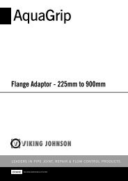
<strong>AquaGrip</strong> <strong>Flange</strong> <strong>Adaptor</strong>1) Pipe End PreparationCut pipe end square, remove any reversion. If required chamfer outsideedge of pipe to aide assembly. Ensure pipe is free from any longitudinalscore marks.Fig. 1<strong>English</strong>NOTE: Pipes should be expanded to original size after RollDown orSwage-Line Operations. If pipe has been coiled, it may be necessaryto re-round prior to assembly.NOTE: If the <strong>AquaGrip</strong> is being installed on:-• PE pipes that use a sacrificial or peelable protection layer on the externalsurface of the pipe (e.g. ProFuse, SecuraLine pipe) then ensure this outerlayer is removed before installing the <strong>AquaGrip</strong> fitting.• PE pipes with a co extruded colour layer that is homogeneous with thepipe and is the correct outside diameter for the <strong>AquaGrip</strong>, these shouldnot have the colour layer removed prior to installation.Fig. 22) InstallationCheck that the SDR rating of the liner is compatible with that of the PE pipe– in the event they are not <strong>Viking</strong> <strong>Johnson</strong> supply support liners as spares.Insert the liner fully into pipe ends until shoulders butt against pipe ends.Mark the pipes 100mm back from the ends to assist step 3.Do not dismantle the <strong>Adaptor</strong>. Back all nuts off one or two turnsand slide the <strong>Flange</strong> <strong>Adaptor</strong> completely over pipe end.3) Centralise FittingAlign flanges, fit flange gasket and tighten flange connecting bolts (A) fullyin accordance with standard flange techniques. Using mark from (2) ensurethere is sufficient pipe entry adjusting as necessary to achieve the settinggap as noted in Fig.4.4) Final AssemblyWorking round the fitting evenly tighten diametrically opposed nuts (i.e. 1&2,3&4), turning each one or two turns at a time. Continue working round untilcorrect bolt torque as noted below is achieved on ALL nuts, verifying thiswith a calibrated torque wrench, which must “break” without turning the nut.BOLTS DETAILSBolt Size M12Spanner Size 19mm A/FBolt Torque 55 to 65Nm.Fig. 3Fig. 4Fig. 510mm Setting Gap20mm Max GapINSTALLATION INSTRUCTIONSREV0346-48 Wilbury WayHitchin,HertfordshireSG4 0UD. UKTelephone: +44 (0)1462 443322Fax: +44 (0)1462 443311email: info@vikingjohnson.comwww.vikingjohnson.comThe Company reserves the right to amend any product without notice.DR6115_12_2011www.cranebsu.com