Test Transmitter / Signal Strength Indicator XPTT / XPTR
Test Transmitter / Signal Strength Indicator XPTT / XPTR
Test Transmitter / Signal Strength Indicator XPTT / XPTR
- No tags were found...

You also want an ePaper? Increase the reach of your titles
YUMPU automatically turns print PDFs into web optimized ePapers that Google loves.
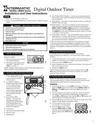
<strong>Test</strong> <strong>Transmitter</strong> / <strong>Signal</strong> <strong>Strength</strong> <strong>Indicator</strong> <strong>XPTT</strong> / <strong>XPTR</strong><strong>XPTT</strong>FlashingLEDLiving RoomBed Room<strong>XPTR</strong>HighRangePower Wiresin HomeLowRangeTypical <strong>Test</strong> Scenario<strong>Transmitter</strong>Sends Continuous"P1"ON/OFF CommandReceiverReceives and DisplaysContinuous "P1"ON/OFF CommandDescription:These devices provide help to installers to test the X10 <strong>Signal</strong> Integrity of any X10 System for optimum performance and reliability.1. <strong>XPTT</strong>: Sends a continuous "P1" Addressed ON/OFF X10 Command <strong>Signal</strong> transmission from the location where it is plugged in.2. <strong>XPTR</strong>: Measures the strength of X10 Command <strong>Signal</strong>s traveling throughout the home via the power wires.These devices simply plug-in and are recommended for testing all X10 PRO installations.Specific Requirements: 120VAC.Optional / Supplementary Devices & Modules:XPPF Plug-in Filter, XPF Wire-in Filter, XPNR Wire-in Noise Reducer, XPCP Passive Phase Coupler, XPCR Phase Coupler/Repeater.X10 Protocol:House Code Dial - Letters A-P, Default "A" Unit Number Dial - Numbers 1-16, Default "1"Each X10 Receiver Module is set to a unique Unit Number or to an identical Unit Number as desired.Each X10 Controller operating a specific set of Receiver Modules must be set to the same House Code as the Receivers they are controlling.Electrical Protocol:Nearly all residential homes are wired SPLIT-PHASE. Each 120V Phase is NOT directly connected with the other 120V phase. If an X10 Receiverdoes not respond to a Remote Controller, then check to ensure that the breaker serving the X10 Receiver is on the same phase as the Controller.If not, the breaker can be changed to the opposite phase. An alternative solution is recommended, to install a Phase Coupler for improving remo tecommunications throughout the home. See www.x10pro.com, then select Technical Support and PLC Troubleshooting.Installation:Note: For test purposes, you may want to change the address of any installed X10 Receiver Module that may be set up with the address "P1 " (toprevent cycling caused by the <strong>XPTT</strong>). Conversely, you may set an X10 Receiver Module to "P1" and watch for it to respond, once Noise iseliminated.1) At the proposed or installed <strong>Transmitter</strong>/Controller location:a) Plug the <strong>XPTT</strong> power cord into a 120VAC outlet, orb) Using insulated test probes, alligator clips or a 120VAC receptacle pigtail, connect the <strong>XPTT</strong> power cord to120VAC.2) Once plugged in, the <strong>XPTT</strong> will transmit ON/OFF Codes continuously at the "P1" X10 Address. The flashing LED indicates command signals arebeing transmitted. Leave the <strong>Test</strong> <strong>Transmitter</strong> at this location and go to 3).3) <strong>Test</strong> the <strong>Signal</strong> <strong>Strength</strong>:a) Plug-in the <strong>XPTR</strong> then push and hold the reset button. 25MV LED illuminates showing you have power. Release the Reset Button.The Low Range <strong>Signal</strong> <strong>Strength</strong> is read from the white colored numbers.The High Range <strong>Signal</strong> <strong>Strength</strong> is read from the yellow colored numbers, while pressing and holding the High Range Button.Note: The minimum signal strength required for X10 Receiver Module operation is 100mV. however, attempt to get as high a <strong>Signal</strong> in the HighRange as possible. Do this by systematically pulling plugs on electronic devices that could be generating noise. This may also require shutting offbreakers one at a time while you view the <strong>Signal</strong> <strong>Strength</strong> <strong>Indicator</strong> for <strong>Signal</strong> improvements.4) If the ERROR LED flashes, there is excessive Noise or false/incorrect electronic signals on the transmission line power wires that is causing theX10 <strong>Signal</strong> to become un-intelligible. The source of this Noise or unwanted signal should be identified and corrected to prevent interference withX10 operation.See Page 2 for detailed troubleshooting information.Tampa, FL 33542<strong>XPTT</strong>_<strong>XPTR</strong>_03_03/07Technical Support: (800) 832-4003