Jøtul F 370 Series
Jøtul F 370 Series Jøtul F 370 Series
English Table of contents Installation manual with technical data 1.0 Relationship to the authorities.................. 22 2.0 Technical data ............................................ 22 3.0 Installation ................................................. 23 4.0 Service.........................................................26 5.0 Optional Equipment ..................................26 Figures................................................................... 58 Table of contents General use and maintenance manual 6.0 Safety precautions 7.0 Choice of fuel 8.0 Use 9.0 Maintenance 10.0 Operational problems - troubleshooting 1.0 Relationship to the authorities Installation of a fireplace must be according to local codes and regulations in each country. All local regulations, including those which refer to national and European standards, must be observed when installing the product. Both an installation manual with technical data and a manual on general use and maintenance are enclosed with the product. The installation can only be used after it has been inspected by a qualified inspector. A product data plate of heat-resistant material is affixed to the product. This contains information about identification and documentation for the product. 2.0 Technical data Material: Finish: Fuel: Log length, max.: Operating range: Flue outlet: Flue pipe dimension: Cast iron Black or grey varnish Wood 30 cm 3.5-7,0 kW Top, rear Ø150 mm/min. 177 cm 2 cross section Approx. weight: - with cast-iron base: Approx. 163 kg - with concrete base: Approx. 194 kg - with cast-iron pedestal: Approx. 156 kg - with cast-iron leg: Approx. 154 kg - with cast-iron base and glass door: Optional extras: Dimensions, distances: See fig. 1 Approx. 165 kg Decoration plates fairy tale/ reed/cover for side windows, rotating set (Jøtul 373), glass decoration - top/sides/front, soap stone - top. Wood store. Product: Jøtul Room heater fired by solid fuel Standard Minimum distance to adjacent combustible materials: Minimum distance to adjacent combustible materials: Emission of CO in combustion products Flue gas temperature Nominal heat output Efficiency Operation range Fuel type Operational type The appliance can be used in a shared flue. Country Norway Sweden EUR Certificate/ standard Follow user`s instructions. Use only recommended fuels. Montage- und Bedienungsanleitung beachten. Verwenden Sie nur empfohlenen Brennstoffen. Respectez les consignes d'utilisation. Utilisez uniquement les combustibles recommandés. Serial no: Y-xxxx, Year: 200x Manufacturer: Jøtul AS POB 1441 Classification Klasse II OGC Intermittent N-1602 Fredrikstad Norway SP EN Approved by SP Sveriges Provnings- och Forskningsinstitut AB SP Swedish National Testing and Research Institute : : : : : : : : 221546 On all our products there is a label indicating the serial number and year. Write this number in the place indicated in the installation instructions. Always quote this serial number when contacting your retailer or Jøtul. Serial no. Technical data according to EN 13240 Nominal heat output: 5,5 kW Flue gas mass flow: 5,9 g/s Recommended chimney draught: 12 Pa Efficiency: 73%@5,8 kW CO emission (13% O 2 ): 0.12% Flue gas temperature: 330 o C Operational type: Intermittent Intermittent combustion in this context means normal use of the fireplace, i.e. fuel is added as soon as the fuel has burnt down to a suitable amount of embers. 22
Wood consumption Jøtul F 370 has a nominal heat output of 5,5 kW. Use of wood, with nominal heat emission: Approx. 1,9 kg/h. Another important factor for proper fuel consumption is that the logs are the correct size. The size of the logs should be: Kindling: Length: 30 cm Diameter: 2-5 cm Amount per fire: 6-8 pieces Firewood (split logs): Length: Ca 20 - 30 cm Diameter: Approx. 8 cm Intervals for adding wood: Approximately every 45 minutes Size of the fire: 1.4 kg Amount per load: 2 pieces Nominal heat emission is achieved when the air vent (fig. 23 A) is open approximately 100% and the handle for the ignition vent pulled out approximately 1-2 cm (fig. 23 B). 2.1 Floor Foundations It must be ensured that the foundations are dimensioned for the fireplace. Cf. «2.0 Technical data» for specification of weight. It is recommended that flooring which is not fastened to the foundations – so-called floating flooring – is removed during installation. Combustible floor protection Jøtul F 370 Series (except from Jøtul F 374) has a heat shield underneath which protects the base from radiation. The product has an integrated floor protection and may therefore be placed directly on a wooden floor. Any flooring made of combustible material, such as linoleum, carpets, etc. must be removed from under the floor plate Requirement for protecting combustible flooring in front of fireplace (see fig. 2) The front plate must be in accordance with national laws and regulations. Contact your local building authority regarding restrictions and installation requirements. 2.2 Walls Distance from the wall of flammable material – cf. fig. 1 The fireplace is authorised for use with an uninsulated flue with the distances to the wall of flammable material as shown in fig 1. 2.3 Ceiling There must be a minimum distance of 1000 mm to a combustible ceiling above the fireplace. 3.0 Installation English N.B. Check that the fireplace is free of any damage prior to commencing installation. The product is heavy! Make sure you have assistance when erecting and installing the fireplace. 3.1 Prior to installation 1. Standard product supplied in two packages. One with the fireplace itself and one with optional base in cast-iron/ concrete or pedestal in cast-iron. 2. When the product is unpacked, the burn plates, baffle plate, exhaust deflector, base plate, ash pan and riddling grate are removed. Also remove the small side burn plates and gasket for flue pipe which are in the ash pan. 3. Lift off the top plate with the top grid (fig. 18A) and bowl (fig. 18B). 4. Check that the operating handles work. 5. If the rear flue pipe outlet is used, first drill holes (fig. 6A) in the cut-out covers for the flue pipe before they are knocked out with the aid of e.g a ball-pane hammer. 6. Place the wooden block (fig. 6B) that holds the exhaust deflectors in position so that the side plates are supported when the cut-out covers are removed. 7. Spread out the cardboard packaging on the floor. Lay the stove carefully on its side. 8. If the glass décor set (optional extras) is to be used, the 4 recessed head screws on the bottom are removed (fig. 4B) with the aid of the key included with the glass décor set. Supply of external air With F 370 it is possible to draw external air directly into the product through the base/pedestal, or through a flexible supply hose from outside/chimney* and to the outlet of the product (fig. 4C). * This shall only apply if the chimney has its own duct for external air. 3.2 Assembly Jøtul F 371 - cast-iron base - (fig. 4, 6, 7 and 8) N.B. If the flexible hose is to be connected through a hole in the floor, the knock out covers are not knocked out/removed. 1. If flexible hose, 100 mm diameter, for external air supply is to be connected to the outlet under the burn chamber (fig. 4C), drill one hole (fig. 6A) in each cut-out cover at the lower part of the base and knock them out. N.B. Make sure the rear plate (fig. 7 A) in the base is positioned, when the cut-out cover is being knocked out. 2. Remove rack and rear plate in the base. Check that the handle 3. 4. 5. 6. 7. 8. in the external air vent (fig. 4D) is in the foremost position. Assemble the base with the burn chamber with the aid of the 4 screws (M8x30 mm) from the screws bag (fig. 4A). Get assistance and carefully lift the product up. Draw the flexible hose through the hole and fasten it to the outlet with the aid of a hose clip. N.B. Make sure that the hose is long enough to avoid any joints. The base area must be protected from heat radiation from the product with the aid of the accompanying heat shield (fig. 8A). Fasten this with the 2 screws from the screws bag as shown in fig. 8B. Adjust the product with the help of the 4 adjusting screws (fig. 8C). Reassemble the the rack and the rear plate in the base. 23
- Page 1 and 2: Jøtul F 370 Series Jøtul F 370 Se
- Page 3 and 4: Norsk Forbruk av ved Jøtul F 370 h
- Page 5 and 6: Norsk • Før det tas hull i skors
- Page 7 and 8: Indhold Innstallationsmanual med te
- Page 9 and 10: Dansk Jøtul F 372 - Betonsokkel (f
- Page 11 and 12: 4.0 Service 5.0 Ekstraudstyr Dansk
- Page 13 and 14: Förbrukning av ved Jøtul F 370 ha
- Page 15 and 16: Svenska • Eldstaden bör provmont
- Page 17 and 18: Sisällysluettelo Asennusohjeet ja
- Page 19 and 20: Suomi Jøtul F 372 - Betonisokkeli
- Page 21: 4.0 Huolto Varoitus! Tuotteeseen ei
- Page 25 and 26: English • Several solid fuel fire
- Page 27 and 28: Sommaire Manuel d’installation et
- Page 29 and 30: francais Jøtul F 372 - La base en
- Page 31 and 32: 3.7 Utilisation (fig. 23) • Ouvri
- Page 33 and 34: Indice Manual de instalación con i
- Page 35 and 36: Español 6. El área de la base deb
- Page 37 and 38: 3. Asegúrese de que la bandeja par
- Page 39 and 40: Indice generale Manuale di installa
- Page 41 and 42: italiano Jøtul F 372 - La base in
- Page 43 and 44: 3.7 Utilizzo della stufa (fig. 23)
- Page 45 and 46: Inhalt Aufstellungshandbuch mit tec
- Page 47 and 48: DEUTSCH 6. 7. 8. Hinweis: Stellen S
- Page 49 and 50: 3.5 Überprüfen der Funktionen (Ab
- Page 51 and 52: Inhoudsopgave Installatiehandleidin
- Page 53 and 54: NEDERLANDS Jøtul F 372 - Betonsten
- Page 55 and 56: • Zorg ervoor dat het vuur geleid
- Page 62 and 63: Fig. 1 c Fig. 2a Fig. 2b Norge 62
- Page 64 and 65: Fig. 7 Fig. 8 B A A C C C C Fig.9 F
- Page 66 and 67: Fig.13 A A Fig.14 Fig.15 A A 66
- Page 68 and 69: Fig.20 A Fig.21 A Fig.22 Fig.23 G H
- Page 71 and 72: Sluttkontroll av ildsteder Quality
English<br />
Table of contents<br />
Installation manual with technical data<br />
1.0 Relationship to the authorities.................. 22<br />
2.0 Technical data ............................................ 22<br />
3.0 Installation ................................................. 23<br />
4.0 Service.........................................................26<br />
5.0 Optional Equipment ..................................26<br />
Figures................................................................... 58<br />
Table of contents<br />
General use and maintenance manual<br />
6.0 Safety precautions<br />
7.0 Choice of fuel<br />
8.0 Use<br />
9.0 Maintenance<br />
10.0 Operational problems - troubleshooting<br />
1.0 Relationship to the<br />
authorities<br />
Installation of a fireplace must be according to local codes and<br />
regulations in each country.<br />
All local regulations, including those which refer to national<br />
and European standards, must be observed when installing the<br />
product.<br />
Both an installation manual with technical data and a manual<br />
on general use and maintenance are enclosed with the product.<br />
The installation can only be used after it has been inspected by<br />
a qualified inspector.<br />
A product data plate of heat-resistant material is affixed to the<br />
product. This contains information about identification and<br />
documentation for the product.<br />
2.0 Technical data<br />
Material:<br />
Finish:<br />
Fuel:<br />
Log length, max.:<br />
Operating range:<br />
Flue outlet:<br />
Flue pipe dimension:<br />
Cast iron<br />
Black or grey varnish<br />
Wood<br />
30 cm<br />
3.5-7,0 kW<br />
Top, rear<br />
Ø150 mm/min. 177 cm 2 cross<br />
section<br />
Approx. weight:<br />
- with cast-iron base: Approx. 163 kg<br />
- with concrete base: Approx. 194 kg<br />
- with cast-iron pedestal: Approx. 156 kg<br />
- with cast-iron leg: Approx. 154 kg<br />
- with cast-iron base<br />
and glass door:<br />
Optional extras:<br />
Dimensions, distances: See fig. 1<br />
Approx. 165 kg<br />
Decoration plates fairy tale/<br />
reed/cover for side windows,<br />
rotating set (Jøtul 373), glass<br />
decoration - top/sides/front,<br />
soap stone - top.<br />
Wood store.<br />
Product:<br />
Jøtul<br />
Room heater fired by solid fuel<br />
Standard<br />
Minimum distance to adjacent combustible materials:<br />
Minimum distance to adjacent combustible materials:<br />
Emission of CO in combustion products<br />
Flue gas temperature<br />
Nominal heat output<br />
Efficiency<br />
Operation range<br />
Fuel type<br />
Operational type<br />
The appliance can be used in a shared flue.<br />
Country<br />
Norway<br />
Sweden<br />
EUR<br />
Certificate/<br />
standard<br />
Follow user`s instructions. Use only recommended fuels.<br />
Montage- und Bedienungsanleitung beachten.<br />
Verwenden Sie nur empfohlenen Brennstoffen.<br />
Respectez les consignes d'utilisation. Utilisez uniquement<br />
les combustibles recommandés.<br />
Serial no: Y-xxxx, Year: 200x<br />
Manufacturer:<br />
Jøtul AS<br />
POB 1441<br />
Classification<br />
Klasse II<br />
OGC<br />
Intermittent<br />
N-1602 Fredrikstad<br />
Norway<br />
SP<br />
EN<br />
Approved by<br />
SP Sveriges Provnings- och<br />
Forskningsinstitut AB<br />
SP Swedish National<br />
Testing and Research<br />
Institute<br />
:<br />
:<br />
:<br />
:<br />
:<br />
:<br />
:<br />
:<br />
221546<br />
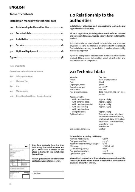
On all our products there is a label<br />
indicating the serial number and<br />
year. Write this number in the<br />
place indicated in the installation<br />
instructions.<br />
Always quote this serial number when<br />
contacting your retailer or Jøtul.<br />
Serial no.<br />
Technical data according to EN 13240<br />
Nominal heat output:<br />
5,5 kW<br />
Flue gas mass flow:<br />
5,9 g/s<br />
Recommended chimney draught: 12 Pa<br />
Efficiency:<br />
73%@5,8 kW<br />
CO emission (13% O 2<br />
): 0.12%<br />
Flue gas temperature:<br />
330 o C<br />
Operational type:<br />
Intermittent<br />
Intermittent combustion in this context means normal use of the<br />
fireplace, i.e. fuel is added as soon as the fuel has burnt down to<br />
a suitable amount of embers.<br />
22


