rotationslaser dw077 - Service - DeWALT
rotationslaser dw077 - Service - DeWALT
rotationslaser dw077 - Service - DeWALT

You also want an ePaper? Increase the reach of your titles
YUMPU automatically turns print PDFs into web optimized ePapers that Google loves.
– Hold the tool at the desired position against the<br />
wall and mark the location of the two mounting<br />
holes on the wall (fig. D4).<br />
– Drill a hole at each of the marked locations<br />
(required: ø 6 mm, approx. 35 mm deep).<br />
– Insert a corresponding plug into each of the<br />
holes.<br />
– Turn a screw into each of the plugs<br />
(required: 6 x 50 mm).<br />
– Hang the tool on the screws.<br />
• Adjust the leveling knob (3) to stabilise the tool<br />
when necessary.<br />
• Adjust the tool for a level application.<br />
Tripod set-up (fig. D5)<br />
The tool has been equipped with a tripod receptacle<br />
for mounting to the DE0735/DE0736 tripod<br />
(optional) or any other tripod with the required<br />
ratings stated in the technical data.<br />
• Place the tripod (28) on a relatively smooth and<br />
level surface.<br />
• Mount the tool to the tripod by turning the threaded<br />
pin (29) into the receptacle (30) in the base.<br />
• Adjust the tool for a level or plumb application.<br />
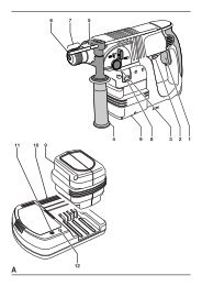
Adjusting the tool (fig. A, E1 & E2)<br />
The tool can be adjusted for both level (fig. E1) and<br />
plumb (fig. E2) applications.<br />
Self-leveling feature (fig. A)<br />
• To initiate the leveling procedure, switch on the<br />
tool. The leveling procedure is indicated by the<br />
flashing of the leveling indicators (16 & 17) and<br />
the laser beam. Once the tool has found its level<br />
position the leveling indicators and the laser<br />
beam will stop flashing and remain on.<br />
• The leveling indicators and the laser beam<br />
repeatedly flash three times rapidly to indicate<br />
that the tool has been set up at a slope that is<br />
beyond the self-leveling range of 5°. Switch the<br />
tool off, re-adjust the tool set-up within the selfleveling<br />
range and switch the tool on again.<br />
Level adjustment (fig. E1)<br />
• Place the tool into the required position as shown.<br />
• Switch on the tool to initiate the leveling<br />
procedure.<br />
ENGLISH<br />
Plumb adjustment (fig. E2)<br />
• Place the tool into the required position as shown.<br />
• Switch on the tool to initiate the leveling procedure.<br />
As the leveling procedure for plumb applications<br />
only requires adjustment of the Y axis, only the<br />
corresponding leveling indicator (17) will be<br />
operational.<br />
Manually adjusting the level position (fig. A)<br />
By using the remote control the tool can be adjusted<br />
manually. The manual adjustment mode is<br />
particularly useful in applications with slope angles in<br />
both X and Y-axis.<br />
• To activate the manual adjustment mode press<br />
the key (22). The leveling indicators (16 & 17) go off.<br />
• Use the keys (20) to adjust the tool in the X-axis.<br />
• Use the keys (21) to adjust the tool in the Y-axis.<br />
• To discontinue the manual adjustment mode,<br />
press the key (22) again.<br />
After discontinuing the manual leveling<br />
mode the self-leveling feature automatically<br />
takes over and re-adjusts the tool to level<br />
position. The manual adjustments will be<br />
lost immediately!<br />
Aligning the laser line (fig. A & F1 - F5)<br />
Level alignment<br />
• With the tool switched on and the laser head<br />
rotating, align the laser line with the position mark.<br />
• If adjustment is required, proceed as follows:<br />
With tool in floor set-up (fig. F1):<br />
• The tool can be placed on any sturdy object to<br />
obtain the required height.<br />
With tool in wall set-up (fig. F2):<br />
• Loosen the locking knob (12) and adjust the rack<br />
pinion wheel (9) to set the tool to the correct<br />
position. Tighten the locking knob (12).<br />
With tool in tripod set-up (fig. F3):<br />
• Adjust the tripod to set the tool to the required<br />
height.<br />
Plumb alignment (fig. A, F4 & F5)<br />
• With the tool switched on and the laser head<br />
rotating, align the laser line with the position mark.<br />
• If adjustment is required, proceed as follows:<br />
43