Instruction manual BPT260S-BPT310S-BPT410S - Luna Norge AS
Instruction manual BPT260S-BPT310S-BPT410S - Luna Norge AS
Instruction manual BPT260S-BPT310S-BPT410S - Luna Norge AS

Create successful ePaper yourself
Turn your PDF publications into a flip-book with our unique Google optimized e-Paper software.
Operating position 2:<br />
Idling ...................................................................LpA 84,4 dB (A)<br />
Operating.............................................................LpA 95,7 dB (A)<br />
The specified values are emission levels and are not necessarily to be seen<br />
as safe operating levels. Although there is a correlation between emission<br />
and imission levels, these do not constitute a basis for determining the necessity<br />
of additional safety measures. Workplace conditions which could<br />
influence the noise imission level include the duration of resonance, spatial<br />
particulars, other noise sources etc. For example, the number of machines<br />
and other work being performed. The permissible workplace levels<br />
can vary from country to country. This information is intended to allow<br />
the user to make a better estimation of the hazards and risks involved.<br />
3.3 Dust emission<br />
The planer thicknesser has been dust emission inspected.<br />
BPT-260S, BPT-310S:<br />
At an air velocity of 20 m/s on the dust port dia 100mm:<br />
Vacuum pressure 900 Pa<br />
Volume flow 565 m³/h<br />
BPT-410S:<br />
At an air velocity of 20 m/s on the dust port dia 120mm:<br />
Vacuum pressure 950 Pa<br />
Volume flow 810 m³/h<br />
The machine meets a workplace dust emission limit of 2 mg/m³.<br />
3.4 Content of delivery<br />
Planer thicknesser assembly<br />
Jointer fence assembly.<br />
Cutter block guard<br />
Knife setting gauge<br />
Operating tools<br />
Operating <strong>manual</strong><br />
Spare parts list<br />
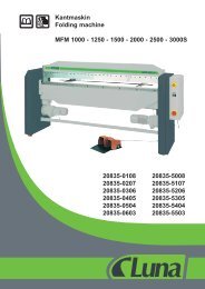
3.5 Machine description<br />
A Outfeed table<br />
B Jointer fence<br />
C ON/OFF switch<br />
D Cutterblock guard<br />
E Table tilt handle<br />
F Table adjustment lock<br />
G Table adjustment handle<br />
H Infeed table<br />
I Table-cabinet lock<br />
J Mains plug<br />
Fig. 1<br />
Fig. 2<br />
24<br />
K Thickness table<br />
L Power feed ON/OFF handle<br />
M Thickness table lock<br />
(BPT-310S, BPT-410S)<br />
N Thickness table adjust<br />
handwheel<br />
O Dust hood<br />
P Dust hood disengagement<br />
knob<br />
4. TRANSPORT AND START UP<br />
4.1 Transport and installation<br />
For transport use a forklift or hand trolley. Make sure the machine does<br />
not tip or fall off during transport. Remove the carriage blots and slide the<br />
machine carefully off the pallet.<br />
ATTENTION: The planer tables are precisely aligned ex. works. They<br />
may only be loaded when they are closed and the tablecabinet locks (I, Fig<br />
1) are engaged, otherwise they may be damaged. The machine is designed<br />
to operate in closed rooms and must be placed stable on firm and levelled<br />
ground. The machine can be bolted down if required.<br />
4.2 Assembly<br />
If you notice any transport damage while unpacking, notify your supplier<br />
immediately. Do not operate the machine! Dispose of the packing in an<br />
environmentally friendly manner. Clean all rust protected surfaces with a<br />
mild solvent. Mount the table cutterblock guard (D, Fig 1).<br />
Note: The maximum clearance between cutter block guard and table may<br />
not be more than 75mm<br />
4.3 Mains connection<br />
Mains connection and any extension cords used must comply with applicable<br />
regulations. The mains voltage must comply with the information on<br />
the machine licence plate. The mains connection must have a 16A surgeproof<br />
fuse. Only use connection cables marked H07RN-F.<br />
Connections and repairs to the electrical equipment may only be carried<br />
out by qualified electricians.<br />
ATTENTION:<br />
- Check first if the cutter block runs freely and if all safety devices are fitted<br />
before starting the machine.<br />
- If the direction of rotation is not correct, the phase converter inside the<br />
CCE Euro plug must be pushed in and turned 180°. (See rotation arrow on<br />
machine for correct rotation)<br />
4.4 Dust connection<br />
Before initial operation, the machine must be connected to a dust extractor.<br />
The suction should switch on automatically when the jointer is switched<br />
on. The flow rate on the suction port must be 20m/sec. Flexible hoses<br />
must be of nonflammable quality, and must be connected to the machine<br />
ground system.<br />
4.5 Starting operation<br />
You can start the machine with the green on button. The red button on the<br />
main switch stops the machine. The power feed can be engaged and disengaged<br />
with handle (L, Fig 2). In case of machine overload the motor overload<br />
cut-off will react. After appr.10 min of cooling the machine can be<br />
started again.<br />
5. MACHINE OPERATION<br />
Change of operating mode (planing to thicknessing and back) may only<br />
be performed when the machine is at a complete standstill.<br />
5.1 Jointing and planing<br />
Correct operating position:<br />
Position yourselves offset to the infeed table (Fig 4).<br />
Fig. 4<br />
Work piece handling:<br />
Feed the work piece straight across the infeed table, holding your fingers<br />
close together, guiding the work piece with the palm of your hands. Never<br />
put your hands under the cutter block cover. Always keep your hands well<br />
clear of the cutter block Do not pull the work piece back over the unguarded<br />
cutter block Always plane the work piece over its entire length. Adjust<br />
depth of cut with lever (G). Loosen clamping knob (F) for adjustment.