Jøtul F 370 Series
Jøtul F 370 Series
Jøtul F 370 Series
You also want an ePaper? Increase the reach of your titles
YUMPU automatically turns print PDFs into web optimized ePapers that Google loves.
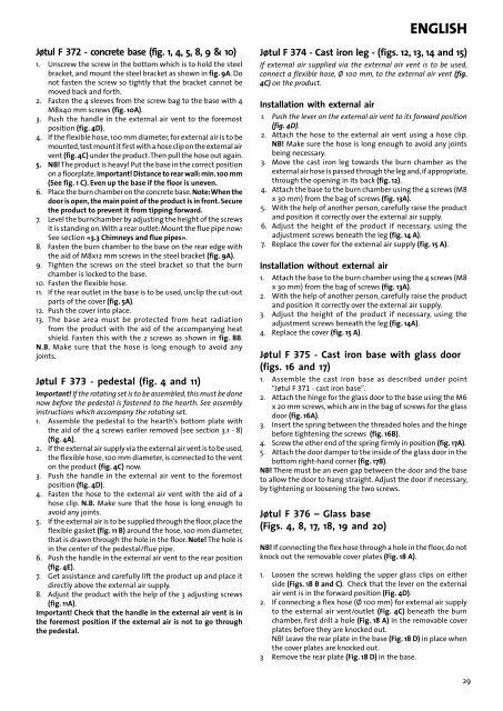
<strong>Jøtul</strong> F 372 - concrete base (fig. 1, 4, 5, 8, 9 & 10)<br />
1. Unscrew the screw in the bottom which is to hold the steel<br />
bracket, and mount the steel bracket as shown in fig. 9A. Do<br />
not fasten the screw so tightly that the bracket cannot be<br />
moved back and forth.<br />
2. Fasten the 4 sleeves from the screw bag to the base with 4<br />
M8x40 mm screws (fig. 10A).<br />
3. Push the handle in the external air vent to the foremost<br />
position (fig. 4D).<br />
4. If the flexible hose, 100 mm diameter, for external air is to be<br />
mounted, test mount it first with a hose clip on the external air<br />
vent (fig. 4C) under the product. Then pull the hose out again.<br />
5. NB! The product is heavy! Put the base in the correct position<br />
on a floorplate. Important! Distance to rear wall: min. 100 mm<br />
(See fig. 1 C). Even up the base if the floor is uneven.<br />
6. Place the burn chamber on the concrete base. Note: When the<br />
door is open, the main point of the product is in front. Secure<br />
the product to prevent it from tipping forward.<br />
7. Level the burnchamber by adjusting the height of the screws<br />
it is standing on. With a rear outlet: Mount the flue pipe now:<br />
See section «3.3 Chimneys and flue pipes».<br />
8. Fasten the burn chamber to the base on the rear edge with<br />
the aid of M8x12 mm screws in the steel bracket (fig. 9A).<br />
9. Tighten the screws on the steel bracket so that the burn<br />
chamber is locked to the base.<br />
10. Fasten the flexible hose.<br />
11. If the rear outlet in the base is to be used, unclip the cut-out<br />
parts of the cover (fig. 5A).<br />
12. Push the cover into place.<br />
13. The base area must be protected from heat radiation<br />
from the product with the aid of the accompanying heat<br />
shield. Fasten this with the 2 screws as shown in fig. 8B.<br />
N.B. Make sure that the hose is long enough to avoid any<br />
joints.<br />
<strong>Jøtul</strong> F 373 - pedestal (fig. 4 and 11)<br />
Important! If the rotating set is to be assembled, this must be done<br />
now before the pedestal is fastened to the hearth. See assembly<br />
instructions which accompany the rotating set.<br />
1. Assemble the pedestal to the hearth’s bottom plate with<br />
the aid of the 4 screws earlier removed (see section 3.1 - 8)<br />
(fig. 4A).<br />
2. If the external air supply via the external air vent is to be used,<br />
the flexible hose, 100 mm diameter, is connected to the vent<br />
on the product (fig. 4C) now.<br />
3. Push the handle in the external air vent to the foremost<br />
position (fig. 4D).<br />
4. Fasten the hose to the external air vent with the aid of a<br />
hose clip. N.B. Make sure that the hose is long enough to<br />
avoid any joints.<br />
5. If the external air is to be supplied through the floor, place the<br />
flexible gasket (fig. 11 B) around the hose, 100 mm diameter,<br />
that is drawn through the hole in the floor. Note! The hole is<br />
in the center of the pedestal/flue pipe.<br />
6. Push the handle in the external air vent to the rear position<br />
(fig. 4E).<br />
7. Get assistance and carefully lift the product up and place it<br />
directly above the external air supply.<br />
8. Adjust the product with the help of the 3 adjusting screws<br />
(fig. 11A).<br />
Important! Check that the handle in the external air vent is in<br />
the foremost position if the external air is not to go through<br />
the pedestal.<br />
eNglish<br />
<strong>Jøtul</strong> F 374 - Cast iron leg - (figs. 12, 13, 14 and 15)<br />
If external air supplied via the external air vent is to be used,<br />
connect a flexible hose, Ø 100 mm, to the external air vent (fig.<br />
4C) on the product.<br />
Installation with external air<br />
1. Push the lever on the external air vent to its forward position<br />
(fig. 4D).<br />
2. Attach the hose to the external air vent using a hose clip.<br />
NB! Make sure the hose is long enough to avoid any joints<br />
being necessary.<br />
3. Move the cast iron leg towards the burn chamber as the<br />
external air hose is passed through the leg and, if appropriate,<br />
through the opening in its back (fig. 12).<br />
4. Attach the base to the burn chamber using the 4 screws (M8<br />
x 30 mm) from the bag of screws (fig. 13A).<br />
5. With the help of another person, carefully raise the product<br />
and position it correctly over the external air supply.<br />
6. Adjust the height of the product if necessary, using the<br />
adjustment screws beneath the leg (fig. 14 A).<br />
7. Replace the cover for the external air supply (fig. 15 A).<br />
Installation without external air<br />
1. Attach the base to the burn chamber using the 4 screws (M8<br />
x 30 mm) from the bag of screws (fig. 13A).<br />
2. With the help of another person, carefully raise the product<br />
and position it correctly over the external air supply.<br />
3. Adjust the height of the product if necessary, using the<br />
adjustment screws beneath the leg (fig. 14A).<br />
4. Replace the cover (fig. 15 A).<br />
<strong>Jøtul</strong> F 375 - Cast iron base with glass door<br />
(figs. 16 and 17)<br />
1. Assemble the cast iron base as described under point<br />
“<strong>Jøtul</strong> F 371 - cast iron base”.<br />
2. Attach the hinge for the glass door to the base using the M6<br />
x 20 mm screws, which are in the bag of screws for the glass<br />
door (fig. 16A).<br />
3. Insert the spring between the threaded holes and the hinge<br />
before tightening the screws (fig. 16B).<br />
4. Screw the other end of the spring firmly in position (fig. 17A).<br />
5. Attach the door damper to the inside of the glass door in the<br />
bottom right-hand corner (fig. 17B).<br />
NB! There must be an even gap between the door and the base<br />
to allow the door to hang straight. Adjust the door if necessary,<br />
by tightening or loosening the two screws.<br />
<strong>Jøtul</strong> F 376 – Glass base<br />
(Figs. 4, 8, 17, 18, 19 and 20)<br />
NB! If connecting the flex hose through a hole in the floor, do not<br />
knock out the removable cover plates (Fig. 18 A).<br />
1. Loosen the screws holding the upper glass clips on either<br />
side (Figs. 18 B and C). Check that the lever on the external<br />
air vent is in the forward position (Fig. 4D).<br />
2. If connecting a flex hose (Ø 100 mm) for external air supply<br />
to the external air vent/outlet (Fig. 4C) beneath the burn<br />
chamber, first drill a hole (Fig. 18 A) in the removable cover<br />
plates before they are knocked out.<br />
NB! Leave the rear plate in the base (Fig. 18 D) in place when<br />
the cover plates are knocked out.<br />
3 Remove the rear plate (Fig. 18 D) in the base.<br />
29


