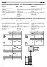
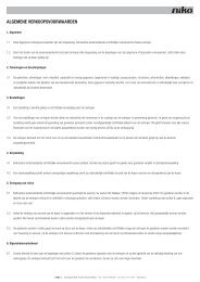
65-412/65-413/65-416/65-417 R,L,C Function of the 'DALI' LED: 16A - DALI CONTROL 65-417 Green LED: voltage is present on the bus, no error detection 100 ... 3680W DALI Blinking green LED: voltage OK and data present on the bus 100 ... 3680VA 100 ... 3680VA Red LED: bus overload (over 250 mA): too many ECG and/or control systems connected. See also diagrams delivered with <strong>Niko</strong> DALI components. Example: 16A dimmer: 16A x 230V~ x 0,952 (cos phi2) = 3312 VA maximum load. Pdim/Ptrafo % cos j vollast 65% 70% 75% 80% 85% 90% 95% 100% Psec (max.) = Ptrafo (max.) * x % 0,83 51% 0,90 55% 0,91 53% 59% 0,92 51% 57% 62% 0,93 50% 55% 60% 65% 0,94 53% 58% 63% 68% 0,95 51% 56% 61% 66% 70% 0,96 50% 54% 59% 64% 68% 73% 0,97 53% 57% 62% 66% 70% 75% 0,98 51% 55% 60% 64% 68% 72% 77% 0,99 54% 58% 62% 66% 70% 74% 78% 1 52% 56% 60% 64% 68% 72% 76% 80% Use of the table by means of an example: Given: Pdim (max.) = 1000VA Ptrafo (max.) = 1200VA cosj = 0,95 Required: Psec (max.)? Solution: Pdim (max.) / Ptrafo (max.) = 1000 / 1200 = 83,3% (±85%) and the cosj = 0,95. Based on this table, these 2 figures give us the value 56%. Psec (max.) = Ptrafo (max.) x 56% Psec (max.) = 1200VA x 56% = 672W 5. CAUTION DURING OPERATION - When using a transformer, make sure that the transformer is suitable for use with a dimmer. - During operation of the controller, the dimmer is never electrically isolated from the power grid. All parts therefore remain under voltage, even when the load (e.g. the light) is 'off'. - The dimmer is not suitable for controlling motors. - When using wirewound transformers (inductive load, symbol L), one must take into account the power factor of the transformers (expressed in 'cosinus phi'). Load the transformers fully, or at least to 80% of their nominal load. When calculating the dimmer’s total power consumption, take into account the efficiency of the transformer used (so-called 'power factor'). The total capacity of the connected transformers expressed in VA may not exceed the maximum capacity of the dimmer. For fully loaded transformers, the maximum load is approximately equal to the maximum capacity of the dimmer multiplied by the cosine phi squared. 6. TROUBLESHOOTING Overvoltage protection Overvoltage can occur due to an error in the load. The dimmer switches off and the red LED V lights. Take a note of the error code and restart the dimmer by briefly pressing the 'Select' push button. Overcurrent protection This is activated in case of a short-circuit, or if the current through the load exceeds the maximum allowed current by 10%. The dimmer switches off and the red LED A lights. Note down the error code and restart the dimmer by briefly pressing the 'Select' push button. Temperature protection If the temperature on the inside of the cooling extrusion exceeds 85°C, the dimmer will switch to protection mode. The dimmer switches off and the red LED C lights. Take a note of the error code and restart the dimmer, after cooling down, by briefly pressing the 'Select' push button. Additional for dimmers 65-413 and 65-417 (DALI control) DALI red LED lights: overload of the bus (over 250 mA): too many ECG and/or control systems connected. Solution: switch over all or some of the wall mounted circuit boards to an additional power supply. Error codes: 130 Mains voltage too low (253V~) 132 Overvoltage 133 Repeated overvoltage 134 Overload 135 Short-circuit 136 Temperature protection right cooling unit 137 Temperature protection left cooling unit 138 Dimmer load not connected 7. TECHNICAL DATA - Power supply voltage: ...............................230V~ ±10%; 50Hz - Stand-by power: .......................................50mA - Leakage current (to earth): .........................0,7mA per dimmer - Max. cable cross-section per terminal: ........4mm 2 or 2 x 2,5mm 2 - Max. output voltage: ..................................power supply voltage x 0,97 (dissipated power = max. 2,5% of the input power = max. 100W) - Max. temperature of the cover (Tc): ............85°C - Low voltage terminals - max. cable cross-section per terminal: .....2,5 mm 2 or 2 x 1,5mm 2 - Maximum short-circuit voltage: ...................electronically restricted to 80A - Non-replaceable fuses - Analog control wiring (65-412 & 65-416) - control circuit and power circuit of the dimmer are galvanically isolated - SELV for analog control - DALI control wiring (65-413 & 65-417) - SELV for supply of the DALI bus (DALI components have 2,5kV basic insulation only) - Cross-section of DALI bus cable: up to 100m: 0,5mm 2 up to 150m: 0,75mm 2 up to 300m: 1,50mm 2 - Wiring insulation = 2,5kV Type Max. load Max. switch-on current* 65-412 2760VA (12A) 80A Control signal Min. load 0/1/10V and N.O. contact nv <strong>Niko</strong> sa Industriepark West 40, BE-9100 Sint-Niklaas, Belgium — tel. +32 3 778 90 00 — fax +32 3 777 71 20 — e-mail: support@<strong>Niko</strong>.be — www.niko.be PM065-41X00R08171 100W 65-413 2760VA (12A) 80A DALI 100W 65-416 3680VA (16A) 80A 0/1/10V and N.O. contact 100W 65-417 3680VA (16A) 80A DALI 100W * exceeding the maximum switch-on current results in a slower switch-on of the dimmer. Load table at ambient temperature of 35°C 12A 2760W 3680W 2070W 2760W 1380W 1840W 690W 16A 920W a t Standards and regulations - Conforms to the European standard EN60669-2-1 - EMC emission EN55015 - DALI European standard EN60929 annex E Mechanical construction - Dimensions: H 303mm x W 200mm x D 100mm - Installation: in distribution enclosure - Weight: 4,5kg Environmental factors - Ambient temperature (Ta): 35°C - Operating temperature: see load table - Non-condensing atmospheric humidity 10 20 30 40 50 60 8. MAINTENANCE OF THE PRODUCT If the distribution enclosure is provided with a ventilation system including a filter, this will have to be cleaned regularly. Cooling extrusion and ventilation slots must be dust and dirtfree. 9. GUARANTEE PROVISIONS - Period of guarantee: 2 years from date of delivery. The delivery date is the invoice date of purchase of the product by the consumer. If there is no invoice, the date of production applies. - The consumer is obliged to inform <strong>Niko</strong> in writing about the defect, within two months after stating the defect. - In case of a failure to conform, the consumer has the right to a repair or replacement (decided by <strong>Niko</strong>) free of charge. - <strong>Niko</strong> cannot be held liable for a defect or damage as a result of an incorrect installation, improper or careless use or wrong usage or transformation of the goods. - The compulsory regulations of the national legislation concerning the sales of consumer goods and the protection of the consumers in the countries where <strong>Niko</strong> sells, directly or via sister or daughter companies, chain stores, distributors, agents or permanent sales representatives, take priority over the rules and regulations mentioned above. 10. DIAGRAMS S165412: 3 x 65-412 3 x 400V + N with 10 x N.O. push buttons (07-000) per dimmer S165416: 3 x 65-416 3 x 230V with 1 x 09-011 S265416: 2 x 65-416 with 05-350 S365416: 1 x 65-416 + 05-007 MAX. MIN. °C
65-412/65-413/65-416/65-417 R,L,C 30 X L1 3 x 400V~ + N L2 L3 N S165412 - + NIKO 09-011 1 V DC + L1 3 x 230V~ L2 L3 S165416 2 3 Com. + - 65-412 DIMMER R,L,C Max.12A 1 V DC + 4 N NL 2 3 Com. + - 4 65-416 DIMMER R,L,C ON PE N NL 30 X OFF 1 2 ON PE OFF 1 2 1 V DC + 2 3 Com. + - 65-412 DIMMER R,L,C Max.12A 1 V DC + 4 N NL 2 3 Com. + - 65-416 DIMMER R,L,C PE 4 1 2 3 4 N NL 30 X PE 65-416 DIMMER N NL nv <strong>Niko</strong> sa Industriepark West 40, BE-9100 Sint-Niklaas, Belgium — tel. +32 3 778 90 00 — fax +32 3 777 71 20 — e-mail: support@<strong>Niko</strong>.be — www.niko.be PM065-41X00R08171 V DC + + Com. - R,L,C Max.16A Max.16A Max.16A ON OFF 1 2 ON OFF 1 2 1 V DC + 2 3 Com. + - 65-412 DIMMER R,L,C Max.12A 4 N NL ON PE OFF 1 2 ON PE OFF 1 2