Manuel technique (pdf, 0.28 MB) - Niko
Manuel technique (pdf, 0.28 MB) - Niko
Manuel technique (pdf, 0.28 MB) - Niko

Create successful ePaper yourself
Turn your PDF publications into a flip-book with our unique Google optimized e-Paper software.
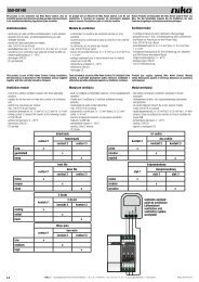
65-412/65-413/65-416/65-417 R,L,C<br />
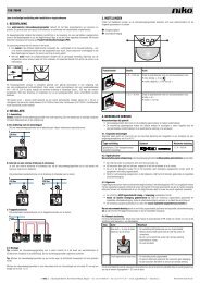
1. LEGAL WARNINGS<br />
- Read the complete manual before attempting installation and activating the system.<br />
- The installation has to be carried out by a registered installer and in compliance with the statutory regulations.<br />
- This user manual has to be handed over to the user. It has to be included in the electrical installation file and has to<br />
be passed on to any new owners. Additional copies are available on the <strong>Niko</strong> website or via the support service.<br />
- During installation, the following has to be taken into account (not limited to list below):<br />
- The statutory laws, standards and regulations;<br />
- The state of the art <strong>technique</strong> at the moment of installation;<br />
- This user manual, which must be read within the scope of each specific installation, only states general<br />
regulations;<br />
- The rules of proper workmanship<br />
- In case of questions, you can consult <strong>Niko</strong>’s support service or contact a registered control organisation.<br />
Support Belgium: Support UK:<br />
+32 3 778 90 80 +44 1525877707<br />
website : http://www.niko.be http://www.nikouk.com<br />
e-mail: support@niko.be sales@nikouk.com<br />
In case of a defect, you can return your product to a registered <strong>Niko</strong> wholesaler, together with a clear description<br />
of your complaint (Conditions of use, stated defect…).<br />
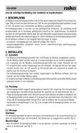
2. DESCRIPTION<br />
65-412; 12A, universal analog dimmer<br />
65-416; 16A, universal analog dimmer<br />
65-413; 12A, universal DALI dimmer<br />
65-417; 16A, universal DALI dimmer<br />
Universal dimmers, for the regulation of dimmable lighting sources only.<br />
The following types of loads are allowed, including all combinations:<br />
R: resistive loads – incandescent lamps and halogen 230V~<br />
L: inductive loads – ferromagnetic transformers<br />
C: capacitive loads – electronic transformers (no electronic ballasts – ECG)<br />
No adaptation to the type of load required. Two types are available; maximum load 12A or 16A. Each type has<br />
an overvoltage, overload, short-circuit and temperature protection with auto-reset and LED indication. Extensive<br />
help for users and installers. Display of voltage, current, temperature and status of the safety devices on the<br />
front cover.<br />
Each type can be delivered with either analog or DALI control input.<br />
Analog control (65-412 & 65-416)<br />
The dimmer can be controlled (operated) with push buttons, 0 to 10V analog and 1 to 10V current sink control<br />
systems. Operation using push buttons (N.O.) is identical to a standard modular dimmer (press briefly for on or<br />
off, press long for dimming = single-button operation).<br />
DALI control (65-413 & 65-417)<br />
The DALI version is provided with a bus supply 22.5V; 250mA. Conforms to the EN-60929 standard. 64<br />
individual addresses (DALI ballasts and dimmers) can be allocated. 16 groups and 15 presets can be stored<br />
in the DALI dimmer.<br />
3. INSTALLATION<br />
These dimmers are intended for mounting in a distribution enclosure. The temperature inside the enclosure may<br />
not exceed 35°C. Do not mount the dimmers against each other (min. separation 50mm). When used normally,<br />
the dimmers produce a limited amount of heat (max. 2,5% of the connected load). Take into account additional<br />
heating when several dimmers are placed above each other (min. separation 35mm). Depending on the number<br />
of dimmers, the enclosure may need to be provided with air ventilation. A ventilator controlled by a thermostat is<br />
recommended. Ensure that the heat can escape adequately. Do not cover the dimmers with insulating material. The<br />
ventilation inlets and outlets of the box must be fitted with a filter in order to avoid dust. This filter must be cleaned<br />
regularly depending on the local environment. Relays and contacts cause severe interference. Dimmers and wiring<br />
must be mounted as far as possible from them. When mounting the dimmer in the vicinity of an audio installation, it<br />
is recommended to carry out the connection wiring between the different parts with screened wiring.<br />
Signals sent over the mains ('PLC signals') can interfere with the function of the dimmer. A filter has been built<br />
in to suppress this effect. After an interruption of the power supply, the dimmer is off.<br />
4. OPERATION AND USE<br />
4.1 Use - local operation<br />
TOP<br />
Green Red<br />
V<br />
display voltage overvoltage protection<br />
A<br />
display current overcurrent protection<br />
˚C<br />
display temperature temperature protection<br />
tc=85˚C<br />
%<br />
level of the dimmer —<br />
imming<br />
When the dimmer is switched on, only the bottom LED (green) lights.<br />
The mains select voltage, current, the temperature of the cooling area right, the temperature of the cooling area left and<br />
the percentage level to which the dimmer has been set can be called with the 'Select' push button.<br />
Local operation can 230V~50Hz always be carried out with the 'Dimming' push button. This push button functions according<br />
to the single-button dimming mode (see fig. A + B). Selection with or without memory function is possible.<br />
If the dimmer switches to protection mode (one of the LEDs is red), the dimmer can be restarted by briefly pressing<br />
the 'select' push button (see also the error codes in §6).<br />
4.2 Analog control (65-412 and 65-416)<br />
Input galvanically separated (SELV: safety extra low voltage).<br />
Connection terminals:<br />
1 2 3 4<br />
TOP<br />
ta=35˚C tc=85˚C<br />
dimming<br />
select<br />
V<br />
A<br />
˚C<br />
%<br />
230V~50Hz<br />
1: +20V DC; 160mA<br />
2: switch contact (preheat disable)<br />
3: Common<br />
4: Input 0/10V; 1/10V or push button<br />
ATTENTION!<br />
push button = connected to the same terminals as analog input signal.<br />
Setting the DIP switch:<br />
16A - ANALOG CONTROL 65-416<br />
100 ... 3680W<br />
0-10V<br />
100 ... 3680VA<br />
1 2 1-10V<br />
100 ... 3680VA<br />
min max<br />
Mode 1; 0/10V: Control by voltage sources (Silicon Controls, <strong>Niko</strong>bus 05-007-02<br />
etc.)<br />
Mode 2; 1/10V: Control by current sink (<strong>Niko</strong> 09-011 etc.)<br />
Mode 3; push button mode: by means of a push button or potentialfree contact.<br />
Up to 30 contacts of non-illuminated push buttons. Maximum distance 50m.<br />
Mode 3: Control by means of push button with or without memory function (see fig. A + B)<br />
Attention! When using the push button function, the 'min' potentiometer must be turned completely to the left<br />
and the 'max' potentiometer fully to the right.<br />
Without the memory function, the dimmer switches on at maximum. With the memory function, the dimmer<br />
switches on at a minimum light level at the first operation. Afterwards, the dimmer switches on at the last set<br />
value. The dimmer is set with the memory function by default. To change this function, it is sufficient to press the<br />
operating push button for 10s. After 10s, the light will decrease from 100% to 50% to indicate that this function<br />
is switched off. Let go of the push button immediately after this change in light intensity. Repeat this procedure<br />
to reactivate the memory function. The last set light level is not saved after a power interruption.<br />
Single-button operation<br />
Short < 400 ms = on/off Long > 400 ms increase/decrease<br />
Without memory:<br />
When increasing: the dimmer stops at 100%.<br />
When decreasing: the dimmer stops for 2s at minimum, then increases again.<br />
Renewed (long) pressing reverses the dimming direction.<br />
Max.<br />
Min.<br />
With memory:<br />
Brief contact = switching to memory level<br />
Long contact starting from 'off' position = dimming increases from 0%<br />
When increasing: the dimmer stops at 100%<br />
When decreasing: the dimmer stops for 2s at minimum, then increases again<br />
Renewed (long) press reverses the dimming direction.<br />
Max.<br />
Min.<br />