bruk 2928.indd - Norrlandsvagnar
bruk 2928.indd - Norrlandsvagnar
bruk 2928.indd - Norrlandsvagnar

Create successful ePaper yourself
Turn your PDF publications into a flip-book with our unique Google optimized e-Paper software.
GB<br />
Page Chapter<br />
13 1:0 How the boiler is constructed<br />
13 1:1 Technical data<br />
13 2:0 How the boiler works<br />
13 2:1 The functions of the control panel<br />
14 2:2 Starting the LPG boiler<br />
14 2:3 Shutting down the LPG boiler<br />
14 2:4 Setting for maximum comfort<br />
14 2:5 Setting the room temperature<br />
14 2:6 Circulation pump<br />
14 2:7 Electrical heating<br />
14 3:0 External start<br />
15 4:0 Water heater<br />
15 5:0 Maintenance of the heating system<br />
15 5:1 Bleeding the heating system<br />
15 6:0 Useful facts about LPG<br />
16 7:0 Troubleshooting<br />
16 8:0 Guarantee<br />
Read these instructions carefully before you use the<br />
boiler.<br />
The instructions for use are approved in accordance with<br />
CE no. 048 AO-0007 for LPG boiler type 2928.<br />
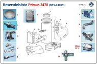
Data plate and production number are located inside the<br />
metal shell beside the expansion vessel.<br />
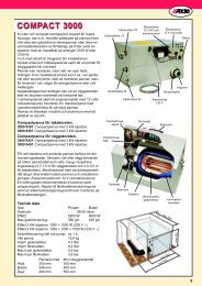
1:0 How the boiler is constructed<br />
The boiler operates with what is known as constant temperature,<br />
i.e. there is always heated liquid in the boiler to<br />
circulate in the system when the room thermostat calls<br />
for heat. In other words there is no time lag when heat<br />
is most needed.<br />
From an air intake on the roof flue terminal, the combustion<br />
air is passed through an aluminium hose into<br />
the combustion chamber. The gas valve and the burner<br />
assembly are attached to an easily removable plate<br />
screwed to the combustion chamber at the bottom of the<br />
boiler. The water jacket, which consists of an inner and<br />
an outer pipe, is located above the combustion chamber.<br />
The space between these pipes constitutes the reservoir.<br />
Inside the inner pipe there is a flame damper which<br />
consists of a folded sheet of metal. Its task is to convey<br />
the hot exhaust gases from the burner out towards the<br />
water jacket so that the water is heated. From the top of<br />
the water jacket, a pipe goes up to the expansion vessel.<br />
In the expansion vessel there is a 12-volt pump which<br />
circulates the heated liquid in the system. On the front of<br />
the boiler is the control panel with thermostat knob, cutout,<br />
power intake and changeover switch. At the top of the<br />
boiler there is a terminal block for making the electrical<br />
connection to the boiler. Beside the boiler, a ventilation<br />
duct is attached that takes in fresh air from outside and<br />
conveys it into the boiler but outside the combustion part<br />
itself. The fresh air is heated by the body of the boiler<br />
and convected through the ventilation grille in the front<br />
panel out into the room.<br />
1:1 Technical data<br />
Gas: Propane Butane<br />
Power: 5,8 kW 6.7 kW<br />
Gas consumption: Max 420 g/h Max 480 g/h<br />
Gas pressure: I 3+<br />
28-30/37 mbar, I 3B/P<br />
30 mbar.<br />
Liquid volume (glycol water) in boiler: 2.6 l.<br />
Liquid volume (glycol water) in immersion heater: 1.0 l.<br />
System temperature in the boiler: 35-75 ° C<br />
2:0 How the boiler works<br />
When the room thermostat calls for heat, the circulation<br />
pump starts. The liquid in the system starts circulating,<br />
and cold water comes into the boiler. The sensor on the<br />
water jacket senses that the water is colder than the temperature<br />
set on the boiler thermostat. The main burner<br />
ignites and heats up the water that circulates round the<br />
system. When the heat inside the vehicle has reached<br />
the temperature set on the room thermostat, the circulation<br />
pump stops. The sensor on the boiler senses that<br />
the water has reached the temperature set on the boiler<br />
thermostat. It shuts off the main burner and goes down<br />
to a pilot flame. When the water temperature has fallen<br />
a few degrees in the boiler, the main flame is lit again.<br />
In this way there is always heated water when the room<br />
thermostat calls for heat.<br />
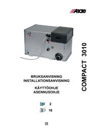
2:1 The functions of the control panel<br />
(fig 1)<br />
A. Normal position for immersion heater. The heating<br />
element is controlled by the room thermostat.<br />
B. Constant position for the immersion heater. The heating<br />
element is controlled by the immersion heaterʼs<br />
thermostat. The changeover switch should be in this<br />
position when the water heater is in use.<br />
C. 1000 watts power on the immersion heater.<br />
D. 2000 watts power on the immersion heater.<br />
E. 240-volt circulation pump on the immersion heater.<br />
F. 12-volt circulation pump on the boiler.<br />
G. Normal position for 12 and 240-volt circulation pumps.<br />
The selected pump starts and stops as indicated by<br />
the room thermostat.<br />
H. Constant position for 12 and 240-volt circulation<br />
pumps. The pump runs constantly and the room temperature<br />
is regulated by the boilerʼs thermostat knob,<br />
in that the boilerʼs system temperature is adjustable.<br />
The constant position uses for example when there<br />
are many persons in the caravan. If one sits near the<br />
room thermostat it can switch the circulation pump<br />
off, with cold areas near the windows and floor as a<br />
result. In this position the pump is constantly on and<br />
coldness is avoided.<br />
I. Cut-out 1 A fuse.<br />
J. Power intake 12 V DC auxilary sockel (used for external<br />
start etc. See chpt 3:0).<br />
K. Warning light for ignition spark.<br />
L. Thermostat knob.<br />
13