Download of Print - Kusters
Download of Print - Kusters
Download of Print - Kusters

You also want an ePaper? Increase the reach of your titles
YUMPU automatically turns print PDFs into web optimized ePapers that Google loves.
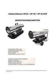
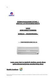
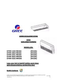
B16,B21<br />
Bedrijfs en Installatievoorschriften<br />
Cassette Type Air Conditioner (Met bedraade afstandbediening)<br />
(3.5-12.3KW)<br />
Binnendeel<br />
GKH12K3CI<br />
GKH18K3CI<br />
GKH24K3CI<br />
GKH30K3CI<br />
GKH36K3CI<br />
GKH42K3CI<br />
Buitendeel<br />
GUHD12NK3CO<br />
GUHD18NK3CO<br />
GUHD24NK3CO<br />
GUHD30NK3CO<br />
GUHD36NK3CO<br />
GUHD36NM3CO<br />
GUHD42NK3CO<br />
GUHD42NM3CO<br />
Lees voor het in bedrijf stellen eerst deze gebruiksaanwijzing<br />
aandachtig door.<br />
RoHS Conform<br />
GREE ELECTRIC APPLIANCES, INC. OF ZHUHAI
Inhoudsopgave<br />
1. Naam en functies van de onderdelen<br />
2. Veiligheid<br />
3. Gebruiker<br />
4. Display onderdelen<br />
4.1 LCD display bedraade afstandbediening<br />
4.2 Instructie LCD display<br />
5. Knoppen<br />
6. Installtie bedraade afstand bediening<br />
7. Instructie bediening<br />
7.1 Aan / uit<br />
7.2 Mode functie instelling<br />
7.3 Temperatuur functie instelling<br />
7.4 Fan functie instelling<br />
7.5 Swing functie instelling<br />
7.6 Timer functie instellen<br />
7.7 Verse lucht instellen*<br />
7.8 Sleep functie instelling<br />
7.9 Turbo functie instelling<br />
7.10 Save instelling<br />
7.11 E-Heater instellen*<br />
7.12 Blow functie instellen<br />
7.13 Quite functie instellen<br />
7.14 Parameter functie<br />
7.15 Andere functies<br />
8. Error display<br />
9. Afstand bediening<br />
10. Instructies installatie<br />
10.1 Installatie opmerkingen<br />
10.2 Installatie cassette unit<br />
10.3 Elektrische bedrading<br />
10.4 Installatie paneel<br />
10.5 Installatie buitendeel<br />
10.6 Producten elektrische installtie<br />
11. Test uitvoeren<br />
12. Optimale instelling<br />
13. Onderhoud<br />
14. Storingen<br />
15. Appendix
1. Naam en functie van de onderdelen<br />
Binnen deel<br />
Buiten deel<br />
GKH12K3CI<br />
GUHD12NK3CO<br />
GKH18K3CI<br />
GUHD18NK3CO<br />
GKH24K3CI<br />
GUHD24NK3CO<br />
GKH30K3CI<br />
GUHD30NK3CO<br />
GKH36K3CI GUHD36NK3CO GUHD36NM3CO<br />
GKH42K3CI GUHD42NK3CO GUHD42NM3CO
2. Veiligheid<br />
Lees eerst deze gebruiksaanwijzing door voor gebruik en installatie van het toestel voor een goede werking.<br />
Het volgende symbool geeft een waarschuwing aan:<br />
Waarschuwing: Dit symbool geeft aan dat het niet goed functioneren letsel kan veroorzaken<br />
Waarschuwing<br />
• Deze unit wordt gebruikt in kantoren, restaurants enz.<br />
• De installatie moet worden uitgevoerd door een erkend bedrijf.<br />
• Installeer de airconditioner op een plaats die het totale gewicht kan dragen.<br />
• Installeer de condensafvoer op de juiste manier, het gevolg kan lekkage zijn.<br />
• Plaats geen licht ontvlambare st<strong>of</strong>fen in de buurt van de airconditioner.<br />
• Schakel het toestel direct uit bij sterke reuk <strong>of</strong> rook verschijnselen.<br />
• Zorg voor een constante lucht doorlaat.<br />
• Steek nooit je vingers in de luchtinlaat <strong>of</strong> Luchtaanzuig.<br />
• Schakel het toestel niet in <strong>of</strong> uit door de voeding direct te onderbreken.<br />
• Het toestel mag niet in vochtige ruimtes worden gemonteerd.<br />
• Controleer voor montage <strong>of</strong> de voeding overeenkomt met het geleverde toestel.<br />
• Controleer voor het inschakelen <strong>of</strong> alles goed is aangesloten en dicht is.<br />
• Zorg voor een goede aarde, die volgens de geldende normen moet zijn aangesloten.<br />
• Eenmaal gestart zal het toestel pas stoppen na ± 5 minuten. Dit voorkomt dat de olie niet meer richting compressor wordt<br />
terug gevoerd.<br />
• Laat het toestel onbeheerd door kinderen bedienen.<br />
• Schakel de voeding uit voor men met onderhoud begint.<br />
• Schakel de voeding uit als het toestel lange tijd niet wordt gebruikt.<br />
• Plaats het toestel niet in een omgeving waar een hoog zuur <strong>of</strong> zout gehalte aanwezig is, informeer hierover eerst bij uw<br />
leverancier.<br />
• Plaats geen voorwerpen op <strong>of</strong> rondom het buitendeel.<br />
• Plaats een werkschakelaar op het buitendeel.<br />
• Alles moet worden aangesloten volgens de geldende richtlijnen, door een erkend bedrijf.
Waarschuwing<br />
Ga niet langdurig in de koude lucht staan<br />
<strong>of</strong> zitten.<br />
Dit kan leiden tot gezondheid klachten.<br />
Let op dat de gebruiken<br />
ophangmaterialen van die kwaliteit<br />
en sterkte zijn dat deze langdurig de<br />
unit kunnen dragen.<br />
Dit kan leiden tot ernstige schade aan<br />
omgeving <strong>of</strong> mensen.<br />
Steek geen handen <strong>of</strong> voorwerpen in de<br />
luchtuitlaat.<br />
Dit kan zeer gevaarlijk zijn.<br />
Ga niet op een buiten deel staan <strong>of</strong><br />
hangen.<br />
Dit kan ernstige schade veroorzaken.<br />
Als men een sterke geur <strong>of</strong> rook ruikt,<br />
schakel dan het toestel uit en neem<br />
contact op met uw leverancier<br />
Hou gevaarlijke en licht ontvlambare<br />
producten uit de buurt van de<br />
airconditioner.<br />
Ze zouden kunnen ontsteken <strong>of</strong><br />
ontbranden.<br />
Blokkeer de luchtuitlaat <strong>of</strong> luchtuitlaat<br />
niet van zowel binnen als buiten unit.<br />
Dit kan leiden tot verminderde capaciteit <strong>of</strong><br />
storing aan de airconditioner.<br />
Gebruik de juiste grootte van<br />
zekering en bedrading.<br />
Foutieve bedrading kan brand<br />
veroorzaken.
Schakel de voeding uit bij langdurig niet<br />
gebruiken van de airconditioner.<br />
Plaats geen open vuur in de<br />
nabijheid van de airconditioner. De<br />
luchtuitstroom kan zorgen voor een<br />
onvolledige verbranding<br />
Trek de stekker niet via de draad uit het stopcontact.<br />
Dit kan voor vlammen zorgen.<br />
Opmerking: Laat kinderen niet onbeheerd de airconditioner bedienen, hou toezicht.
3. Gebruiker<br />
☆ Zorg ervoor dat de voeding voor de binnendelen worden uitgeschakeld als het<br />
buitendeel spanningsloos wordt gemaakt.<br />
☆ Installeer de bekabelde afstandbediening niet op een vochtige plaats <strong>of</strong> in het directe<br />
zonlicht.<br />
☆ Als blijkt dat de airconditioner is geïnstalleerd in een ruimte waar een<br />
elektromagnetisch veld gebruik dan een afgeschermde kabel.<br />
Controleer <strong>of</strong> de communicatie draad is aangesloten op de goede connector, om<br />
storingen te voorkomen.
4. Display<br />
Fig.1 Afbeelding afstandbediening<br />
4.1 LCD Display van de afstandbediening<br />
Fig.2 LCD display
4.2 Verklaring voor LCD Display<br />
Tabel 1<br />
No. Omschrijving Verklaring bediening<br />
1 Swing Swing functie<br />
2 Air * Temperatuur instelling<br />
3 Sleep Slaap functie<br />
4 Running mode Status van het binnendeel (auto mode)<br />
5 Cooling Koel mode<br />
6 Dry Droog mode<br />
7 Fan Ventilator mode<br />
8 Heating Verwarming mode<br />
9 Defrost Ontdooi status<br />
10 Gate-control card Intranet kaart<br />
11 Lock Blokade status<br />
12 Shield Funties afgeschermd via intranet<br />
13 Turbo Turbo functie<br />
14 Memory<br />
Memory state (Toestel komt terug in de positie voor<br />
het uitschakelen van de stroom))<br />
15 Twinkle Knipperd als toestel in bedijf is zonder toetsen.<br />
16 Save Energy-saving ingeschakeld<br />
17 Temperature Ruimte / in te stellen temperatuur<br />
18 E-Heater*<br />
E-HEATER wordt getoond, betekend dat er een<br />
elektrische verwarming beschikbaar is.<br />
19 Blow Nadraaien van ventilator voor drogen verdamper.<br />
20 Timer Tijds instelling voor in – <strong>of</strong> uitschakelen.<br />
21 Quiet Ventilatorgeluid minimaliseren (nachtstand)<br />
Noot: De functies met * zijn niet op alle modellen beschikbaar.
5. Knoppen<br />
5.1 Afdruk van de toetsen<br />
Fig.3 Afdruk van de toetsen<br />
5.2 Instructie en Functie van de toetsen<br />
Tabel.2<br />
No. Omschrijving Uitvoering<br />
1 Enter/cancel<br />
2 ▲<br />
6 ▼<br />
1 Functie selectie en cancel<br />
2 Druk voor 5sec om buitentemperatuur<br />
1 Werking temperatuur instelling van de binnen<br />
unit, bereik :16~30°C<br />
2Timer instelling, bereik: 0.5-24 uur<br />
3Schakelt tussen ‘stil’ en ‘auto stil’.<br />
3 Fan Ventilatorsnelheid hoog/middel/laag/auto.<br />
4 Mode<br />
5 Function<br />
Instelling van koeling / verwarming / ventileren /<br />
drogen van binnendeel<br />
Schakelt tussen de functies van<br />
air/sleep/turbo/save/e-heater/blow/quite<br />
7 Timer Timer instelling<br />
8 On/<strong>of</strong>f Schakelt binnendeel aan / uit<br />
4 Mode<br />
en<br />
2 ▲<br />
Memory<br />
function<br />
Druk Mode en ▲voor 5s als de unit uitgeschakeld is<br />
om enter/cancel memorie functie (Indien memorie<br />
is ingesteld, binnendeel zal in dezelfde functie<br />
verder gaan na inschakelen van de spanning.<br />
2 ▲<br />
en<br />
6 ▼<br />
Lock<br />
Als de unit uitgeschakeld is, druk ▲ ▼ toetsen<br />
tegelijkertijd voor 5s voor toetsenblokkade. De<br />
toetsen zullen niet meer reageren. Druk opnieuw ▲<br />
▼ toetsen voor 5s om de toetsen te ontgrendelen.
6. Installatie bedrade afstandbediening<br />
Fig.4 Schets voor installatie bedrade afstandbediening<br />
No. 1 2 3 4 5<br />
Omschrijving<br />
Basis box<br />
installeren in muur<br />
Bodemplaat van<br />
bediening<br />
Schroef M4X25<br />
Let op volgende punten tijdens installatie van bedrade bediening:<br />
1. Schakel de voeding uit die schade kan toebrengen aan de installatie<br />
Front paneel van<br />
bediening<br />
2. Trek de 4-adrige draad door het montage gat en monteer het via de rechthoek op de plaat.<br />
3. Plaats de bodemplaat in de houder en zet deze vast met de schroeven M4X25.<br />
4. Maak de 4-aderige kabel vast aan de bediening en monteer de bediening in de muur box.<br />
5. Als laatste, monteer het front paneel en bodemplaat vast met schroeven ST2.2X6.5.<br />
Schroef<br />
ST2.2X6.5<br />
LET OP:<br />
Tijdens montage van de draad, let op elektromagnetische spanning dat kan leiden tot foutmelding.<br />
1. Signaal en communicatie draden moeten separaat lopen met de spanning draden. Zorg voor voldoende onderlinge afstand.<br />
2. Gebruik bij voorkeur afgeschermde draden om onderlinge foutmeldingen te voorkomen.
7. Bedienings Instructie<br />
7.1 On/Off<br />
Druk On/Off toets om de unit in te schakelen<br />
Druk opnieuw op de On/Off toets om de unit uit te schakelen.<br />
Noot: de status zoals in Fig.5 geeft aan dat de unit uitgeschakeld is.<br />
De status zoals in Fig.6 geeft aan dat de unit ingeschakeld is..<br />
Fig.5 Uitgeschakelde unit<br />
Fig.6 Ingeschakelde unit<br />
7.2 Mode<br />
Indien de unit ingeschakeld is, druk Mode toets om de volgende instellingen te verkrijgen:<br />
7.3 Temperatuur Instelling<br />
Druk ▲ <strong>of</strong> ▼ toets om de ruimtetemperatuur te verhogen <strong>of</strong> te verlagen als de unit ingeschakeld is.<br />
Als de toets vastgehouden wordt zal de ruimtetemperatuur 1°C bij elke 0.5s verhogen <strong>of</strong> verlagen.<br />
In Koeling, Drogen, Ventileren en Verwarming mode, de temperatuur range is 16°C~30°C.<br />
In Auto mode, de temperatuur is niet handmatig verstelbaar.<br />
Zoals in Fig.7<br />
Fig.7
7.4 Ventilator snelheid instelling<br />
Druk Fan toets, ventilator snelheid van de binnenunit zal wijzigen zoals hieronder:<br />
Zoals in Fig.8<br />
Fig.8
7.5 Swing Control Functie<br />
Indien unit aanstaat, druk ‘Function’ toets totdat de unit swing control functie weergeeft, druk dan Enter/cancel toets om<br />
‘swing’ control functie in te schakelen.<br />
Tijdens swing functie, druk ‘Function’ toets totdat de swing control functie ingeschakeld is en druk ‘Enter/cancel’ toets om<br />
swing control functie uit te schakelen.<br />
Swing control functie instellingen zoals in Fig.9<br />
Fig.9
7.6 Timer Instelling<br />
Druk Timer toets om timer uit te schakelen van de unit. In <strong>of</strong>f-stand van de unit, druk Timer toets om timer in te schakelen<br />
op dezelfde wijze.<br />
Timer on instelling: In <strong>of</strong>f-stand van de unit zonder timer instelling, als Timer toets is ingedrukt, LCD zal display xx hour,<br />
met ON knipperen. In dit geval, druk▲ <strong>of</strong> ▼ toets om timer aan te passen en druk dan Timer voor bevestiging. Als Mode toets<br />
is ingedrukt voor geactiveerde Timer toets ter bevestiging, timer mode zal naar timer OFF instelling wijzigen. In dit geval, LCD<br />
display xx hour, met OFF knipperen. In dit geval, druk▲ <strong>of</strong> ▼ toets om timer OFF te activeren en druk dan Timer toets ter<br />
bevestiging. Indien LCD display xx hour on <strong>of</strong>f, xx hour weergeeft, betekent dit de tijd dat de timer is ON, maar de tijd van de<br />
timer OFF is niet zichtbaar op het display.<br />
Timer <strong>of</strong>f instelling: In on-stand van de unit zonder timer instelling, als Timer toets is ingedrukt, LCD zal display xx hour,<br />
met OFF knipperen. In dit geval, druk▲ <strong>of</strong> ▼ toets om timer aan te passen en druk dan Timer ter bevestiging. Als Mode toets<br />
is ingedrukt voor geactiveerde Timer toets ter bevestiging, timer mode zal naar timer ON instelling wijzigen. In dit geval, LCD<br />
display xx hour, met ON knipperen. In dit geval, druk▲ <strong>of</strong> ▼ toets om timer ON te activeren en druk dan Timer toets ter<br />
bevestiging. Indien LCD display xx hour on <strong>of</strong>f, xx hour weergeeft, betekent dit de tijd dat de timer is OFF, maar de tijd van de<br />
timer ON is niet zichtbaar op het display.<br />
Cancel timer: Indien Timer is ingesteld, als Timer toets is ingedrukt, LCD geeft xx. Hour aan, zodat de timer instelling is<br />
geanuleerd.<br />
Timer <strong>of</strong>f instelling in on-stand van de unit zoals Fig.10<br />
Fig.10 Timer instelling in on stand van de unit<br />
Timer range: 0.5-24 uur. Iedere druk op▲ <strong>of</strong> ▼ toets zal tijdinstelling verhogen <strong>of</strong> verlagen met 0.5 uur.<br />
Indien de toets continu ingedrukt blijft, zal de temperatuur automatisch 0.5 uur bij iedere 0.5 s. verhoogt <strong>of</strong> verlaagt worden.<br />
Noot:<br />
1. Indien timer on en timer <strong>of</strong>f beide ingesteld zijn, de bedrade bediening geeft alleen de tijd van timer <strong>of</strong>f. Indien beide<br />
ingesteld zijn met de unit in <strong>of</strong>f-state, allen de tijd van timer on is weergegeven.
7.7 Verse Lucht Instelling*<br />
In schakelen ‘air Exchange’ functie:<br />
In on-stand van de unit, druk Function toets om naar deze instelling te gaan (Air icoon knippert). AIR 1 weergegeven op het<br />
display geeft de ruimtetemperatuur aan, locatie (888) is foutmelding (de laatste type van AIR zal weergeven worden na<br />
bevestiging). Druk ▲ <strong>of</strong> ▼ toets om air type te wijzigen. Druk Enter/Cancel toets om on/<strong>of</strong>f air functie te wijzigen. Na<br />
inschakelen van deze functie, het air icoon wordt weergegeven.<br />
Dit zijn 10 types van AIR, maar alleen 1-2 types zijn voor de infrarood afstandbediening. Refereer naar de volgende details:<br />
1――De unit werkt continu voor 60min, en verse lucht klep werkt voor 6 min.<br />
2――De unit werkt continu voor 60min, en verse lucht klep werkt voor 12 min.<br />
3――De unit werkt continu voor 60min, en verse lucht klep werkt voor 18 min.<br />
4――De unit werkt continu voor 60min, en verse lucht klep werkt voor 24 min.<br />
5――De unit werkt continu voor 60min, en verse lucht klep werkt voor 30 min.<br />
6――De unit werkt continu voor 60min, en verse lucht klep werkt voor 36 min.<br />
7――De unit werkt continu voor 60min, en verse lucht klep werkt voor 42 min.<br />
8――De unit werkt continu voor 60min, en verse lucht klep werkt voor 48 min.<br />
9――De unit werkt continu voor 60min, en verse lucht klep werkt voor 54 min.<br />
10――De unit werkt continu voor 60min, en verse lucht klep werkt ook continu.<br />
Uitschakelen ‘air Exchange’ functie: Tijdens Air functie, druk ‘Function’ toets voor de instellingen. In dit geval, het air icoon<br />
knippert, en druk dan ‘Enter/cancel’ toets om deze functie uit te schakelen. Air icoon zal iets later verdwijnen op het display.<br />
‘Air Exchange’ instelling zoals Fig.11:<br />
Fig.11 Air exchange
7.8 Sleep Instelling<br />
Sleep on: Druk Function toets in on-stand van de unit naar ‘sleep’ functie en dan druk Enter/cancel toets om ‘sleeping<br />
functie’ in te schakelen.<br />
Sleep <strong>of</strong>f: Tijdens ‘sleep on-stand’, druk Function toets naar ‘sleep’ functie en dan druk Enter/cancel toets om deze<br />
functie uit te schakelen.<br />
‘Sleep’ instelling zoals Fig.12:<br />
Fig.12 Sleep instelling<br />
‘Sleep’ instelling is niet aanwezig na uit en in schakelen van de unit. Er is geen ‘sleep’ functie in ‘fan’ en ‘auto’ mode.<br />
Noot:<br />
In ‘cooling’ en ‘dry’ mode, als de unit met ‘sleep’ functie loopt voor 1 uur, de ingestelde temperatuur zal met 1°C verhoogt<br />
worden en 1°C na weer een 1 uur. Daarna, de unit zal op deze temperatuur blijven. In ‘heating’ mode, als de unit met ‘sleep’<br />
functie loopt voor 1 uur, de ingestelde temperatuur zal met 1°C verlaagt worden en 1°C na weer een 1 uur. Daarna, de unit zal<br />
op deze temperatuur blijven.
7.9 Turbo Functie Instelling<br />
TURBO functie: De unit op hoge ventilator snelheid geeft een snellere koeling <strong>of</strong> verwarming, zodat de ruimtetemperatuur<br />
snel naar de ingestelde temperatuur zal gaan.<br />
In ‘cooling’ <strong>of</strong> ‘heating’ mode, druk Function toets totdat TURBO functie weergegeven wordt druk dan Enter/cancel toets<br />
om TURBO functie in te schakelen.<br />
Tijdens TURBO functie, druk Function toets totdat TURBO functie weergegeven wordt druk dan Enter/cancel toets om<br />
TURBO functie uit te schakelen.<br />
TURBO functie instelling zoals in Fig.13:<br />
Fig.13 Turbo Functie Instelling<br />
Noot:<br />
1. TURBO functie zal na stroomuitval uitgeschakeld worden. In ‘dry’, ‘fan’ en ‘auto’ mode, TURBO functie zal niet werken en het<br />
TURBO icoon wordt niet weergegeven.<br />
2. TURBO functie zal automatisch verdwijnen na inschakelen van de ‘quiet’ functie.
7.10 SAVE Functie Instelling<br />
‘Energy Saving’ Functie: ‘Energy saving’ kan de air conditioner in een kleinere temperatuur bereik laten werken door instelling<br />
van lagere temperatuurwaarde instelling in ‘cooling’ <strong>of</strong> ‘dry’ mode en hogere gelimiteerde waarde in ‘heating’ mode.<br />
Energy Saving Instelling voor ‘Cooling’<br />
In on-stand en in ‘cooling’ <strong>of</strong> ‘dry’ mode van de unit, druk Function toets naar ‘energy saving’ functie, met SAVE knipperen<br />
op het display .Druk ▲ <strong>of</strong> ▼ toets om lagere gelimiteerde temperatuurwaarde in te stellen in ‘cooling’ mode.<br />
Daarna druk Enter/Cancel toets om ‘energy saving’ functie voor ‘cooling’ in te schakelen.<br />
Energy Saving Setting for Heating<br />
In on-stand en in ‘heating’ mode van de unit, druk Function toets naar ‘energy saving’ functie, met SAVE knipperen op het<br />
display. Druk Mode toets naar ‘energy saving’ functie voor ‘heating’ en druk dan▲ <strong>of</strong> ▼ toets om hogere gelimiteerde<br />
temperatuurwaarde in te stellen in ‘heating’ mode.<br />
Daarna druk Enter/Cancel toets om ‘energy saving’ functie voor ‘heating’ in te schakelen.<br />
Nadat ‘energy saving’ functie is ingeschakeld, druk Function toets naar ‘energy saving’ functie en druk Enter/cancel om<br />
deze functie uit te schakelen.<br />
‘Energy saving’ instelling zoals in Fig.14:<br />
Fig.14 Energy Saving Instelling<br />
Noot:<br />
1. In ‘Auto’ mode met ‘save functie’ aan, de unit automatisch gedwongen in ‘Quiet’ Auto Mode en wijzigt de instelling, na<br />
instellen van ‘save’, ‘sleep functie’ zal uitgeschakeld worden.<br />
2. In ‘save’ mode, als Function toets is ingedrukt <strong>of</strong> er is geen activiteit binnen 5s na de laatste werking, het systeem zal ‘quiet’<br />
gaan werken vanaf ‘save’ functie instelling en huidige instelling zal verdwijnen.<br />
3. Na stroomuitval, ‘save’ functie instelling zal opnieuw worden ingeladen en de unit zal op de laatste stand verder doorgaan.<br />
4. De laagste gelimiteerde waarde in ‘cooling’ mode is 16°C en de hoogste gelimiteerde waarde in ‘heating’ mode is 30°C.
7.11 E-HEATER Instelling*<br />
E-HEATER: In de ‘heating’ mode, E-heater kan ingeschakeld worden om het rendement te verhogen. Indien de ‘heating’<br />
mode is ingeschakeld door indrukken van de toets, de electrische verwarming functie zal automatisch worden ingeschakeld.<br />
Druk Function button in ‘heating’ mode en ga naar ‘auxiliary electric heating’ functie, het E-HEATER icoon knippert, en druk<br />
Enter/cancel toets om deze functie in te schakelen. In dit geval, het E-HEATER icoon zal verschijnen, wat betekend dat de<br />
‘E-heater’ ingeschakeld kan worden.<br />
Indien ‘auxiliary electric heating’ functie is ON, druk Function toets ter bevestiging <strong>of</strong> druk Enter/cancel toets voor ‘cancel’.<br />
In dit geval, E-HEATER zal niet op het display verschijnen, wat betekent dat ‘E-heater’ verboden is om uit te schakelen.<br />
De instelling van deze functie zoals in Fig.15:<br />
Fig.15 ‘Auxiliary Electric Heating’ Functie Instelling<br />
Noot:<br />
E-HEATER kan niet ingeschakeld worden in ‘cooling’, ‘dry’ en ‘fan’ mode, E-HEATER icoon wordt niet weergegeven.
7.12 Blow Functie Instelling<br />
BLOW functie: Nadat de unit wordt uitgeschakeld, de verdamper van de binnenunit zal doorgeblazen worden om bacteriële<br />
vervuiling tegen te gaan.<br />
In ‘cooling’ en ‘dry’ mode, druk Function toets totdat BLOW functie verschijnt, met BLOW icoon knipperend, druk dan<br />
Enter/cancel toets om deze functie in te schakelen.<br />
In ‘BLOW’ mode, druk Function toets totdat BLOW functie verschijnt en druk dan Enter/cancel toets om deze functie uit<br />
te schakelen.<br />
BLOW functie instelling in Fig.16:<br />
Fig.16 Blow functie instelling<br />
Noot:<br />
1. Na inschakelen BLOW functie, schakel de unit uit door druk op toets ‘On/Off’ op afstandbediening, ventilator binnendeel zal<br />
op lage snelheid voor 10 min. door blijven draaien (BLOW shows). Als BLOW functie is uitgeschakeld de ventilator binnendeel<br />
zal direct uitgeschakeld worden en niet nadraaien.<br />
2. Er is geen BLOW functie in ‘fan’ <strong>of</strong> ‘heating’ mode.
7.13 Quiet Functie Instelling<br />
Quiet functie bestaat uit: QUIET en AUTO QUIET.<br />
Druk Function toets totdat unit geeft ‘quiet’ functie instelling weer, Quiet <strong>of</strong> Auto Quiet icoon knippert. In dat geval, druk▲<br />
<strong>of</strong> ▼ toets om te wisselen tussen ‘Quiet’ en ‘Auto Quiet’ en druk dan Enter/cancel toets om deze functie in te schakelen.<br />
In ‘quiet’ mode, druk Function toets totdat de unit geeft ‘quiet’ functie. In dat geval, Quiet or Auto Quiet icoon knippert<br />
en druk dan Enter/cancel toets om deze functie uit te schakelen.<br />
Fig.17 Quiet functie instelling<br />
Noot:<br />
1. Tijdens ‘quiet’ functie, is de ventilator snelheid niet instelbaar.<br />
2. Indien de ‘auto quiet’ functie uitgeschakeld wordt, de unit zal in de ‘quiet’ stand verder gaan, volgens de temperatuur<br />
schil tussen ruimte temperatuur en ingestelde temperatuur. In dat geval is de ventilator snelheid instelbaar. Indien de<br />
temperatuur verschil tussen ruimte temperatuur en ingestelde temperatuur ≥ 4°C, de ventilator houdt zijn huidige snelheid;<br />
Indien 2°C≤temperatuur verschil ≤3°C; ventilator snelheid zal gereduceerd wordt met 1 stap, maar als deze al minimum<br />
draait, is deze niet meer verder instelbaar; Indien temperatuur verschil ≤1°C, ventilator snelheid zal minimaal zijn.<br />
3. In ‘auto quiet’ mode, ventilator snelheid kan niet verhoogd <strong>of</strong> verlaagd worden. Indien ventilator snelheid handmatig<br />
wordt ingesteld, ‘auto quiet’ mode zal verdwijnen.<br />
4. Er is geen ‘auto quiet’ functie in ‘fan’ <strong>of</strong> ‘dry’ mode. ‘Quiet’ zal verdwijnen na uitvallen van de spanning.<br />
5. Indien ‘quite’ functie is geactiveerd, ‘turbo’ functie zal uitgeschakeld worden.<br />
7.14 Parameters (Field Settings)<br />
In <strong>of</strong>f-stand van de unit, druk Function en Timer toets voor 5s op naar het ‘debugging’ menu te gaan. Druk Mode toets om<br />
de parameters te bekijken en ▲ <strong>of</strong> ▼ toets om de waarde te wijzigen.<br />
7.14.1 Ruimte Temperatuur Sensor Instelling<br />
In ‘field setting’ mode, druk Mode toets om de temperatuur aan te passen. Display geeft 00 aan, en druk ▲ <strong>of</strong> ▼ toets om<br />
juiste instelling aan te brengen. Er zijn 3 types voor selectie:<br />
Binnen ruimte temperatuur door retourlucht van luchtinlaat (01 instellen)<br />
Binnen ruimte temperatuur door uitblaaslucht (02 instellen)<br />
Retour luchtinlaat temperatuur sensor zal geselecteerd worden voor ‘cooling’, ‘dry’ en ‘fan’ mode en bedrade bediening<br />
temperatuur sensor (03 instellen) zal geselecteerd worden voor ‘heating’ en ‘auto’ mode.<br />
7.14.2 Drie snelheden voor ventilator binnendeel<br />
In ‘field setting’ mode, druk Mode toets om de temperatuur aan te passen (display 01 en druk ▲ <strong>of</strong> ▼ toets om de timer aan<br />
te passen. Er zijn 2 types voor selectie:<br />
3 lage standen (LCD display 01)<br />
3 hoge standen (LCD display 02)<br />
Drie lage standen zijn hoog, medium en laag en drie hoge standen zijn super-hoog, hoog en medium hoog.<br />
Druk Enter/Cancel toets om instellingen te bevestigen en op te slaan.
7.15 Overige Functies<br />
7.15.1 Lock Functie<br />
Druk ▲ en ▼ toetsen tegelijkertijd voor 5s totdat de bedrade bediening in ‘lock’ staat. In dit geval geeft het LCD display: .<br />
Druk opnieuw voor 5s. op dezelfde toetsen om de ‘lock’ stand weer te ontgrendelen.<br />
In ‘lock’ stand, alle toetsen zullen geblokkeerd zijn en nergens op reageren.<br />
7.15.2 Memory Functie<br />
Memory omschakeling: In Off-stand van de unit, druk Mode en ▲ toetsen tegelijkertijd voor 5s om om te schakelen naar de<br />
‘memory’ mode. Tijdens instelling ‘memory’ mode, Memory verschijnt op het display.<br />
Memory herstel: Als memory control is geactiveerd, zal de unit na stroomuitval in dezelfde stand weer inschakelen en zijn<br />
functie vervolgen.<br />
Noot:<br />
Het duurt 5 seconden om alle informatie op te slaan, derhalve, haal geen spanning van de unit.<br />
7.15.3 Buiten temperatuur<br />
In On <strong>of</strong> Off stand van de unit, druk Enter/Cancel toets voor 5s, de buiten temperatuur zal op display verschijnen na een<br />
‘click’ geluid. Na het indrukken van elke willekeurige toets zal dit weer verdwijnen.<br />
7.15.4 Selectie van Graden Celsius <strong>of</strong> Fahrenheit<br />
In Off stand van de unit, druk Mode en ▼ tegelijkertijd voor 5s, het display zal wijzigen in Celsius <strong>of</strong> Fahrenheit.<br />
7.15.5 Master/Slave Bedrade Bediening Instelling<br />
In de Off stand van de unit, druk Enter/Cancel en Mode tegelijkertijd voor 5s om naar de master/slave bedrade bediening<br />
parameters te gaan, druk dan op ▲ <strong>of</strong> ▼ om dit te wijzigen. In dit geval, in de temperatuur display zijn alleen nummers<br />
weergegeven, 01 voor de ‘master wired’ bediening en 02 voor de ‘slave wired’ bediening.<br />
Noot:<br />
Nadien, druk Enter/Cancel om instellingen te bevestigen en menu te verlaten.<br />
Als er maar een bediening aanwezig is, is dit alleen de ‘master’; anders werkt de unit niet goed.<br />
7.15.6 Gate-control Display Functie *<br />
I<br />
Niet van toepassing.
8 Error Display<br />
Als er een storing optreed tijdens het normale bedrijf dan verschijnt dit op de plaats van de temperatuur op het LCD .<br />
Als er meer dan 1 storing is dan verschijnen deze na elkaar op het LCD scherm. Bij gebrijk van meerder systemen, wordt als<br />
eerste het systemnummer gegeven en daarna de storingcode ( niet bij enkelvoudige systemen).<br />
Indien er een storing optreed, schakel het toestel uit en neem contact op met uw dealer.<br />
Het voorbeeld in Fig.18, geeft aan een hoge druk storing in systeen 2.<br />
Verklaring Error codes:<br />
Fig.18<br />
Error code Storing<br />
E0<br />
E1<br />
E2<br />
E3<br />
E4<br />
E5<br />
E6<br />
E9<br />
F0<br />
F1<br />
F2<br />
F3<br />
F4<br />
F5<br />
Condens pomp<br />
Hoge druk beveiliging comporessor<br />
Invries beveiliging binnendeel<br />
Lage druk beveiliging compressor<br />
Hoog persgas temperatuur beveiliging<br />
Compressor overspanning beveiliging<br />
Communicatie fout<br />
Condens bak vol<br />
Ruimte temperatuurvoeler binnendeel (luchtinlaat)<br />
Verdamper sensor defect<br />
Condensor sensor defect<br />
Omgevingstemperatuur sensor buitendeel defect<br />
Discharge temperature sensor malfunction<br />
Ruimte temperatuurvoeler op Display (<strong>of</strong> LED board)<br />
Definitie van storingcodes van DC Inverter buitendeel<br />
Storing<br />
V1.6<br />
Buitendeel display van<br />
twee digits<br />
Binnen<br />
deel<br />
display<br />
DC Overspanningsbeveiliging (voorgemonteerd) PH E5<br />
Oververhitting beveiliging condensor P8 E5<br />
Stroom sensor defect Pc E5<br />
Carbon fin sensor defect P7 E5<br />
Overstroom compressor beveiliging P5 E5<br />
Laga spanning beveiliging PL E5<br />
Opstart compressor beveiliging Lc E5<br />
PFC abnormaal Hc E5<br />
Compressor verstopt LE E5<br />
Drive resetten P0 E5<br />
Compressor modulatie defect H7 E5<br />
Fase ontbreekt Ld E5<br />
Stuurstroom fout richting ho<strong>of</strong>d controle P6 E5<br />
IPM module beveiliging H5 E5<br />
Compressor te hoge snelheid LF E5<br />
Sensor aansluiting beveiliging Pd E5<br />
Temperature drift beveiliging PE E5<br />
AC aansluiting beveiliging P9 E5
Hoge druk beveiliging E1 E1<br />
Lage druk beveiliging E3 E3<br />
Exhaust beveiliging E4 E4<br />
Overstroom compressor beveiliging H3 E5<br />
Communicatie fout E6 E6<br />
Omgevingstemperatuur sensor buitendeel defect F3 F3<br />
Condensor sensor defect F2 F2<br />
Exhaust temperatuur sensor defect F4 F4<br />
Ontdooien (geen storing) 08 defrost<br />
Olie retour (geen storing) 09 no display<br />
Niet juist ingesteld binnendeel LP no display<br />
AC stroom beveiliging (ingang zijde) PA E5<br />
Driver board omgevingstemperatuur sensor defect PF E5<br />
AC ingang spanning beveiliging* PP E5<br />
Electrification loop defect PU E5<br />
Verklaring van de indicatoren op de voorzijde van het paneel (Cassette Unit)<br />
Timer<br />
Indicatie Lamp<br />
(Geel)<br />
Compressor<br />
Indicatie Lamp<br />
(Groen)<br />
Running<br />
Indicatie Lamp<br />
(Rood)<br />
Ontvanger<br />
Verklaring van de drie lampjes op de voorzijde van het cassette paneel.<br />
Timer Indicator Lamp (Geel): knipperd als de Timer is ingeschakeld en is uit als er geen Timer is ingesteld.<br />
Knippert als er een een probleem is met een van de sensoren:<br />
Knippert 1 keer bij een storing binnentemperatuur sensor.<br />
Knippert 2 keer bij een storing verdamper sensor.<br />
Knippert 3 keer bij storing condensor sensor.<br />
Knippert 4 keer bij storing buitentemperatuur sensor.<br />
Knippert 5 keer bij storing ontdooi sensor.<br />
Compressor Indicator Lamp (Groen): Knippert als de compressor is ingeschakeld.<br />
Knippert als er een problem is met de compressor <strong>of</strong> tijdens het ontdooien.<br />
Knippert 1 keer bij een mode conflict.<br />
Knippert 2 keer bij het ontdooien.<br />
Knippert 3 keer bij hogedruk storing.<br />
Knippert 4 keer bij lagedruk storing.<br />
Knippert 5 keer bij overspanning beveiliging.<br />
Knippert 6 keer bij te weinig lucht over de verdamperoverspanning beveiliging.<br />
Running Indicator Lamp (Rood): Knippert als het toestel is ingeschakeld.<br />
Knippert als er een problem is met het binnendeel.<br />
Knippert 1 keer bij goede werking van de communicatie.<br />
Knippert 2 keer bij een te volle condens lekpan.<br />
Knippert 3 keer bij een invries beveiliging.<br />
Knippert 4 keer bij een te hoog gemeten temperatuur.<br />
Knippert 5 keer bij een test run.
9 Afstandbediening<br />
Naam en functie afstand bediening (klep dicht)<br />
Notie:<br />
<br />
<br />
<br />
<br />
Zorg ervoor dat er niets tussen de ontvanger en de afstandsbediening komt.<br />
De afstandsbediening werkt tot een afstand van 10 meter.<br />
De afstandsbediening is niet bestand tegen vallen <strong>of</strong> nat worden.<br />
Plaats de afstandsbediening ook niet in het directe zonlicht <strong>of</strong> op een plaats waar het heet is, en bescherm hem tegen<br />
vloeist<strong>of</strong>fen.<br />
Belangrijk!<br />
De volgende functies zijn bij deze airconditioning niet van toepassing:<br />
SAVE-LIGHT-HUMID-AIR-ANION
Beschrijving van de afstandsbediening (klep open)<br />
<br />
<br />
Sommige toetsen worden niet beschreven omdat deze geen functie hebben.<br />
De functie van deze toetsen hebben geen invloed op de normale werking van het toestel.
Koel functie<br />
Notitie:<br />
Afhankelijk van het verschil tussen de ruimte – temperatuur en de ingestelde temperatuur zal de airconditioning wel <strong>of</strong><br />
niet gaan draaien.<br />
Als de ruimte – temperatuur hoger is dan de ingestelde temperatuur zal de compressor functioneren.<br />
Als de ruimte – temperatuur lager is dan de ingestelde temperatuur zal de compressor stoppen en alleen de ventilator<br />
van het binnendeel zal blijven draaien.<br />
De in te stellen temperatuur ligt tussen 16° C en 30° C.
Verwarming functie<br />
Notitie:<br />
Als de ruimte – temperatuur lager is dan de ingestelde temperatuur dan zal de airconditioner werken als verwarming.<br />
Als de ruimte – temperatuur hoger is dan de ingestelde temperatuur zal de airconditioner stoppen en tevens zal het<br />
buitendeel stoppen. De horizontale lamellen worden nu automatisch recht gezet.<br />
De in te stellen temperatuur ligt tussen 16° C en 30° C.
Droog functie<br />
Als de ruimte – temperatuur lager is dan de ingestelde temperatuur stopt de compressor, de ventilator van het<br />
binnendeel en de ventilator van het buitendeel.<br />
Als de ruimte – temperatuur ligt tussen +/- 2° C van de ingestelde temperatuur dan zal de airconditioner werken als<br />
droger.<br />
Als de ruimte – temperatuur meer dan 2° C bedraagt da de ingestelde waarde dan zal de airconditioner werken volgens<br />
de COOL mode.<br />
De temperatuur is in te stellen tussen 16° C en 30° C.
Auto functie<br />
Notitie:<br />
<br />
Als men de AUTO functie heeft ingeschakeld dan is de standaard ingestelde temperatuur 26° C voor koelen en 24° C<br />
voor drogen en 20° C voor verwarmen.
Fan functie<br />
<br />
<br />
<br />
Druk op ON/OFF.<br />
Druk op Mode en selecteer de “FAN” mode.<br />
Druk op de “Fan” knop om de snelheid te selecteren.
Timer functie<br />
Notitie:<br />
<br />
Met deze functie kan men de airconditioner automatisch in en uit laten schakelen.
Sleep functie<br />
Notitie:<br />
<br />
<br />
Wanneer de airconditioning functioneert in de mode COOL <strong>of</strong> DRY en de sleep toets wordt ingedrukt, dan zal de<br />
ingestelde temperatuur 1° C toenemen in 1 uur en 2° C toenemen in 2 uur.<br />
Wanneer de airconditioning functioneert in de mode Verwarming en de sleep toets wordt ingedrukt, dan zal de<br />
ingestelde temperatuur 1° C afnemen in 1 uur en 2° C afnemen in 2 uur.
10 Instructie voor Installatie<br />
10.1 Installatie opmerkingen<br />
Locatie<br />
• De airconditioner moet deugdelijk worden geïnstaleerd.<br />
• Vermijdt makkelijk bereikbare plaatsen.<br />
• Vermijdt andere warmtebronnen en direct zonlicht.<br />
• Installeer het binnendeel niet in de buurt van radio <strong>of</strong> TV.<br />
• Vermijd ruimtes met onvlambare gassen.<br />
• Bij installatie aan zee <strong>of</strong> vochtige ruimtes neem eerst<br />
contact op met uw dealer.<br />
• Niet installeren in wasserette.<br />
Installatie en Transport<br />
• Installatie en transport moeten worden uitgevoerd door<br />
erkend personeel.<br />
• Gebruik alleen originele ondredelen om storingen te<br />
voorkomen.<br />
• Zorg ervoor dat het toestel op een deugdelijk manier<br />
wordt opgesteld.<br />
Geluid<br />
• Selcteer een plaats met goede ventilatie en waar het geen<br />
geluidshinder kan opleveren.<br />
• Installeer het buitendeel op een ondergrond die het gewicht<br />
kan dragen.<br />
• Selecteer een plaats waar de buurman er geen last van<br />
heeft.<br />
• Plaats geen voorwerpen voor de luchtuitlaat.<br />
• Als na het installeren een abnormaal geluid te horen is neem<br />
dan contact op met uw dealer.<br />
Bedrading<br />
• Zorg ervoor dat de bedrading wordt aangesloten door erkend<br />
personeel.<br />
• Zorg voor een gescheiden zekering.<br />
• De bedrading moet worden uitgevoerd volgens de geldende<br />
normen.<br />
AARDE zorg voor een goede aarde.<br />
Gebruik hiervoor geen gas <strong>of</strong> waterleiding.
10.2 Installatie cassette binnendeel<br />
10.2.1 Schematisch diagram afstanden<br />
H<br />
>20<br />
≥ 15 00<br />
≥ 150 0<br />
Un i t : mm<br />
≥ 1800<br />
Model<br />
H(mm)<br />
GKH12K3CI 250<br />
GKH18K3CI<br />
GKH24K3CI<br />
260<br />
GKH30K3CI<br />
GKH36K3CI<br />
GKH42K3CI<br />
340<br />
10.2.2 Selecteer locatie van het binnendeel<br />
1. Plaats geen obstructies voor de uitblaas van het toestel.<br />
2. Controleer voor het plaatsen de minimale afstanden volgens het schema.<br />
3. Selecteer een plaats die minimale 4 maal het gewicht van het binnendeel kan dragen en geen geluid en vibratie overbrengt.<br />
4. Plaats het toestel horizontaal.<br />
5. Selecteer een plaats waar men eenvoudig de afvoer kan aansluiten en eenvoudig de leidingen met buiten kan aansluiten.<br />
6. Zorg dat er voldoende ruimte is voor onderhoud nadien. Controleer dat de minimale hoogte tussen het binnendeel en de vloer<br />
1800mm bedraagt.<br />
10.2.3 Belangrijk<br />
☆ Om een goede werking te garanderen moet de gehele installatie worden gemonteerd door erkend personeel.
10.2.4 Afmeting van het gat in het plafond en ophangpunten (M10)<br />
GKH12K3CI<br />
GKH18K3CI / GKH24K3CI / GKH30K3CI GKH36K3CI / GKH42K3CI<br />
☆ De montage van de ophanging moet worden uitgevoerd door erkend personeel.<br />
Fig.19<br />
Noties:<br />
De afmeting voor de plafond opening gemerkt met * mogen 910mm zijn. De overlapping van het pafond en de afdekplaat<br />
mogen niet kleiner zijn dan 20mm.
10.2.5 Ophangen binnendeel<br />
1. Instaleer de airconditioner op een vaste plaats.<br />
Monteer de draadstang aan het plafond. Zorg ervoor dat er een carrosseriering onder en boven het ophangpunt van de<br />
airconditioning zit. Het hulpstuk(7) zorgt ervoor dat de carrosseriering niet naar beneden valt.<br />
Gebruik de kartonnen mal (5) om de positie van de airconditioning te bepalen.<br />
Het midden van de airconditioner staat op de mal en het midden van de het plafond staat op de mal, deze moeten beiden<br />
boven elkaar zitten.<br />
Monteer de mal tegen de airconditioner met bij geleverde schroeven (6).<br />
2. Zie figuur 3. hang de airconditioner in de juiste positie.<br />
3. Controleer <strong>of</strong> de airconditioner horizontaal hangt.<br />
<br />
<br />
Het binnendeel is uitgerust met een condenspomp en een niveauschakelaar.<br />
Als het toestel niet recht hangt is het mogelijk dat het water niet weg gepompt wordt en kan zorgen voor een storing.<br />
4. Verwijder het hulpstuk(7)<br />
5. Verwijder de kartonnen mal.<br />
Waarschuwing<br />
Controleer <strong>of</strong> na montage alle moeren vastzitten<br />
10.2.6 Aansluiten van de koelleiding<br />
Afmeting van de koelleiding<br />
Het koelmiddel is R410A, GWP=2020 ODP=0<br />
Fig. 3 Koelleiding selectie<br />
Item<br />
Diameter koelleiding (Inch)<br />
Model Zuig Pers<br />
GUHD12NK3CO<br />
GKH12K3CI<br />
GUHD18NK3CO<br />
GKH18K3CI<br />
GUHD24NK3CO<br />
GKH24K3CI<br />
GUHD30NK3CO<br />
GKH30K3CI<br />
GUHD36NK3CO<br />
GKH36K3CI<br />
GUHD36NM3CO<br />
GKH36K3CI<br />
GUHD42NK3CO<br />
GKH42K3CI<br />
GUHD42NM3CO<br />
GKH42K3CI<br />
Max.<br />
Lengte<br />
(m)<br />
Max Hoogte verschil tussen<br />
binnen en buiten deel<br />
(m)<br />
Extra toe te voegen<br />
Koelmiddel per extra<br />
meter koelleiding<br />
3/8 1/4 20 15 30g/m<br />
1/2 1/4 20 15 30g/m<br />
5/8 3/8 30 15 60g/m<br />
5/8 3/8 50 30 60g/m
Noot:<br />
1. De standaard buis lengte is 5m, Als de lengte van de koelleiding kleiner is <strong>of</strong> gelijk aan 7 m dan hoeft er geen koelmiddel te<br />
worden toegevoegd. Als de koelleiding langer is dan 7m dan moet koelmiddel worden toegevoegd volgens onderstaande tabel.<br />
2. De dikte van de koelleiding moet minimaal liggen tussen 0.5-1.0 mm en de koelleiding moet minimaal een druk van 6.0 MPa<br />
kunnen weerstaan.<br />
3. Hoe langer de koelleiding, hoe minder koel effect en verwarming effect.<br />
Fig.21<br />
Gebruik bij het vastdraaien twee sleutel en waarvan een momentsleutel. Zie fig. 21<br />
☆ Smeer bij het vastdraaien wat koelolie op de koppelingen en draai eerst de koppelingen aan met de hand daarna met de<br />
sleutels.<br />
☆ Controleer table 4 voor de juiste krachten die nodig zijn.<br />
Tabel 4<br />
Diameter(Inch) Kern diameter (mm) Kracht (Nm)<br />
φ1/4 ≥0.5 15-30<br />
φ3/8 ≥0.71 30-40<br />
φ1/2 ≥1 45-50<br />
φ5/8 ≥1 60-65<br />
φ3/4 ≥1 70-75<br />
☆ Controleer de koppelingen op lekkage en isoleer ze daarna goed. Zie fig.21.
10.2.7 Condens aansluiting<br />
1. Installatie van condensbuis<br />
• De diameter van de condensbuis moet groter <strong>of</strong> gelijk zijn dan de diameter van de flexibele aansluittule. 25mm buiten<br />
diameter.<br />
• Hou de condensbuis zo kort mogelijk en laat de buis voldoende aflopen.<br />
• Zorg ervoor dat er geen zakken gevormd kunnen worden.<br />
1-1. 5m<br />
○ (Correct) 1/100 or more gradient<br />
× (wrong)<br />
☆ Gebruik het bijgeleverde aansluitsuk<br />
en de slangklem.<br />
Isoleer het aansluitstuk met de<br />
bijgeleverde isolatie.<br />
Isoleer ook de condensslang afvoer.<br />
● Noot<br />
Clamp<br />
Sponge(attachment)<br />
Clamp(attachment)<br />
☆ Installeer de condensbuis op een<br />
hoogte van 280 mm <strong>of</strong> minder<br />
Sponge (gray)<br />
Drain hose<br />
Below 4mm<br />
Installeer de condensbuis zoals afgebeeld ten opzichte van het binnendeel maar niet meer dan 300 mm vanaf de airconditioner.<br />
2. Instructie<br />
☆ Het hoogte verschil van de condens<br />
Drain hose(attachment)<br />
.<br />
bel ow75mm<br />
bel ow500mm<br />
leiding moet minder zijn dan 75mm.<br />
☆ Monteer de condensleiding volgens onderstaande tekening als er meerdere toestellen op een condensafvoer worden<br />
aangesloten.<br />
Controleer na installatie van de condensleiding <strong>of</strong> het condenswater goed weggevoerd wordt.<br />
Pomp mb.v een fles met een lange hals water in de airconditioner via de luchtinlaat <strong>of</strong> door het inspectiegat.<br />
Als de elektrische aansluiting verder in orde is controleer dan <strong>of</strong> het water weggevoerd wordt. Zie afbeelding
● Waarschuwing: Zorg ervoor dat het toestel spanningsloos is als er aan elektrische onderdelen wordt gewerkt.<br />
10.3. Elektrische bedrading<br />
• Alle elektrische aansluitingen moeten conform de NEN 1010 zijn aangesloten en volgens de plaatselijk geldende normen.<br />
• Voor de elektrische aansluitingen zie schema op iedere unit binnen en buiten.<br />
• Alle bedradingen moeten worden uitgevoerd door een gekwalificeerd persoon.<br />
• Op ieder airconditioner moet een werkschakelaar worden gemonteerd die de gehele airconditioning spanningsloos kan<br />
maken.<br />
• Zorg voor een goede aarde.<br />
• De bedrading moet voldoen aan de geldende normen.<br />
10.3.1<br />
Gebruik bij het aansluiten de juiste doorvoeringen en gebruik de trekontlastingen op de juiste manier.<br />
● Waarschuwing:<br />
Controleer voordat men inschakelt <strong>of</strong> de aansluitingen tussen binnen en buitendeel goed zijn aangesloten.<br />
10.3.2 Connection <strong>of</strong> Signal Line <strong>of</strong> Wire Controller<br />
1. Open de deksel van de elektrische aansluitingen op het binnendeel.<br />
2. Trek de signaal kabel van de afstandsbediening door de rubber ring. P<br />
3. Steek de connector van de afstandsbediening in de 4 pins connector op de printplaat.<br />
4. Gebruik de trekontlasting.
10.4 Installatie van het paneel<br />
1. Houdt het decoratie paneel zoals aangegeven op de tekening.<br />
2. Installeer het decoratie paneel<br />
(1) Monteer de beugels los aan de haken van de airconditioner (zie detail 1) op twee posities<br />
(2) Monteer vervolgens de andere twee beugels (zie detail 2) Let op dat de bedrading van de motor niet tussen de<br />
airco en het paneel komt<br />
(3) Draai de 4 schroeven ± 15 mm naar boven (zie detail 3)<br />
(4) Positioneer hierna het decoratie paneel zo zodat de hele opening wordt afgedekt (zie detail 4)<br />
(5) Draai nu de schroeven verder vast tot de isolatie nog een dikte heeft van ± 5 tot 8mm<br />
Fig. 22<br />
LET OP<br />
1. Niet goed aandraaien van de schroeven kan leiden tot problemen. Fig.23<br />
Fig.23<br />
2. Als er nog steeds een gat is tussen het decor paneel en het plafond verhang dan het<br />
binnendeel. Fig.24<br />
Fig.24<br />
● Controleer na montage <strong>of</strong> er geen gat meer zit tussen plafond en paneel.
3. Bedrading van paneel<br />
Monteer de beide aansluitingen van de swing motor. ( zie fig. 25 )<br />
NOOT: De twee connectoren moeten in de elektrische kast worden geplaatst. Zie fig 25<br />
Connector paneel<br />
ButtedTermin<br />
Fig.25
10.5 Installatie van buitendeel<br />
10.5.1 Afmetingen van buitendeel<br />
Model<br />
tem<br />
GUHD12NK3CO<br />
10.5.2 Schematisch diagram afstanden<br />
GUHD18NK3C<br />
O<br />
GUHD24NK3CO<br />
GUHD30NK3CO<br />
GUHD36NK3CO<br />
GUHD36NM3CO<br />
GUHD42NK3CO<br />
GUHD42NM3CO<br />
A 776 955 980 1107<br />
B 320 396 427 440<br />
C 540 700 790 1100<br />
D 510 560 610 631<br />
E 286 360 395 400<br />
10.5.3 Voorzorgsmaatregelen voor installatie van de buitenunit<br />
1. Selecteer een plaats voor het buitendeel waar de klant het mee eens is.<br />
2. Er moet een goede ventilatie mogelijk zijn.<br />
3. De plaats moet het gewicht van de airconditioner kunnen dragen en geen vibraties veroorzaken.<br />
4. De buren moeten er geen last van hebben.<br />
5. Daar waar geen ontvlambare st<strong>of</strong>fen voorkomen.<br />
6. Er moet voldoende plaats zijn om service te kunnen verlenen.<br />
7. De wind moet niet rechtstreeks er doorheen kunnen blazen.
10.5.4 De drie principes Van koelleiding<br />
Installeer<br />
binnendeel<br />
Snij<br />
koelleiding<br />
op maat<br />
Koppel<br />
koelleiding<br />
Doorspoelen<br />
stikst<strong>of</strong><br />
Solderen Doorspoelen Vacumeren<br />
De drie stappen voor koelleiding montage<br />
Drogen<br />
Oorzaak probleem<br />
• Water, regen, enz.<br />
• Vuil<br />
Actie voorkomen<br />
Koelleiding afdichten – Doorblazen - Vacumeren<br />
Schoon<br />
maken<br />
Lekkage<br />
• Oxide vorming tijdens<br />
solderen<br />
• Smeer, troep, e.d.van<br />
buiteaf<br />
Doorblazen stikst<strong>of</strong><br />
Koelleiding afdichten<br />
• Lekkage soldering<br />
• Lekkage flare<br />
• Lekkage flens Afpersen met stikst<strong>of</strong> en repareren<br />
10.5.5 Voorbereiding koelleiding aansluiting<br />
Voorbereiding koelleiding<br />
1. Leiding & Electrische bedrading<br />
1. Gebruik het juiste gereedschap.<br />
2. Meet nauwkeurig de leidingen.<br />
3. De lengte van de leiding dient iets<br />
langer te zijn dan de gemeten maten.<br />
4. De bedrading dient 1,5 m. langer te zijn<br />
dan de koelleidingen.<br />
Fig.56<br />
2. Afbramen<br />
1. Maak je binnenzijde van de koelleiding goed schoon<br />
2. Bij het afbramen van de koelleiding mogen er geen bramen in de koelleiding<br />
komen. Hou de leiding onderste boven.<br />
3. Flare het koelleiding eind<br />
Flare beide eind van de leiding met flare<br />
Fig.57<br />
gereedschap.<br />
4. Wire Connecting and Taping<br />
(See the figure on right)
10.5.6 Connecting Pipe<br />
1. Richt de flare op het midden van het aan te sluiten koppelstuk en draai vast met de hand.<br />
2. trek daarna de flare / koppeling aan met passende sleutel volgens onderstaande tekening.<br />
Controleer in tabel 5 wat de benodigde kracht is. Te vast kan leiden tot lekkage .<br />
Tabel 5 De maximaal benodigde kracht<br />
Diameter(Inch) kerndiameter(mm) kracht(Nm)<br />
φ1/4 ≥0.5 15-30<br />
φ3/8 ≥0.71 30-40<br />
φ1/2 ≥1 45-50<br />
φ5/8 ≥1 60-65<br />
φ3/4 ≥1 70-75<br />
3. De hoek en de rand van de flare moeten niet te klein en scherp zijn, dit kan lekkage tot gevolg.<br />
4. Probeer solderingen altijd uit te voeren volgens tekening. Geen goede soldering kan lekkage tot gevolg hebben.<br />
5. Isoleer de koelleiding en koppeling vervolgens met isolatie en daarna met PVC tape.<br />
10.5.7 Vacumeren<br />
Het doel van het ontluchten is om zich te ontdoen van vocht en lucht in het systeem. Vocht brengt schade toe aan de compressor<br />
en kan de werking beïnvloeden.<br />
1. Ontluchten door vacumeren<br />
1) Verwijder de kap van de drie weg kraan<br />
2) Sluit de Slangen volgens tekening<br />
rechts.<br />
3) Start de vacuüm pump, en laat deze draaien tot het gewenste vacuum is bereikt .<br />
Doe dit tenminste voor 15 minuten.<br />
4) Verwijder de afdichtingdoppen van de zuig en pers kranen,T<br />
5) Draai de pers kraan open tot de druk op de vacuümmeter 0 bar aangeeft en sluit hierna de kraan weer.<br />
6) Verwijder de pers gas slang.<br />
7) Verwijder de zuiggas slang.<br />
8) Draai vervolgens beide kranen helemaal tot de aanslag open en monteer vervolgend de kappen weer op de kranen en<br />
controleer <strong>of</strong> er geen lekkages zijn.<br />
2. Lekkage controle<br />
1. Controleer d.m.v. zeepsop <strong>of</strong> er lekkages zijn en maak daarna alles goed droog.<br />
2. Breng isolatie weer aan en zorg d.m.v. trekbanden dat de isolatie goed blijft<br />
zitten.
10.5.8 Vloeist<strong>of</strong> – en Condensleiding<br />
Indien de buitenunit lager geïnstalleerd is dan de binnenunit (Fig.626)<br />
1. Een condensleiding dient boven de grond en niet in het water uit te komen<br />
2. . De condensleiding dient d.m.v. ‘zadels’ aan de muur gemonteerd te zijn.<br />
3. De condensleiding dient van boven tot onder vastgelijmd te zijn i.v.m. lekkages.<br />
4. Alle leidingen zijn samen met tape ingepakt en d.m.v. ‘zadels’ aan de muur gemonteerd.<br />
Fig.26<br />
Indien de buitenunit hoger geïnstalleerd is dan de binnenunit. (Fig.27)<br />
1. De condensleiding dient van onder tot boven vastgelijmd te worden i.v.m. lekkages.<br />
2. Alle leidingen zijn gebogen en ingepakt om condenswater in de ruimte te voorkomen.<br />
3. Alle leidingen zijn samen met tape ingepakt en d.m.v. ‘zadels’ aan de muur gemonteerd.<br />
Fig.27<br />
10.5.9 Extra bescherming van koelleidngen<br />
1. Om condenslekkages te voorkomen moeten beiden koelleidingen goed worden<br />
geïsoleerd en samen worden gebonden met isolatie tape.<br />
3. De aansluitingen aan het binnendeel moeten goed worden geïsoleerd om lekkage te<br />
voorkomen zie fig. 28<br />
Fig.28<br />
Waarschuwing:<br />
1) Nadat de koelleidingen zijn geïsoleerd buig deze dan niet meer omdat men niet meer kan controleren <strong>of</strong> ere en lek ontstaat<br />
<strong>of</strong> zelfs afbreken.<br />
2) Omwikkel de isolatie niet te strak, anders verliest de isolatie zijn thermische eigenschappen en kunnen er weer opnieuw<br />
condens problemen ontstaan.<br />
3) Na het isoleren van de koelleidingen en de condensleiding, maak dan ook de oppeningen door dak <strong>of</strong> wand dicht.
10.5.10 Let op bij koelleidingen<br />
Het aanleggen gebeurt normaal volgens de volgende beschrijving.<br />
1. Hou de lengte van de koelleiding zo kort mogelijk (min. 3 meter) het liefst kleiner dan 5 meter.<br />
2. Hou de afstand tussen binnen en buiten deel zo klein mogelijk.<br />
3. Lessen the quantity <strong>of</strong> elbows as much as possible.<br />
4. Als de totale lengte meer dan 20 meter bedraagt controleer dan <strong>of</strong> de olie op de juiste manier wordt terug gevoerd. Als dit niet<br />
het geval is plaats dan een olietrap. Zie fig. 29<br />
5. Het koelmiddel in het buitendeel is toereikend voor 7 meter koelleiding. Bij ieder meter langer zie Tabel 3 voor bijvulling.<br />
6. Als het hoogte verschil tussen binnen en buitendeel meer is dan 10 meter plaats dan een olie trap volgens fig. 29.<br />
Persgas (dunne buis)<br />
- - - - - - Zuiggas (dikke buis)<br />
Fig.29<br />
10.5.11 Positie en Methode voor installeren van bedraade afstandsbediening<br />
1. Een uiteinde van de kabel wordt op de printplaat van het binnendeel gemonteerd en het andere uiteinde aan de<br />
afstandsbediening. Gebruik de daarvoor bestemde trekontlasting om de kabel vast te zetten. De mee geleverde kabel heeft<br />
een lengte van 8 meter.<br />
2. Gebruik geen metalen leidingen om de draad voor de afstandsbediening door te voeren. De draad kan verlengd worden, dit<br />
moet echter door de installateur gedaan worden.<br />
3. Kies eerst in plek om de afstandsbediening te monteren.<br />
4. Als de afstandsbediening op een wand wordt gemonteerd maakt dan gebruik van een goot <strong>of</strong> een buis zie fig. 30. Bij montage<br />
op een holle wand zie Fig. 31.<br />
5. Monteer de afstandsbediening op de wand en controleer <strong>of</strong> deze goed is bevestigd. Zie Fig. 4<br />
Fig.30<br />
Fig.31<br />
Let op:<br />
Let bij de montage op dat de bodemplaat op de juiste manier wordt gemonteerd, de twee nokjes moeten beneden<br />
zitten, anders komt de afstandsbediening op de kop te hangen<br />
Caution:<br />
1. De communicatie afstand tussen print en afstandsbediening mag maximaal 20 meter bedragen. (Standaard 8 meter)<br />
2. De afstandsbediening mag niet in vochtige ruimten worden geïnstalleerd <strong>of</strong> op plaatsen waar de bediening nat kan worden.
10.5.12 Voeding<br />
Waarschuwing: Voor het installeren van de elektrische bedrading controleer de onderstaande punten:<br />
1) Controleer <strong>of</strong> de voeding overeenkomt met de gegevens op de naamplaat.<br />
2) De capaciteit van de stroomvoorziening genoeg zijn zie tabel 6.<br />
3) De voeding moet worden aangesloten door erkend personeel.<br />
Het is verplicht om een werkschakelaar te plaatsen.<br />
2 Aansluiten draad<br />
1) Zie afbeelding<br />
Warning:<br />
1) De voeding en alle elektrische aansluiting dienen door erkend personeel worden aangesloten, volgens de geldende<br />
richtlijnen.<br />
10.5.13 aansluiten voedingskabel<br />
1. Air-conditioning 230 volt een fase<br />
1) Verwijder de kap van de elektrische aansluitingen op het buitendeel.<br />
2) steek de kabel door de rubberring,<br />
3) Sluit de voeding aan op “L, N”<br />
4) Gebruik de trekontlasting om de kabel vast te zetten<br />
2. Air-conditioning 380v drie fase<br />
1) Verwijder de kap van de elektrische aansluitingen op het buitendeel.<br />
2) steek de kabel door de rubberring,<br />
3) Sluit de voeding aan op “L1,L2,L3 en N”<br />
4) Gebruik de trekontlasting om de kabel vast te zetten<br />
10.6 Elektrische installtie<br />
Waarschuwing!<br />
Zorg ervoor dat de airconditioner deugdelijk is geaard<br />
Bedrading<br />
<br />
<br />
<br />
<br />
De installatie moet voldoen aan de nationale regelgeving.<br />
In ieder binnen en buitendeel is een schema aan de binnenzijde van de elektrische bescheschermkap geplakt<br />
Er dient op ieder buitendeel een werkschakelaar te worden geplaatst.<br />
In tabel 6 vind u de minimale aderdoorsnedes en amperage van de betreffende units. T
Model<br />
Tabel 6<br />
Voeding<br />
(V, Ph, Hz)<br />
Afzekerwaarde<br />
werkschakelaar<br />
(Buiten/binnen)<br />
Bedrading<br />
(mm2)<br />
(Buiten/binnen)<br />
(A) (mm 2 )<br />
GUHD12NK3CO/GKH12K3CI 16/6.0 2.5/1.0<br />
GUHD18NK3CO/GKH18K3CI 20/6.0 4.0/1.0<br />
GUHD24NK3CO/GKH24K3CI 220-240, 20/10 4.0/1.5<br />
GUHD30NK3CO/GKH30K3CI<br />
~,50<br />
32/10 6.0/1.5<br />
GUHD36NK3CO/GKH36K3CI 32/10 6.0/1.5<br />
GUHD42NK3CO/GKH42K3CI<br />
32/10 6.0/1.5<br />
GUHD36NM3CO/GKH36K3CI 380-415, 25/10 6.0/1.5<br />
GUHD42NM3CO/GKH42K3CI<br />
3N~,50<br />
25/10 6.0/1.5<br />
1. Als de afstand tussen toestel en zekering groter is dan 15 meter controleer dan <strong>of</strong> de gebruikte kabel een voldoende grote<br />
diameter heeft.<br />
De voeding, communicatie kabel aansluiting tussen binnen en buiten<br />
De diameter van de kabels mogen niet kleiner zijn dan hieronder aangegeven. De signaal kabel moet een afgeschermde<br />
kabel zijn.<br />
Schematisch diagram van aansluitingen<br />
GUHD12NK3CO + GKH12K3CI<br />
Voeding 3x2.5mm 2 (H07RN-F) Data 3x1.0mm 2 (H05V V-F)<br />
Communicatie 2×AWG24#<br />
GUHD18NK3CO + GKH18K3CI<br />
Voeding 3x4.0mm 2 (H07RN-F) Data 3x1.0mm 2 (H05V V-F)<br />
Communicatie 2×AWG24#<br />
GUHD24NK3CO + GKH24K3CI<br />
Voeding 3x4.0mm 2 (H07RN-F) Data 3x1.5mm 2 (H05V V-F)<br />
Communicatie AWG24#<br />
GUHD30NK3CO + GKH30K3CI<br />
GUHD36NK3CO + GKH36K3CI<br />
GUHD42NK3CO + GKH42K3CI<br />
voeding 3x6.0mm 2 (H07RN-F) Data 3x1.5mm 2 (H05V V-F)<br />
Communicatie 2×AWG24#<br />
GUHD36NM3CO + GKH36K3CI<br />
GUHD42NM3CO + GKH42K3CI<br />
Voeding 5x 6.0mm 2 (H07RN-F) Data 3x1.5mm 2 (H05V V-F)<br />
Communicatie 2×AWG24#
11. Test<br />
11.1 Voorbereiding voor test<br />
(1) Scakel de voeding niet eerder in voordat de complete installatie is voltooid.<br />
(2) Controleer alle bedrading.<br />
(3) Controleer <strong>of</strong> beide kranen van het buitendeel open staan.<br />
(4) Verwijder alle st<strong>of</strong> en losse onderdelen.<br />
11.2 Testen<br />
(1) Schakel de voeding in en druk op de ON/OFF knop.<br />
(2) Controleer achtereenvolgens alle functies COOL, Heat, Fan, etc..<br />
11.3 Nood bedrijf.<br />
Als de batterijen van de afstandsbediening leeg zijn handel dan als volgt.<br />
* Als het toestel uit staat druk dan op AUTO. Het toestel werkt dan in de automatische mode.<br />
Door nog een keer op Auto te drukken stopt de unit.<br />
Noot: De “TEST” knop op het panel is special bedoeld om het toestel testen. Met deze knop wordt het toestel geforceerd<br />
gestart en zullen alle beveiliging worden uitgeschakeld. Druk hier niet op wanneer het toestel normaal in bedrijf is.<br />
De volgend items , hebben speciale aandacht nodig tijdens installatie en na voltooien van de installatie.<br />
Items te controleren<br />
Is het binnendeel goed gemonteerd?<br />
Is de gaslektest uitgevoerd<br />
Is alles goed geïsoleerd?<br />
Wordt het condens water goed afgevoerd?<br />
Komt de voeding overeen met die op de naamplaat?<br />
Is alle bedrading en koelleiding in orde?<br />
Is het toestel goed geaard?<br />
Is de diameter van de voeding correct?<br />
Kan de unit vrij uitblazen zowel binnen als buiten?I<br />
Is de lengte van de koelleiding gecontroleerd en<br />
bijgevuld?<br />
Indien niet goed wat gebeurt er dan?<br />
Toestel kan vallen, lawaai maken..<br />
Slechte <strong>of</strong> geen koeling.<br />
Condenswater lekkage.<br />
Condenswater lekkage.<br />
Kortsluiting <strong>of</strong> beschadiging van elektrische onderdelen.<br />
Kortsluiting <strong>of</strong> beschadiging van elektrische onderdelen.<br />
Risico van elektrische lekkage.<br />
Kortsluiting <strong>of</strong> beschadiging van elektrische onderdelen.<br />
Slechte <strong>of</strong> geen koeling.<br />
Er ontbreekt koelmiddel waardoor slecht koeleing.<br />
Noote voor de installateur:<br />
Zorg ervoor dat de gebruiker goed is uitgelegd hoe het toestel werkt en geef hem deze handleiding.<br />
De voeding moet binnende toleranties vallen (+/-10%, +/-1Hz).<br />
De omgevingstemperatuur moet liggen tussen 5-40°C, en de vochtigheid moet liggen tussen 30%-95%.<br />
Transport/opslag temperatuur moet liggen tussen -25-55°C
12. Optimale werking<br />
Stel de ruimte temperatuur juist in<br />
Stel de ruimte temperatuur juist in voor een comfortabel<br />
klimaat<br />
Plaats niets onder het binnendeel wat droog moet blijven<br />
Er kan water uit het binnendeel komen als de relatieve<br />
vochtigheid hoger is dan 80% <strong>of</strong> als de afvoer verstopt is.<br />
Schakel de voeding uit wanneer het toestel langer tijd niet wordt gebruikt<br />
Het toestel verbruikt ook energie als het niet wordt gebruikt<br />
Sluit ramen en deuren tijden gebruik<br />
Het koelen en verwarmen wordt beïnvloed door het openstaan<br />
van ramen en deuren.<br />
Plaats radio en tv niet in de buurt van het toestel<br />
Dit kan storing veroorzaken op radio <strong>of</strong> TV
13. Verzorging en onderhoud (moet gebeuren de erkend personeel)<br />
Schakel eerst de voeding uit voordat met onderhoud wordt begonnen.<br />
Schoonmaken van de Filter<br />
1. Open de aanzuig grille<br />
2. Gebruik een schroevendraaier om twee schroeven te<br />
verwijderen<br />
3. Schuif de beide klemmen naar binnen en laat<br />
voorzichtig de grille zakken.<br />
4. Verwijder de luchtfilters<br />
5. Reinig de luchtfilters, gebruik hiervoor een st<strong>of</strong>zuiger<br />
<strong>of</strong> spoel deze af met lauw warm water.<br />
Noot:<br />
Reinig niet met warm water (> 60°C)<br />
Droog niet boven een warmtebron<br />
Laat het toestel niet draaien zonder filter<br />
6. Monteer de luchtfilter<br />
7. Sluit de grille Zie stap 1
Storingen<br />
★ Waarschuwing<br />
● In geval van abnormale werking <strong>of</strong> een sterke brandlucht schakel meteen het toestel uit en neem contact op met uw dealer.<br />
● Ga niet zelf proberen om uw airconditioner te repareren laat dit over aan vakmensen.<br />
★Controleer eerst onderstaande dingen voor contact op te nemen met uw dealer.<br />
symptoom Oorzaak Maatregelen<br />
Fase verwisselt <strong>of</strong> zekering<br />
stuk.<br />
Draai fase om <strong>of</strong> plaats<br />
een nieuwe zekering.<br />
Voeding uit<br />
Toestel start als voeding<br />
opnieuw is ingeschakeld<br />
Het toestel start op<br />
Losse stekker verbinding Steek de stekker goed in<br />
geen enkel manier.<br />
Batterijen van de<br />
Plaats nieuwe batterijen.<br />
afstandsbediening zijn leeg<br />
Afstandsbediening reageert<br />
niet<br />
Hou de afstand binnen 10<br />
meter.<br />
Het systeem stopt<br />
gelijk na de start.<br />
Toestel blaast tegen iets aan,<br />
retour lucht wordt<br />
Verwijder obstakel<br />
opgezogen<br />
Toestel blaast tegen iets aan,<br />
retour lucht wordt<br />
Verwijder obstakel<br />
opgezogen<br />
Verkeerde<br />
temperatuurinstelling<br />
Zie beschrijving<br />
afstandsbediening<br />
Lage ventilator snelheid Zie beschrijving<br />
Slecht koeling en<br />
verwarming<br />
Lucht uitblaas is niet goed<br />
Deuren en ramen open<br />
Direct zonlicht<br />
Te veel mensen in de ruimte<br />
Te veel warmte bronnen<br />
Smerige filters<br />
afstandsbediening<br />
Zie beschrijving<br />
afstandsbediening<br />
Sluit deze<br />
Sluit gordijnen <strong>of</strong><br />
zonwering<br />
Maak deze schoon<br />
★ Noot: Als de storing blijft neem dan contact op met uw dealer.<br />
Als de air-conditioning slecht werkt <strong>of</strong> een storing heeft, controleer dan eerst de volgende punten voor reparatie:<br />
storing<br />
Mogelijke reden<br />
1. De voeding is niet aangesloten.<br />
2. Zekering stuk, werkschakelaar stuk.<br />
Het toestel kan niet worden<br />
3. Te lage voedingspanning.<br />
ingeschakeld.<br />
4. De bedieningstoetsen zijn geblokeerd.<br />
5. Het voorwaarden circuit heeft een storing.<br />
De unit werkt even en schakeld<br />
daarna uit.<br />
Slechte koeling.<br />
Slechte verwarming<br />
De ventilator start niet tijdens<br />
verwarmen<br />
Noot:<br />
1. Er staat iets voor de air-conditioner.<br />
2. Iets in het voorwaarde circuit geeft een storing.<br />
3. Iets in het voorwaarden circuit geeft een storing<br />
4. de omgevingstemperatuur is boven de 52°C.<br />
1. De lucht filters zitten dicht.<br />
2. Teveel warmtebronnen <strong>of</strong> te veel mensen in de betreffende ruimte.<br />
3. De deur <strong>of</strong> het raam staat open.<br />
4. Er staat iets voor de lucht inlaat <strong>of</strong> uitblaas.<br />
5. De ingestelde temperatuur is te hoog.<br />
6. Er is een koelmiddel lekkage.<br />
7. De ruimte temperatuur sensor heeft een storing.<br />
1. De luchtfilters zitten dicht<br />
2. Er staan deuren <strong>of</strong> ramen open.<br />
3. De ingestelde temperatuur is te laag<br />
4. Er is een koelmiddel lekkage..<br />
5. De buitentemperatuur is lager dan -7°C.<br />
1. De buis sensor van het binnendeel zit niet goed..<br />
2. De buis sensor zit niet goed op de printplaat.<br />
3. De kabel van de buis sensor is stuk.<br />
4. De condensator van de motor is stuk <strong>of</strong> de motor zelf<br />
1、Als na controle van alle bovenstaande gegevens en alle metingen de air-conditioner nog steeds niet werkt, neem dan contact<br />
op met uw dealer.
★ De volgende zijn geen storingen<br />
De unit start<br />
niet als<br />
Er komt damp<br />
uit de unit<br />
Buitenunit is<br />
heet<br />
Geluid<br />
St<strong>of</strong> uit de unit<br />
Lucht<br />
ruikt<br />
uitblaas<br />
“storing”<br />
Herstart na stoppen<br />
Temp instellen en gelijk veranderen<br />
Voeding net is ingeschakeld<br />
Tijdens het koelen<br />
Nadat de unit is gestopt.<br />
Piep bij het starten.<br />
Geluid van lopend water tijdens de<br />
werking.<br />
Een puls geluid direct na de start <strong>of</strong><br />
na de stop.<br />
Een trillend geluid<br />
Een krakend geluid tijdens het in<br />
bedrijf zijn.<br />
Na het starten na een lange stilstand<br />
periode<br />
Tijdens de werking<br />
Reden<br />
Als het toestel is gestopt dan treed eerst<br />
een beveiliging van 3 minuten in.<br />
Wacht eerst 1 minuut<br />
De ruimte is snel afgekoeld en wordt<br />
vochtig.<br />
De compressor is heet en kan zo weer<br />
opnieuw starten.<br />
Dit is het ontvangst geluid<br />
Dit is het koelmiddel wat door het<br />
systeem gaat.<br />
Dit is het geluid van het koelmiddel dat<br />
in het buitendeel wordt omgekeerd <strong>of</strong><br />
wordt tegengehouden.<br />
De condenspomp is het water uit de<br />
lekpan aan het pompen.<br />
Door de kou <strong>of</strong> warmte werkt het toestel<br />
door uit te zetten <strong>of</strong> te krimpen.<br />
Het st<strong>of</strong> wordt door het binnendeel<br />
uitgeblazen.<br />
Dit komt door de opgenomen lucht uit<br />
de ruimte.
14. Appendix<br />
Air Conditioner Normale Werking Condities:<br />
Test Conditie<br />
Binnen gedeelte<br />
Buiten gedeelte<br />
DB(°C) WB(°C) DB(°C) WB(°C)<br />
Nominale Koeling 27 19 35 24<br />
Nominale Verwarming 20 — 7 6<br />
Vermogen Koeling 32 23 43 26<br />
Lage Temp. Koeling 21 15 18 —<br />
Vermogen Verwarming 27 - 24 18<br />
Lage Temp.<br />
Verwarming<br />
20 — -7 -8<br />
Noot:<br />
1. Het ontwerp van deze unit conforms de EN14511 standaard.<br />
2. De luchthoeveelheid is gemeten op 0 Pa externe statische druk.<br />
3. Koeling (verwarming) capaciteit is gemeten onder normale condities en met 0 Pa externe statische druk.
Gree Electric Appliances,Inc. <strong>of</strong> Zhuhai<br />
Jin Ji West Road, Qianshan, Zhuhai, Guangdong 519070 P.R. China<br />
http: //www. gree.com<br />
GREE 66175229
A/A DC INVERTER U-MATCH AIR CONDITIONERS<br />
INSTALLATION<br />
Fig.56<br />
GUHD12NK3CO + GKH12K3CI<br />
GUHD18NK3CO + GKH18K3CI<br />
GUHD24NK3CO + GKH24K3CI<br />
GUHD30NK3CO + GKH30K3CI<br />
GUHD36NK3CO + GKH36K3CI<br />
GUHD42NK3CO + GKH42K3CI<br />
GUHD12NK3CO + GKH12K3CI<br />
Power cord 3x2.5mm 2 (H07RN-F) Power cord 3x1.0mm 2 (H05V V-F)<br />
Communication Cords<br />
GUHD18NK3CO + GKH18K3CI<br />
Power cord 3x4.0mm2 (H07RN-F) Power cord 3x1.0mm 2 (H05V V-F)<br />
Communication Cords<br />
GUHD24NK3CO + GKH24K3CI<br />
Power cord 3x4.0mm 2 (H07RN-F) Power cord 3x1.5mm 2 (H05V V-F)<br />
Communication Cords<br />
GUHD30NK3CO + GKH30K3CI<br />
GUHD36NK3CO + GKH36K3CI<br />
GUHD42NK3CO + GKH42K3CI<br />
Power cord 3x6.0mm 2 (H07RN-F) Power cord 3x1.5mm 2 (H05V V-F)<br />
Communication Cords<br />
Fig.57<br />
GUHD36NM3CO + GKH36K3CI<br />
GUHD42NM3CO + GKH42K3C<br />
GUHD36NM3CO + GKH36K3CI<br />
GUHD42NM3CO + GKH42K3CI<br />
Power cord 5x 6.0mm 2 (H07RN-F) Power cord 3x1.5mm 2 (H05V V-F)<br />
Communication Cords<br />
97
A/A DC INVERTER U-MATCH AIR CONDITIONERS<br />
MAINTENANCE<br />
1 TROUBLE TABLE<br />
Table 1 Fault Display on Indoor Wired Controller:<br />
MAINTENANCE<br />
Trouble<br />
Code<br />
Trouble<br />
Name<br />
Origin <strong>of</strong><br />
Trouble Signal<br />
Control Description<br />
E0<br />
Water Pump<br />
Malfunction<br />
Water pump<br />
If the water-full protection cannot be recovered after 2 hours, it is<br />
believed that the water pump is failed, in which case all the loads will<br />
be switched <strong>of</strong>f and cannot be recovered automatically.<br />
E1<br />
High Pressure<br />
Protection <strong>of</strong><br />
Compressor<br />
High-pressure<br />
Switch<br />
When high pressure protection is detected for 3 seconds successively,<br />
all the loads (except the heating 4-way valve) will be switched <strong>of</strong>f, in<br />
which case all the keys and remote control signals except ON/OFF<br />
function will be disabled and cannot be recovered automatically. To<br />
eliminate the fault, it is needed to switch <strong>of</strong>f and on the machine or<br />
recover from power failure.<br />
E2<br />
Indoor<br />
Anti-frozen<br />
Protetion<br />
Indoor<br />
evaporator<br />
sensor<br />
If detecting that the evaporator sensor is lower than protective temp.<br />
value after the unit has been running for a period <strong>of</strong> time under cooling<br />
or dry mode, the unit will report this fault, in which case the compressor<br />
and outdoor fan will be stopped. The unit will not run until this<br />
temperature exits the pretective temperature value and the compressor<br />
is stopped for 3 minutes.<br />
E3<br />
Low Pressure<br />
Protection <strong>of</strong><br />
Compressor<br />
Low-pressure<br />
Switch<br />
If it is detected within 30 seconds successively that the low-pressure<br />
switch is cut <strong>of</strong>f under ON or standby state (If the compressor is started,<br />
the detection will start 3 minutes after the compressor has run), the unit<br />
will report this fault. For the first two faults within 30 minutes, the unit<br />
can be recovered automatically. If over three times, the unit cannot be<br />
recovered automatically.<br />
E4<br />
Air Discharge<br />
High-temperatur<br />
e Protection <strong>of</strong><br />
Compressor<br />
Exhaust<br />
Overtemperatur<br />
e Protection<br />
After the compressor is started, if it is detected within 30 seconds<br />
successively that the exhaust temperature is 130 or higher, E4 will be<br />
displayed, in which case all the loads (except the 4-way valve <strong>of</strong><br />
heating) will be stopped. The complete unit can only be recovered until<br />
the compressor has stopped for 3 minutes and the exhaust<br />
temperature is lower than 90 . For this protection occurs three times,<br />
the complete unit cannot be recovered automatically.<br />
E5<br />
Overload<br />
Proection <strong>of</strong><br />
Compressor<br />
Compressor<br />
After the unit is energized, if it is detected within 3 seconds<br />
successively that the compressor overload switch is cut <strong>of</strong>f, it will be<br />
deemed compressor overload protection. In this case, all the loads will<br />
be stopped (except the 4-way valve <strong>of</strong> heating) and E5 will be<br />
displayed. If the fault is eliminated, the compressor will be restarted<br />
after 3 minutes. If three compressor overload protections are detected<br />
successively in 30 minutes from the first detection to the occurrence <strong>of</strong><br />
fault, the compressor cannot be recovered automatically and the<br />
buzzer will alarm. You shall need to press ON/Off to stop the unit and<br />
clear the sound alarm before pressing ON/OFF again. The unit will be<br />
restarted if the high pressure protection disappears; otherwise the fault<br />
code will be displayed. Besides, “E5” also will also be displayed on the<br />
controller in the event <strong>of</strong> an error <strong>of</strong> the compressor drive module.<br />
E6<br />
Communication<br />
s Failure<br />
If the outdoor unit does not receive data from indoor unit for 30 seconds<br />
successively once energized, this indicates indoor communication<br />
failure. In this case, the compressor and outdoor fan will be stopped.<br />
Under heating mode, the 4-way valve will be stopped if the compressor<br />
Communication has been stopped for 2 minutes. If the indoor unit does not receive<br />
between indoor message from outdoor unit for 1 minute, this indicates communication<br />
and outdoor failure. In this case, the indoor unit will be stopped and the indicator will<br />
mainboard blink. If the display board does not receive message from outdoor unit<br />
in 1 minute, it can be judged that it is communication failure, in which<br />
case the fault will be displayed and the machine will not function. After<br />
the communication is resumed to normal, the system will run as per the<br />
working mode before. This can recover automatically.<br />
E9<br />
Full Water<br />
Protection<br />
Liquid level<br />
switch<br />
If “full water” is detected for 8 seconds successively once energized,<br />
the system will enter into full water protection and the indicator will blink<br />
100
A/A DC INVERTER U-MATCH AIR CONDITIONERS<br />
Trouble Trouble Origin <strong>of</strong><br />
Code Name Trouble Signal<br />
Control Description<br />
MAINTENANCE<br />
(or display E9): Under cooling and dry mode, the outdoor fan and<br />
compressor will be stopped, while the indoor fan will be stopped after 1<br />
minute. Under heating mode, the outdoor fan and compressor will be<br />
stopped, the 4-way valve will maintain its original state, and the indoor<br />
unit will be stopped after 1 minute. Under fan mode, the indoor loads<br />
will not be stopped.<br />
F0<br />
Malfunction Of<br />
Indoor<br />
Environment<br />
Sensor at<br />
Return air Vent<br />
Indoor room<br />
sensor<br />
If the indoor sensor is detected <strong>of</strong> open circuit or short circuit for 5<br />
seconds successively, the indoor room temperature will forcibly set to<br />
24 . In this case, the system will not perform any treatment, only the<br />
indicator will blink or display the fault code. The system can<br />
automatically resume after the failure is eliminated. Under fan mode,<br />
only the fault will be displayed, but the indoor unit will run normally. The<br />
fault disappears after it is eliminated.<br />
F1<br />
Evaporator<br />
Temp. Sensor<br />
Malfunction<br />
Outdoor<br />
evaporator<br />
sensor<br />
If the evaporator sensor is detected <strong>of</strong> open circuit or short circuit for 5<br />
seconds successively: When under cooling and dry mode, the system<br />
will be stopped. When under heating mode, all <strong>of</strong> the loads except the<br />
4-way valve will be stopped, while the indicator will blink or display the<br />
fault code F1. After the fault is eliminated, the system can automatically<br />
resume to operation and clear the fault display. Under fan mode, only<br />
the fault will be displayed, and the indoor unit will run normally. The<br />
fault disappears after it is eliminated.<br />
F2<br />
Condenser<br />
Temp. Sensor<br />
Malfunction<br />
Outdoor<br />
condenser<br />
sensor<br />
If the condenser sensor is detected <strong>of</strong> open circuit or short circuit for 5<br />
seconds successively: When under cooling and dry mode, the system<br />
will be stopped. When under heating mode, all <strong>of</strong> the loads except the<br />
4-way valve will be stopped, while the indicator will blink or display the<br />
fault code F2. After the fault is eliminated, the system can automatically<br />
resume to operation and clear the fault display. Under fan mode, only<br />
the fault will be displayed, and the indoor unit will run normally. The<br />
fault disappears after it is eliminated.<br />
For cooling-only unit, the other units except the duct type will not detect<br />
the condenser sensor fault.<br />
F3<br />
Outdoor<br />
Environment<br />
Sensor<br />
Malfunction<br />
Outdoor<br />
environment<br />
sensor<br />
If the outdoor environment sensor is detected <strong>of</strong> open circuit or short<br />
circuit for 5 seconds successively: When under cooling and dry mode,<br />
the system will be stopped. When under heating mode, all <strong>of</strong> the loads<br />
except the 4-way valve will be stopped, while the indicator will blink or<br />
display the fault code F3. After the fault is eliminated, the system can<br />
automatically resume to operation and clear the fault display. Under fan<br />
mode, only the fault will be displayed, and the indoor unit will run<br />
normally. The fault disappears after it is eliminated.<br />
F4<br />
Malfunction <strong>of</strong><br />
Exhaust Temp.<br />
Sensor<br />
Exhaust<br />
temperature<br />
sensor<br />
If the outdoor temperature sensor is detected <strong>of</strong> open circuit for 5<br />
seconds successively after the compressor is started: When under<br />
cooling and dry mode, all the loads will be stopped. When under<br />
heating mode, all <strong>of</strong> the loads except the 4-way valve will be stopped,<br />
while the indicator will blink or display the fault code F4 and the buzzer<br />
will alarm. After the fault is eliminated, the system can automatically<br />
resume to operation and clear the fault code.<br />
If the outdoor temperature sensor is detected <strong>of</strong> short circuit: When<br />
under cooling and dry mode, all the loads will be stopped. When under<br />
heating mode, all <strong>of</strong> the loads except the 4-way valve will be stopped,<br />
while the indicator will blink or display the fault code F4 and the buzzer<br />
will alarm. After the fault is eliminated, the system can automatically<br />
resume to operation and clear the fault code.<br />
F5<br />
Malfunction Of<br />
Indoor<br />
Environment<br />
Sensor at Wire<br />
Controller<br />
If the wired controller is detected <strong>of</strong> open circuit or short circuit for 5<br />
seconds successively, the indoor room temperature will forcibly set to<br />
24 . In this case, the system will not perform any treatment, only the<br />
Wired controller indicator will blink or display the fault code. The system can<br />
automatically resume to operation after the failure is eliminated. Under<br />
fan mode, only the fault will be displayed, but the indoor unit will run<br />
normally. The fault disappears after it is eliminated.<br />
101
A/A DC INVERTER U-MATCH AIR CONDITIONERS<br />
Trouble Trouble Origin <strong>of</strong><br />
Code Name Trouble Signal<br />
Control Description<br />
MAINTENANCE<br />
FF<br />
All <strong>of</strong> The<br />
Terminal Air<br />
Valve Colsed<br />
System<br />
The air valve on end will be fully closed.<br />
(not failure)<br />
CC<br />
Wire Controller<br />
Invalid<br />
(not failure)<br />
wire controller<br />
the units is remotely monitored or controlled by centralized controller<br />
and the wire controller’s functions are invalidated (not failure)<br />
EE<br />
Keys Locked<br />
(not failure)<br />
wire controller keys on wire controller are locked (not failure)<br />
Table2.Cassette Type Indoor Unit’s Error Indicating<br />
Flash times<br />
LED<br />
No error every two<br />
seconds<br />
yellow: Timing indicating<br />
lamp<br />
greenCompressor<br />
indicating lamp<br />
redRunning indicating<br />
lamp<br />
It goes on as per<br />
the set time, And<br />
it flashes when<br />
the temperature<br />
sensor error<br />
occurs<br />
It goes on/<strong>of</strong>f as<br />
the compressor<br />
is turned on/<strong>of</strong>f.<br />
And it flashes<br />
when defrosting<br />
or the<br />
compressor error<br />
occurs<br />
It goes on/<strong>of</strong>f as<br />
the unit is turned<br />
on/<strong>of</strong>f, And it<br />
flashes when the<br />
indoor unit error<br />
occurs<br />
Error description<br />
once<br />
the indoor ambient temperature<br />
sensor error<br />
twice<br />
the evaporator temperature<br />
sensor error<br />
three times<br />
the condenser temperature senor<br />
error<br />
four times<br />
the outdoor ambient temperature<br />
senor error<br />
five times<br />
the discharge air temperature<br />
sensor error<br />
twice Defrosting<br />
three times high pressure protection<br />
four times the low pressure protection<br />
five times Overload protection<br />
six times Discharge high temperature<br />
protection<br />
once<br />
twice<br />
three times<br />
four times<br />
Communication error<br />
the water overflow protection<br />
the anti-freezing error<br />
Anti-high temperature protection<br />
Floor Ceiling Type LED board<br />
Note:<br />
If the foor ceiling type unit has LED board,then no wired remote controller.<br />
There is one red LED one green LED one yellow LED,two nixie lights on the LED board.<br />
RED LED<br />
It is on when power is on.<br />
It is <strong>of</strong>f when power is <strong>of</strong>f.<br />
GREEN LED<br />
It is on during running <strong>of</strong> cool mode.<br />
It is <strong>of</strong>f when the unit is not at cool mode.<br />
YELLOW LED<br />
It is on during running <strong>of</strong> heat mode.<br />
It is <strong>of</strong>f when the unit is not at heat mode.<br />
Nixie Lights<br />
When there is no error,it will display the temp setup for 5s,then display the temp <strong>of</strong> indoor.<br />
102
A/A DC INVERTER U-MATCH AIR CONDITIONERS<br />
When the unit has error,it will display error code,<br />
MAINTENANCE<br />
Its error code as the same as Table 1 Fault Display on Indoor Wired Controller.<br />
Table3 This section is applicable to the electric control box <strong>of</strong> the GUHD09NK3CO<br />
/GUHD12NK3CO A/A DC inverter air conditioners<br />
NO Running Status Yellow Lamp Red Lamp Green Lamp<br />
1 Compressor started Flash once<br />
2 Defrosting Flash twice Displayed<br />
3 Anti-freezing protection Flash 3 times E2<br />
4 IPM protection Flash 4 times E5<br />
5 Over-current protection Flash 5 times E5<br />
6<br />
Heat exchanger overload<br />
protection<br />
Flash 6 times /<br />
7 Discharge protection Flash 7 times E4<br />
8<br />
Compressor overload<br />
protection<br />
Flash 8 times<br />
E5<br />
9 Power protection Flash 9 times E5<br />
10<br />
Module overheating<br />
protection<br />
Flash 10 times<br />
E5<br />
11 EEPROM reading error Flash 11 times E5<br />
12 Low voltage protection Flash 12 times E5<br />
13 High voltage protection Flash 13 times E5<br />
14 PFC over-current protection Flash 14 times E5<br />
15<br />
Unmatched indoor and<br />
outdoor units<br />
Flash 16 times /<br />
16 Limited frequency(current) Flash once /<br />
17<br />
Limited frequency<br />
(discharge)<br />
Flash twice /<br />
18 Limited frequency (overload) Flash 3 times /<br />
19<br />
Reduced frequency<br />
(anti-freezing)<br />
Flash 4 times /<br />
20<br />
Outdoor<br />
ambient<br />
temperature sensor error<br />
Flash 6 times<br />
F3<br />
21<br />
Outdoor pipe temperature<br />
sensor error<br />
Flash 5 times<br />
F2<br />
22<br />
Outdoor discharge<br />
temperature sensor error<br />
Flash 7 times<br />
F4<br />
23<br />
Up to the startup<br />
Flash 8 times /<br />
26<br />
temperature<br />
Limited frequency<br />
(module temperature)<br />
28 Limited frequency (power)<br />
31 Communication normal<br />
Flash 11 times /<br />
Flash 13<br />
times<br />
Flash<br />
continuously<br />
32 Communication error Black out E6<br />
33<br />
34<br />
Indoor ambient temperature<br />
sensor error<br />
Indoor pipe temperature<br />
sensor error<br />
/<br />
/<br />
F0<br />
F1<br />
103
A/A DC INVERTER U-MATCH AIR CONDITIONERS<br />
Table 4 Main board dual 8 numeral tube Display Codes for Outdoor Unit<br />
Note:This table except GUHD09NK3CO/GUHD12NK3CO<br />
MAINTENANCE<br />
Malfunction Item<br />
Outdoor unit display <strong>of</strong><br />
dual 8 numeral tube<br />
Indoor Unit Display<br />
DC busbar overvoltage protection PH E5<br />
Overheat protection <strong>of</strong> radiator P8 E5<br />
Current sensor malfunction Pc E5<br />
Carbon fin sensor malfunction P7 E5<br />
Compressor current protection P5 E5<br />
Low voltage protection PL E5<br />
Compressor startup failure Lc E5<br />
PFC abnormality Hc E5<br />
Compressor clogged LE E5<br />
Drive resetting P0 E5<br />
The compressor motor in loss <strong>of</strong> synchronization H7 E5<br />
Missing phase, Speed discard Ld E5<br />
Malfunction from driving part to main-control<br />
communication<br />
P6<br />
E5<br />
IPM module protection H5 E5<br />
Compressor over speed LF E5<br />
Sensor connection protection Pd E5<br />
Temperature drift protection PE E5<br />
AC contactor protection P9 E5<br />
High-pressure protection E1 E1<br />
Low-pressure protection E3 E3<br />
Exhaust protection E4 E4<br />
Compressor overload protection H3 E5<br />
Communication malfunction (among indoor unit,<br />
outdoor unit and wired controller)<br />
E6<br />
E6<br />
Outdoor ambient temperature sensor malfunction F3 F3<br />
Coil pipe intermediate temperature sensor malfunction<br />
<strong>of</strong> outdoor unit<br />
F2<br />
F2<br />
Exhaust temperature sensor malfunction F4 F4<br />
Defrosting (non-malfunction) 08 defrost<br />
Oil return (non-malfunction) 09 no display<br />
Mismatch <strong>of</strong> indoor unit model LP no display<br />
AC current protection (input side) PA E5<br />
Driver board environment temperature sensor<br />
malfunction<br />
PF<br />
E5<br />
AC input voltage abnormality * PP E5<br />
Electrification loop malfunction * PU E5<br />
2 FLOW CHART OF TROUBLESHOOTING<br />
2.1 System Troubleshooting<br />
Service personnel shall collect the malfunction information as much as possible and research them thoroughly,<br />
list these electrical parts which may cause malfunction, service personnel shall be able to determine the specific<br />
reason and solve the faulted parts.<br />
Observe the status <strong>of</strong> the complete device and do not observe the partial<br />
It is advised to start from the simple operation during analyzing, judging and confirming malfunction reason, then<br />
conduct the complicated operations such removal <strong>of</strong> device, part replacement and refrigerant filling.<br />
Find the malfunction reason carefully as unit may occur several malfunction at the same time and one malfunction<br />
may develop into several malfunction, so entire system analysis shall be established to make the judged result exact<br />
and credible.<br />
104
A/A DC INVERTER U-MATCH AIR CONDITIONERS<br />
Malfunction display: E1 Compressor High Pressure Protection<br />
MAINTENANCE<br />
105
A/A DC INVERTER U-MATCH AIR CONDITIONERS<br />
Malfunction display: E3 Compressor Low Pressure Protection<br />
MAINTENANCE<br />
106
A/A DC INVERTER U-MATCH AIR CONDITIONERS<br />
Malfunction display: E4 Compressor Exhaust High Temperature Protection<br />
MAINTENANCE<br />
107
A/A DC INVERTER U-MATCH AIR CONDITIONERS<br />
MAINTENANCE<br />
Malfunction display: E5 Compressor Overheat (Please check the corresponding method <strong>of</strong> drive protection)<br />
Malfunction display: E6 Communications Failure<br />
108
A/A DC INVERTER U-MATCH AIR CONDITIONERS<br />
Malfunction display: E9 Full Water Protection<br />
MAINTENANCE<br />
Malfunction display: F0 Failure <strong>of</strong> Indoor Room Sensor at Return air inlet<br />
Failure <strong>of</strong> indoor room<br />
sensor at air intake<br />
Y<br />
Check if the plug <strong>of</strong> the temperature sensor is<br />
correctly connected with socket on the mainboard<br />
N<br />
Check the direction <strong>of</strong><br />
the plug and socket<br />
Y<br />
R e m ove the sensor to check if the<br />
resistance value is ok<br />
N<br />
Replace temperature<br />
sensor<br />
Y<br />
Replace mainboard <strong>of</strong> the<br />
indoor uint<br />
109
A/A DC INVERTER U-MATCH AIR CONDITIONERS<br />
Malfunction display: F1 Failure <strong>of</strong> Evaporator Temp. Sensor<br />
MAINTENANCE<br />
Failure <strong>of</strong> Evaporator<br />
Temp. sensor<br />
Y<br />
Check if the plug <strong>of</strong> the temperature sensor is<br />
correctly connected with socket on the mainboard<br />
N<br />
Check the direction <strong>of</strong><br />
the plug and socket<br />
Y<br />
R e m ove the sensor to check if the<br />
resistance value is ok<br />
N<br />
Replace temperature<br />
sensor<br />
Y<br />
Replace mainboard <strong>of</strong> the<br />
indoor uint<br />
Malfunction display: F2 Failure <strong>of</strong> Condenser Temp. Sensor<br />
Failure <strong>of</strong> condenser<br />
Temp. sensor<br />
Y<br />
Check if the plug <strong>of</strong> the temperature sensor is<br />
correctly connected with socket on the mainboard<br />
N<br />
Check the direction <strong>of</strong><br />
the plug and socket<br />
Y<br />
R e m ove the sensor to check if the<br />
resistance value is ok<br />
N<br />
Replace temperature<br />
sensor<br />
Y<br />
Replace mainboard <strong>of</strong> the<br />
indoor uint<br />
110
A/A DC INVERTER U-MATCH AIR CONDITIONERS<br />
Malfunction display: F3 Failure <strong>of</strong> Outdoor Ambient Sensor<br />
MAINTENANCE<br />
Failure <strong>of</strong> outdoor<br />
Ambient sensor<br />
Y<br />
Check if the plug <strong>of</strong> the temperature sensor is<br />
correctly connected with socket on the mainboard<br />
N<br />
Check the direction <strong>of</strong><br />
the plug and socket<br />
Y<br />
R e m ove the sensor to check if the<br />
resistance value is ok<br />
N<br />
Replace temperature<br />
sensor<br />
Y<br />
Replace mainboard <strong>of</strong> the<br />
indoor uint<br />
Malfunction display: F4 Failure <strong>of</strong> Exhaust Temp. Sensor<br />
Failure <strong>of</strong> Exhaust<br />
Temp. sensor<br />
Y<br />
Check if the plug <strong>of</strong> the temperature sensor is<br />
correctly connected with socket on the mainboard<br />
N<br />
Check the direction <strong>of</strong><br />
the plug and socket<br />
Y<br />
R e m ove the sensor to check if the<br />
resistance value is ok<br />
N<br />
Replace temperature<br />
sensor<br />
Y<br />
Replace mainboard <strong>of</strong> the<br />
indoor uint<br />
111
A/A DC INVERTER U-MATCH AIR CONDITIONERS<br />
Malfunction display: F5 Failure <strong>of</strong> Indoor Room Sensor at Wire Controller<br />
MAINTENANCE<br />
112
A/A DC INVERTER U-MATCH AIR CONDITIONERS<br />
MAINTENANCE<br />
2.2 Typical Troubleshooting for C series Outdoor Unit Drive (Inverter) by Single-phase<br />
Motor<br />
(Applicable to GUHD09NK3COGUHD12NK3CO)<br />
2.2.1Brief Introduction to the Electric Control Box <strong>of</strong> the Outdoor Unit<br />
1.Schematic <strong>of</strong> Outdoor Unit Electric Control Box (Control board on the left; filter plate board on the right)<br />
2. Testing Method to the Key Points on the Outdoor Unit’s Electric Control Box<br />
2.1Test Points and Testing Method <strong>of</strong> 15V/12V/5V Power Supplies<br />
<br />
<br />
113
A/A DC INVERTER U-MATCH AIR CONDITIONERS<br />
MAINTENANCE<br />
2.2Test Points and Testing Method <strong>of</strong> 5Vand 3.3V Power Supplies<br />
2.3Test Points and Testing Method <strong>of</strong> IGBT and IPM Module<br />
114
A/A DC INVERTER U-MATCH AIR CONDITIONERS<br />
MAINTENANCE<br />
2.4Test Points and Testing Method <strong>of</strong> the Rectifier<br />
3 Status Indicating Lamp <strong>of</strong> the Electric Control Box <strong>of</strong> the Outdoor Unit<br />
There are three independent indicating lamps on the electric control box <strong>of</strong> the outdoor unit, and they will flash<br />
on for five seconds and then black out for another five seconds, which is called a round. Once the lamp blacks out<br />
for more than 1 seconds, it means this round is over and the next round begins as it flashes on again.<br />
2.2.2 Analysis to the Common After-Sales Faults<br />
1. Stalling <strong>of</strong> the Outdoor Fan Motor<br />
Method <strong>of</strong> testing the AC fan motor: pull out the terminals <strong>of</strong> the fan motor, then measure the resistance<br />
between the red, brown, and black wires with the universal meter; the normal resistance is several hundreds ohms,<br />
if not, it indicates there is a open circuit and the fan motor is defective.<br />
If the measured resistance <strong>of</strong> the fan motor is abnormal, please replace the fan motor; if not, please replace the<br />
control <strong>of</strong> the outdoor unit.<br />
2. Temperature Sensing Fault<br />
This fault can be confirmed according to the error code displayed on the indoor unit.<br />
Replace the corresponding temperature sensor according to the error code. If possible, pull out the temperature<br />
sensor and measure the resistance between its two ends to see if the it is defective or not.<br />
If the fault still exists afte r the replacement <strong>of</strong> the temperature sensor, then please replace the electric control<br />
box <strong>of</strong> the outdoor unit.<br />
3. IPM ProtectionH5<br />
a.Pull out the power plug for three minutes and then plug it again, in which case, if H5 appears in no time, check<br />
if the terminals <strong>of</strong> the compressor are improperly connected or loosened; if not, replace the electric control box <strong>of</strong> the<br />
outdoor unit; if the fault still exists, then it indicates the compressor is defective and should be replaced.<br />
b. When H5 appears after the unit has run for a period <strong>of</strong> time, then it is necessary to see if the running<br />
environment is really badly (e.g. the condenser is blocked with filth). If not, there is a need <strong>of</strong> a further check to see if<br />
the wiring <strong>of</strong> the compressor is reverse, the screws <strong>of</strong> the module is tightened, or if the compressor is defective etc;<br />
If the fault is beyond the statement above, please replace the electric control box <strong>of</strong> the outdoor unit.<br />
4. Heating Failure<br />
1. Under the heating status, measure the voltage between two wires <strong>of</strong> the four-way valve with a universal<br />
meter. The testing points are 4V and AC-L2. If the measured voltage is not about AC230V, then it indicates that the<br />
electric control box <strong>of</strong> the outdoor unit is defective and should be replaced.<br />
2. If the measured voltage is about AC230V, then cut <strong>of</strong>f the power supply and pull out these two wires <strong>of</strong> the<br />
four-way valve and measure the resistance between the test points to see if it is about 1-2K. If it is much larger, it<br />
indicates that there is a open circuit among the coils <strong>of</strong> the four-way valve which then should be replaced.<br />
3. If the coils <strong>of</strong> the four-way valve is normal, then the failure may be caused by the system abnormity.<br />
5. Cooling Failure<br />
The cooling failure is posed generally when the Relay K5’s contactor <strong>of</strong> the four-way valve <strong>of</strong> the outdoor unit’s<br />
electric control box is bonded, and it can be checked out by the universal meter.<br />
2.2.3 Solutions to the Unsolved Faults after the Replacement <strong>of</strong> the Electric Control Box<br />
1 .After the Replacement <strong>of</strong> the Electric Control Box <strong>of</strong> the Outdoor Unit<br />
If the faults still exist after the replacement <strong>of</strong> the electric control box <strong>of</strong> the outdoor unit, please take a check to<br />
see if the communication line, temperature sensor, reactor, fan motor, or compressor is normal or not.<br />
Communication line: check if the communication line, live line, or neutral line are connected improperly or the<br />
contactor <strong>of</strong> the terminals are not good. If the line is extended, then check if the joint is in good condition.<br />
115
A/A DC INVERTER U-MATCH AIR CONDITIONERS<br />
MAINTENANCE<br />
Temperature sensor: measure the grounding resistance between the points 3.3V and IPM15V (the testing<br />
method is same as above); if the grounding is shortcut, please check if each temperature sensor is damaged or if<br />
there is arcing trace on its outer housing or metal ends<br />
Reactor: if the communication error remains after the replacement <strong>of</strong> the electric control box, then pull out the<br />
two terminals <strong>of</strong> the reactor and measure the resistance between them with a universal meter; if the measure valve<br />
is about several ohms, it indicates the terminals <strong>of</strong> the reactor is likely to break <strong>of</strong>f.<br />
Fan motor: pull out the terminals <strong>of</strong> the fan motor and measure the resistance between the red, brown and black<br />
wires with a universal meter; The normal value is about several hundreds ohms, if the measure value is beyond this<br />
range, it indicates there is a open circuit or the fan motor is defective.<br />
Compressor: apart from the badly running environment, improper connection, or systematic abnormity, if H5 still<br />
occurs frequently after the replacement <strong>of</strong> the electric control box, then it indicates that the compressor is probably<br />
defective.<br />
Four-way valve: pull out two purple wires and measure the resistance between them with a universal meter to<br />
see if it is about 1~2K. If it is much larger, it indicates that there is a open circuit among the coils <strong>of</strong> the four-way<br />
valve which then should be replaced.<br />
If the fault is beyond the statement above, then please check the indoor unit.<br />
2 .After the Replacement <strong>of</strong> the Electric Control Box <strong>of</strong> the Indoor Unit<br />
If the fault remains after the replacement <strong>of</strong> the electrical control box <strong>of</strong> the indoor unit, then there is a need to<br />
check if the wiring is proper and the fan motor and temperature sensor is in good condition. Besides, if the fault is<br />
beyond the statement above, please check the outdoor unit.<br />
2.2.4 Precautions<br />
1. Prior to the replacement <strong>of</strong> the main board <strong>of</strong> the outdoor unit’s control box, it must be certain that it is the qualified<br />
product and necessary tests as follows should be taken:<br />
a, test if there is a short circuit between any two <strong>of</strong> three IGBI pins. If so, the main board can not be used.<br />
b. test if there is a short circuit between the points P and N <strong>of</strong> the DC bus. If so, the main board can not be used.<br />
c. test if there is a short circuit between any U/V/W and P, U/V/W and N. If so, the main board can not be used.<br />
d. see the section 1.2.3 for the test point and testing method <strong>of</strong> IGBT and IPM module.<br />
2. Each compressor is matched with only certain type main board <strong>of</strong> the electric control box, so prior to the<br />
replacement <strong>of</strong> the main board, it must be sure what model the main board is; otherwise the main board would fail to<br />
match with the compressor.<br />
3 .As for the replacement <strong>of</strong> the compressor, it also must be sure what model the compressor is ( it can be found on<br />
the label <strong>of</strong> the fan motor capacitor); otherwise the compress would failed to match with the piping system and the<br />
electric control box.<br />
4. Never allow any wire to contact the pipes, four-way valve, compressor, and sharp edge <strong>of</strong> the metal sheet. And<br />
the earth leads <strong>of</strong> the compressor, fan motor and electric control box must be inside a separate screw hole.<br />
5. Necessary measurers should be taken to against water, moisture and static electricity. Besides, during the<br />
dismantlement and installation <strong>of</strong> the electrical control box, a antistatic strip must be put on and do not touch the<br />
component as much as possible.<br />
6.The wiring should be done strictly according to the wiring diagram labeled on the electric control box and each<br />
wiring terminal should be on the right place. Besides the wires can not be stretched too tightly or else it would break<br />
away from the socket, connector or the insulating bushing. The bonding tie should be kept 3mm5mm long, as the<br />
longer one would cause unusual sound by the friction with the cover plate.<br />
116
A/A DC INVERTER U-MATCH AIR CONDITIONERS<br />
MAINTENANCE<br />
2.3 Typical Troubleshooting for C series Outdoor Unit Drive (Inverter) by Single-phase<br />
Motor<br />
(Applicable to GUHD18NK3COGUHD24NK3CO, GUHD30NK3CO, GUHD36NK3CO,<br />
GUHD42NK3CO, and GUHD48NK3CO)<br />
PFC module protection<br />
117
A/A DC INVERTER U-MATCH AIR CONDITIONERS<br />
IPM module protection<br />
MAINTENANCE<br />
118
A/A DC INVERTER U-MATCH AIR CONDITIONERS<br />
DC busbar overvoltage protection<br />
MAINTENANCE<br />
119
A/A DC INVERTER U-MATCH AIR CONDITIONERS<br />
DC busbar undervoltage protection<br />
MAINTENANCE<br />
120
A/A DC INVERTER U-MATCH AIR CONDITIONERS<br />
Abnormal noise from PFC inductor<br />
MAINTENANCE<br />
<br />
121
A/A DC INVERTER U-MATCH AIR CONDITIONERS<br />
Radiator overheat protection<br />
MAINTENANCE<br />
122
A/A DC INVERTER U-MATCH AIR CONDITIONERS<br />
Tripping<br />
MAINTENANCE<br />
123
A/A DC INVERTER U-MATCH AIR CONDITIONERS<br />
MAINTENANCE<br />
2.4 Typical Troubleshooting Outdoor Unit Drive (Inverter) by Three-phase<br />
Motor<br />
(Applicable to GUHD36NM3CO/ GUHD42NM3CO/ GUHD48NM3CO/ GUHD60NM3CO)<br />
IPM Module Protection<br />
Yes Y<br />
Yes<br />
124
A/A DC INVERTER U-MATCH AIR CONDITIONERS<br />
MAINTENANCE<br />
Method <strong>of</strong> Testing IPM Module Short Circuit:<br />
1. Preparation before test: prepare a universal meter and turn to its diode option, and then remove the wires U,<br />
V, W <strong>of</strong> the compressor after it is powered <strong>of</strong>f for one minute.<br />
2. Testing Steps<br />
Step 1: put the black probe on the place P and the red one on the wiring terminal U, V, W respectively as shown in<br />
the following figure to measure the voltage between UP, VP and WP.<br />
Step 2: put the red probe on the place N and the black one on the wiring terminal U, V, W respectively as shown in<br />
the following figure to measure the voltage between NU, NV and NW.<br />
3. If the measured voltages between UP, VP, WP, NU, NV, NV are all among 0.3V0.7V, then it indicates the<br />
IPM module is normal; If any measured valve is 0, it indicates the IMP is damaged.<br />
N<br />
W<br />
P<br />
V<br />
U<br />
125
A/A DC INVERTER U-MATCH AIR CONDITIONERS<br />
MAINTENANCE<br />
Radiator Overheating Protection<br />
E5 is displayed<br />
on the wired<br />
controller.<br />
Monitor<br />
Display<br />
Main Board 88<br />
Indicating Lamp<br />
Radiator<br />
Overheating<br />
Protection<br />
P8<br />
If the heat dissipation<br />
<strong>of</strong> the outdoor not is in<br />
good condition?<br />
Yes<br />
No<br />
If the discharge air and<br />
return air <strong>of</strong> the outdoor<br />
unit are shortcut, the heat<br />
dissipation effect would<br />
be much poor.<br />
If the radiator is<br />
blocked by filth?<br />
No<br />
Yes<br />
If so, the heat dissipation<br />
effect <strong>of</strong> the radiator<br />
would be mush poor<br />
Replace the main<br />
board<br />
Record and report<br />
the actual result<br />
126
A/A DC INVERTER U-MATCH AIR CONDITIONERS<br />
MAINTENANCE<br />
Tripping<br />
127
A/A DC INVERTER U-MATCH AIR CONDITIONERS<br />
MAINTENANCE<br />
DC Bus Low Voltage Protection<br />
E5 is displayed<br />
on the wired<br />
controller.<br />
Monitor Display<br />
Main Board 88<br />
Indicating Lamp<br />
DC Bus Low Voltage<br />
Protection<br />
PL<br />
If the input voltage is<br />
lower than 320 V?<br />
No<br />
Yes<br />
If power supply voltage is<br />
too low, please cut <strong>of</strong>f the<br />
power; otherwise the unit<br />
would be damaged.<br />
No<br />
If the reactor is<br />
tightened?<br />
Yes<br />
Yes<br />
If the malfunction is<br />
eliminated after the<br />
reactor is tightened<br />
securely?<br />
No<br />
Yes<br />
If the input terminals L1,<br />
L2, L3 are connected<br />
properly?<br />
No<br />
If the malfunction is<br />
eliminated after the<br />
terminals L1, L2, L3 are<br />
connected properly?<br />
Yes<br />
No<br />
Replace the main board<br />
Record and report the<br />
actual conditon<br />
128
A/A DC INVERTER U-MATCH AIR CONDITIONERS<br />
MAINTENANCE<br />
DC Bus High Voltage Protection<br />
Wired<br />
Controller<br />
Display E5<br />
Monitor<br />
Dispay Main Board 88<br />
Indicating Lamp<br />
DC Bus High Voltage<br />
Protection<br />
PH<br />
If the input power supply<br />
voltage is larger than<br />
475V?<br />
No<br />
Yes<br />
If the power supply voltage<br />
is too high, please cut <strong>of</strong>f<br />
the power supply; otherwise<br />
the unit would be damaged.<br />
Replace the main board<br />
Record and report the<br />
actual condition<br />
129
A/A DC INVERTER U-MATCH AIR CONDITIONERS<br />
MAINTENANCE<br />
Open Phase<br />
E5 is displayed on<br />
the wired controller<br />
Monitor Display<br />
Main Board 88<br />
Indicating Lamp<br />
Open Phase<br />
LD<br />
Check if wire U/V/W is<br />
connected reliably after<br />
the power is cut <strong>of</strong>f for<br />
1 minute.<br />
Yes<br />
No<br />
Connect wires reliably<br />
If the terminal wiring<br />
<strong>of</strong> the compressor is<br />
reliable?<br />
Yes<br />
No<br />
Replace the main board<br />
Make the terminal<br />
wiring <strong>of</strong> the<br />
compressor reliable<br />
or replace the<br />
damaged compressor.<br />
Record and report the<br />
actual condition<br />
130
A/A DC INVERTER U-MATCH AIR CONDITIONERS<br />
Communication Error between the Indoor and Outdoor Units<br />
MAINTENANCE<br />
E6 is displayed on the nixie tube <strong>of</strong><br />
the outdoor unit indicating the<br />
communication error between the<br />
indoor and outdoor units<br />
Check if both the indoor<br />
and outdoor units are<br />
powered on?<br />
No<br />
Check if the connection<br />
<strong>of</strong> the power cords <strong>of</strong> the<br />
indoor and outdoor units<br />
are in good condition?<br />
No<br />
See if the error is<br />
eliminated after the<br />
power cords are<br />
connected properly?<br />
Yes<br />
Yes<br />
Yes<br />
No<br />
Check if the connection<br />
<strong>of</strong> the communication<br />
line between the indoor<br />
and outdoor units are in<br />
good condition?<br />
Yes<br />
No<br />
See if the error is<br />
eliminated after the<br />
communication line is<br />
connected properly?<br />
No<br />
Yes<br />
See if the error is<br />
eliminated after the main<br />
board <strong>of</strong> the indoor unit<br />
is replaced<br />
Yes<br />
No<br />
See if the error is<br />
eliminated after the main<br />
board <strong>of</strong> the outdoor unit<br />
is replaced?<br />
Yes<br />
Record and report the<br />
actual condition<br />
131
A/A DC INVERTER U-MATCH AIR CONDITIONERS<br />
3 WIRING DIADRAM<br />
CONTROL<br />
3.1 Outdoor unit<br />
The actual wiring should always refer to the wiring diagram <strong>of</strong> the unit.<br />
Model: GUHD09NK3CO/ GUHD12NK3CO<br />
Model: GUHD18NK3CO<br />
132
A/A DC INVERTER U-MATCH AIR CONDITIONERS<br />
Model: GUHD24NK3CO /GUHD30NK3CO<br />
MAINTENANCE<br />
Model: GUHD36NK3CO/ GUHD42NK3CO<br />
133
A/A DC INVERTER U-MATCH AIR CONDITIONERS<br />
Model: GUHD48NK3CO<br />
MAINTENANCE<br />
Model: GUHD36NM3CO/ GUHD42NM3CO<br />
134
A/A DC INVERTER U-MATCH AIR CONDITIONERS<br />
Model:GUHD48NM3CO<br />
MAINTENANCE<br />
Model:GUHD60NM3CO<br />
135
A/A DC INVERTER U-MATCH AIR CONDITIONERS<br />
MAINTENANCE<br />
3.2 Indoor unit<br />
The actual wiring should always refer to the wiring diagram <strong>of</strong> the unit.<br />
Model:GFH09K3CI/GFH12K3CI/GFH18K3CI/GFH24K3CI/GFH30K3CI/GFH36K3CI/ GFH42K3CI/<br />
GFH48K3CI/ GFH60K3CI<br />
Model: GKH12K3CI /GKH18K3CI/ GKH30K3CI/ GKH36K3CI/ GKH42K3CI<br />
136
A/A DC INVERTER U-MATCH AIR CONDITIONERS<br />
MAINTENANCE<br />
Model: GTH09K3CI/ GTH12K3CI/ GTH18K3CI/ GTH24K3CI/ GTH30K3CI/ GTH36K3CI/<br />
/GTH42K3CI /GTH48K3CI /GTH60K3CI<br />
Bracket<br />
Evaporator<br />
NoteIt is only the outer housing <strong>of</strong><br />
GTHKCIGTHKCI<br />
GTHKCIGTHKCI evaporator and bracket<br />
that needs to be earthed<br />
137