EU CONFORMITEITSVERKLARING - interActive
EU CONFORMITEITSVERKLARING - interActive
EU CONFORMITEITSVERKLARING - interActive
You also want an ePaper? Increase the reach of your titles
YUMPU automatically turns print PDFs into web optimized ePapers that Google loves.
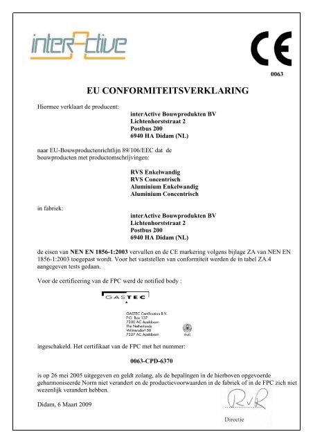
0063<br />
<strong>EU</strong> <strong>CONFORMITEITSVERKLARING</strong><br />
Hiermee verklaart de producent:<br />
<strong>interActive</strong> Bouwprodukten BV<br />
Lichtenhorststraat 2<br />
Postbus 200<br />
6940 HA Didam (NL)<br />
naar <strong>EU</strong>-Bouwproductenrichtlijn 89/106/EEC dat de<br />
bouwproducten met productomschrijvingen:<br />
RVS Enkelwandig<br />
RVS Concentrisch<br />
Aluminium Enkelwandig<br />
Aluminium Concentrisch<br />
in fabriek:<br />
<strong>interActive</strong> Bouwprodukten BV<br />
Lichtenhorststraat 2<br />
Postbus 200<br />
6940 HA Didam (NL)<br />
de eisen van NEN EN 1856-1:2003 vervullen en de CE markering volgens bijlage ZA van NEN EN<br />
1856-1:2003 toegepast wordt. Voor het vaststellen van conformiteit werden de in tabel ZA.4<br />
aangegeven tests gedaan.<br />
Voor de certificering van de FPC werd de notified body :<br />
ingeschakeld. Het certifikaat van de FPC met het nummer:<br />
0063-CPD-6370<br />
is op 26 mei 2005 uitgegeven en geldt zolang, als de bepalingen in de hierboven opgevoerde<br />
geharmoniseerde Norm niet verandert en de productievoorwaarden in de fabriek of in de FPC zich niet<br />
wezenlijk verandert hebben.<br />
Didam, 6 Maart 2009
Conformiteitsverklaring en<br />
produktinformatie<br />
„Eisen aan Metalen Rookgasafvoeren“<br />
Deel 1 Producten voor Systeemschoorstenen<br />
NEN EN 1856-1:2003<br />
Producent : <strong>interActive</strong> Bouwprodukten BV<br />
Lichtenhorststraat 2<br />
Postbus 200<br />
6940 HA Didam (NL)<br />
Productomschrijving:<br />
Notified Body:<br />
RVS Enkelwandig<br />
RVS Concentrisch<br />
Aluminium Enkelwandig<br />
Aluminium Concentrisch<br />
Gastec Certification BV<br />
Certificaatnummer / Jaar: 0063-CPD-6370 / 2005<br />
Productomschrijving van de Producten volgens EN 1856-1:2003<br />
Product omschrijving<br />
Normen nummer<br />
Temperatuur<br />
klasse<br />
Druk klasse<br />
Condensbestendig<br />
heit<br />
Corrosie<br />
weerstand<br />
Roetbrand<br />
bestendigheid<br />
Afstand tot<br />
brandbare<br />
materialen (in mm)<br />
0.1 T250/ W Vm L50045 (50)<br />
0.2 Rookgasafvoersysteem<br />
EN T200/<br />
P1<br />
W Vm L50060<br />
O<br />
(50)<br />
0.3 RVS Enkelwandig<br />
1856-1 T160 W Vm L50080<br />
(50)<br />
0.4 T250/ W Vm L50045 (0)<br />
0.5 Rookgasafvoersysteem<br />
EN T200/ W Vm L50060 (0)<br />
0.6 RVS Concentrisch<br />
1856-1 T160<br />
P1<br />
O<br />
W Vm L50080 (0)<br />
0.7<br />
D Vm L50045<br />
(0)<br />
0.8 T250/ W Vm L10/11/13/150 (50)<br />
0.9 Rookgasafvoersysteem<br />
EN T200/<br />
P1<br />
D Vm L10/11/13/080<br />
O<br />
(50)<br />
0.10 Aluminium Enkelwandig<br />
1856-1 T160 D Vm L10/11/13/100<br />
(50)<br />
0.11 T250/ W Vm L10/11/13/150 (0)<br />
0.12 Rookgasafvoersysteem<br />
EN T200/<br />
P1<br />
D Vm L10/11/13/080<br />
O<br />
(0)<br />
0.13 Aluminium Concentrisch<br />
1856-1 T160 D Vm L10/11/13/100<br />
(0)<br />
0.14 T120 W Vm L50045 (20)<br />
Rookgasafvoersysteem<br />
EN<br />
0.15 P1 W Vm L50060 O (20)<br />
RVS Enkelwandig<br />
1856-1<br />
0.16<br />
W Vm L50080<br />
(20)<br />
0.17 T120 W Vm L50045 (0)<br />
Rookgasafvoersysteem<br />
EN<br />
0.18 P1 W Vm L50060 O<br />
(0)<br />
RVS Concentrisch<br />
1856-1<br />
0.19<br />
W Vm L50080<br />
(0)<br />
Conformiteitsverklaring <strong>interActive</strong> BV blad 2 van 33
Productinformatie volgens NEN EN 1856-1 Par. 7 en bijlage ZA<br />
NR Prestatiekenmerk en eisen volgens Waarde/Klassen Bewijs / ITT Informatie<br />
NEN EN 1856-1 Par. ZA-1<br />
1.0 Nominale afmetingen Par. 4 en 5 Opgave producent Maten zie Tabel<br />
bijlage H<br />
1.1 Systeem 0.1 t/m 0.3, 0.8 t/m 0.10 60, 70, 80, 90, 100, 110 zie bijlage H<br />
en 0.14 t/m 0.16<br />
1.2 Systeem 0.4 t/m 0.7, 0.11 t/m 0.13<br />
en 0.17 t/m 0.19<br />
60-100, 70-110, 80-125,<br />
100-150<br />
zie bijlage H<br />
2.0 Materiaal Rookgaspijp:<br />
Kwaliteit:<br />
Nominale wanddikte (Minimale<br />
wanddikte)<br />
Par.: 4 en 5<br />
Par.: 6.5.2<br />
Systeem 0.1 t/m zu 0.7<br />
1.4404/1.4571<br />
Nominale wanddikte:<br />
0,45mm, 0,6mm, 0,8mm.<br />
Minimale wanddikte 0,4mm,<br />
0,54mm, 0,72mm.<br />
Opgave producent<br />
zie bijlage H<br />
Systeem 0.8 t/m zu 0.13<br />
EN AW-4047A,EN AW-<br />
1200A, EN AW-6060<br />
Nominale wanddikte: 0,8mm,<br />
1mm en 1,5mm.<br />
Minimale wanddikte:<br />
0,72mm, 0,9mm en 1,35mm.<br />
3.0 Materiaal Luchttoevoerpijp:<br />
Kwaliteit:<br />
Nominale wanddikte (Minimale<br />
wanddikte)<br />
Par.: 4 en 5<br />
Par.: 6.5.2<br />
3.1 Materiaal Außenbogen:<br />
Nominale wanddikte (Minimale<br />
wanddikte)<br />
Par.: 4 en 5<br />
Par.: 6.5.2<br />
5.0 Dichtungen<br />
Systeem 0.14 t/m zu 0.19<br />
1.4404/1.4571<br />
Nominale wanddikte:<br />
0,45mm, 0,6mm, 0,8mm.<br />
Minimale wanddikte 0,4mm,<br />
0,54mm, 0,72mm<br />
NW 100-NW150: EN 10142<br />
1.0226<br />
(DX51D+Z275-M-A-C)<br />
0,45 mm (0,4 mm)<br />
NW100-NW125: EN 10025<br />
E360 (LM2)<br />
Minimale wanddikte 1 mm<br />
NW 150: EN 10130 1.0873<br />
Minimale wanddikte 0,67<br />
5.1 Systeem 0.1 t/m 0.7 Hardheid: 65 ± 5 Shore(A)<br />
Materiaal: Siliconen<br />
Kleur: Rood<br />
Hardheid: 65 ± 5<br />
Materiaal: Viton<br />
Kleur: Groen<br />
5.2 Systeem 0.8 t/m 0.13 Hardheid: 65 ± 5 Shore(A)<br />
Materiaal: Siliconen<br />
Kleur: Rood<br />
5.3 Systeem 0.14 t/m 0.19 Hardheid: 65 ± 5 Shore(A)<br />
Materiaal: EPDM<br />
Kleur: Zwart<br />
Opgave producent<br />
Opgave producent<br />
Zulassung DiBt<br />
PZ TH Nr.: Z-7.4-3056<br />
Zulassung DiBt<br />
PZ TH Nr.: Z-7.4-3056<br />
MPA Report<br />
220004855-1<br />
Zulassung DiBt<br />
PZ TH Nr.: Z-7.2-3073<br />
MPA Report<br />
220004855-8<br />
QA Reports<br />
Zulassung DiBt<br />
PZ TH Nr.: Z-7.2-3073<br />
MPA Report<br />
220004855-10<br />
Conformiteitsverklaring <strong>interActive</strong> BV blad 3 van 33
Mechanische Festigkeit Par. 6.1<br />
8.0 Drukbelasting<br />
Par. 6.1.1.1 / 6.1.1.2<br />
9.0 Trekbelasting Par. 6.1.2 NPD<br />
10.0 Windbelasting<br />
Par. 6.1.3.2<br />
Maximale belasting<br />
enkelwandig systemen 18 m<br />
verlengpijp en concentrische<br />
systemen 10 m verlengpijp.<br />
AW systeem getest<br />
Maximale beugelafstand 2 m<br />
<strong>interActive</strong> ITT rapport:<br />
9.895.00.02 en<br />
9.895.00.42/A<br />
<strong>interActive</strong> ITT rapport:<br />
9.895.00.23<br />
Schuine installatie<br />
11.0 Maximale afwijking van het<br />
vertikale<br />
Par. 6.1.3.1<br />
12.0 Maximale lengte van de schuine<br />
installatie Par. 6.1.3.1<br />
Die maximal afwijking<br />
bedraagt 87°.<br />
Die maximale lengte van de<br />
schuine installatie is niet<br />
begrenst.<br />
<strong>interActive</strong> ITT rapport:<br />
9.895.00.04<br />
<strong>interActive</strong> ITT rapport:<br />
9.895.00.04<br />
Afstandhouder<br />
aan iedere<br />
verbinding<br />
Afstandhouder<br />
aan ieder<br />
verbinding<br />
13.1 Gasdichtheid<br />
Par. 6.3.1<br />
Lekdichtheidsklasse P 1<br />
<strong>interActive</strong> ITT rapport:<br />
9.895.00.05<br />
Gastec CRE:<br />
Reportno.: 8743<br />
<strong>interActive</strong> ITT rapport<br />
9.895.00.18<br />
<strong>interActive</strong> ITT rapport<br />
9.895.00.10<br />
13.2 Gasdichtheid<br />
Par. 6.3.1<br />
Lekdichtheidsklasse P 1<br />
InterActive ITT rapport:<br />
9.895.00.05<br />
Gastec CRE<br />
Reportno.: 8743<br />
14.1 Afstand tot brandbare<br />
materialen bij T200 en<br />
roetbrandbestendigheid<br />
Par. 6.2<br />
O (0) 5 cm, rechthoekige<br />
ommanteling moet aan twee<br />
zijden op 10 cm afstand<br />
zitten. Of er moet beluchting<br />
aangebracht zijn.<br />
Roetbrandbestendigheid NPD<br />
InterActive ITT rapport:<br />
9.895.00.05<br />
9.895.00.46<br />
Gastec CRE<br />
Reportno.: 8743<br />
15.0 Aanrakingsgevaar<br />
Par. 6.4.2<br />
17.1 Condensbestendigheid<br />
Par. 6.4.4 + 6.4.5<br />
17.2 Condensbestendigheid<br />
(Vochtbestendigheid)<br />
Par. 6.4.4 + 6.4.5<br />
18.0 Weerstand tegen het binnendringen<br />
van regenwater<br />
Par. 6.4.6<br />
Ommanteling aanbrengen<br />
behalve voor de<br />
aansluitleiding.<br />
D (niet condensbestendig)<br />
NPD<br />
NPD<br />
Opgave producent<br />
<strong>interActive</strong> ITT rapport:<br />
9.895.00.06<br />
<strong>interActive</strong> ITT rapport:<br />
9.895.00.06<br />
Stromingsweerstand<br />
19.0 Verlengpijpen<br />
Rookgasafvoersysteem<br />
Volgens EN 13384-1, R = 1<br />
mm<br />
Conformiteitsverklaring <strong>interActive</strong> BV blad 4 van 33
Par. 6.4.7.1<br />
20.0 Vormdelen Rookgasafvoersysteem<br />
Par. 6.4.7.2<br />
Volgens EN 13384-1<br />
Eisen aan Uitmondingen:<br />
21.0 Stromingsweerstand Par. 6.4.7.3 Alle uitmondingen hebben<br />
een zéta van max. 8,5 of zijn<br />
in combinatie met toestel<br />
gekeurd.<br />
Zie QA Rapporten<br />
22.0 Indringen van Regenwater<br />
Par. 6.4.8.1<br />
23.0 Aerodynamische eigenschappen<br />
Par. 6.4.8.2<br />
De constructie van de<br />
uitmondingen is in alle<br />
gevallen dusdanig dat er<br />
onder windaanval geen<br />
regenwater binnendringen<br />
kan luchtzijdig.<br />
NPD<br />
Zie QA Rapporten<br />
Zie QA Rapporten<br />
24.1 Corrosieweerstand Par. 6.5.1 Vm<br />
Verdere product informatie<br />
volgens Par. 7<br />
27.0 Veel voorkomende inbouw<br />
Opgave producent Zie bijlage H<br />
tekeningen rookgasafvoersystemen<br />
28.0 Hoe bouw je individuele<br />
Opgave producent Zie bijlage H<br />
componenten samen.<br />
29.0 Inbouw verlengpijpen Opgave producent Zie bijlage H<br />
30.0 Stromingsrichting Inbouw: Mof naar boven Opgave producent Zie bijlage H<br />
31.0 Opslag voorwaarden: Geen corrosieve omgeving Opgave producent Zie bijlage H<br />
32.0 Inbouw afdichtingen Afdichtingen in ringkamer<br />
plaatsen indien niet<br />
Opgave producent Zie bijlage H<br />
33.0 Inbouwvoorschriften voor<br />
componenten die apart geleverd<br />
worden:<br />
34.0 Minimale afstand tussen<br />
rookgasafvoer en onbrandbare<br />
schachtwand:<br />
35.0 Positie van inspectie- en<br />
reinigingsopeningen<br />
36.0 Aanbrengen van de typeplaat aan het<br />
rookgasafvoersysteem, bekleding of<br />
ommanteling:<br />
37.0 Eisen en grenzen voor de<br />
ommanteling en of omkleding:<br />
38.0 Reiniging en<br />
Reinigingsgereedschappen:<br />
39.0 Aanbevelingen tot afvoeren<br />
condenswater<br />
voorgemonteerd.<br />
Opgave producent<br />
2 cm Nationale wetgeving en<br />
normen in acht nemen<br />
De typeplaat moet aan het<br />
rookgasafvoersysteem,<br />
bekleding of ommanteling<br />
zichtbaar worden<br />
aangebracht.<br />
Geen brandbare ommanteling<br />
gebruiken<br />
Volgens nationale normen<br />
reinigen. Alleen zachte<br />
borstels gebruiken.<br />
Condensafvoer gebruiken in<br />
combinatie met een Sifon.<br />
Nationale wetgeving en<br />
normen in acht nemen<br />
Nationale wetgeving en<br />
normen in acht nemen<br />
Opgave producent<br />
Opgave producent<br />
Nationale wetgeving en<br />
normen in acht nemen<br />
Zie bijlage H<br />
Zie bijlage H<br />
Zie bijlage H<br />
Zie bijlage H<br />
Conformiteitsverklaring <strong>interActive</strong> BV blad 5 van 33
FPC Certifikaat<br />
Conformiteitsverklaring <strong>interActive</strong> BV blad 6 van 33
Annex H: Attestation of conformity <strong>interActive</strong> B.V.<br />
1. Dimensionchart and drawings.......................................Fout! Bladwijzer niet gedefinieerd.<br />
2. Drawings of common situations Flue systems..................................................................... 30<br />
3. How to build individual components together ..................................................................... 31<br />
4. Example documents ............................................................................................................. 32<br />
7
Annex H: Attestation of conformity <strong>interActive</strong> B.V.<br />
Dimensionchart products CE<br />
Dimensions<br />
System Product description Drawingnr. D1 D2 D3 D4 L1 L2 L3 L4 H1 S<br />
Extension 80 CE-001 80 82 250..2000 50 0,45<br />
Extension 100 CE-001 100 101 250..2000 50 0,45<br />
Extension 130 CE-001 130 132 1000 50 0,45<br />
Elbow 80 87° CE-007 80 82 50 110 120 93 0,8<br />
Elbow 80 45° CE-008 80 82 50 75 85 45 0,8<br />
Elbow 80 30° CE-011 80 82 50 76 91 30 0,8<br />
Elbow 80 15° CE-011 80 82 50 68 81 15 0,8<br />
Elbow 100 87° CE-014 100 102 50 125 135 93 0,8<br />
Elbow 100 45° CE-015 100 102 50 111 119 45 0,8<br />
Elbow 100 30° CE-011 100 102 50 82 95 30 0,8<br />
Elbow 100 15° CE-011 100 102 50 73 81 15 0,8<br />
Elbow 130 87° CE-014 130 132 50 184 184 93 0,45<br />
INOX excentric<br />
Elbow 130 45° CE-015 130 132 50 120 117 45 0,45<br />
Support Elbow 87° 100 CE-018 100 101 50 93 0,45<br />
Shrimped Elbow 15° 80 CE-017 80 82 50 80 80 75 0,45<br />
Shrimped Elbow 30° 80 CE-017 80 82 50 90 90 60 0,45<br />
Shrimped Elbow 45° 80 CE-017 80 82 50 112 122 45 0,45<br />
Shrimped Elbow 90° 80 CE-016 80 82 50 145 165 90 0,45<br />
Shrimped Elbow 45° 100 CE-017 100 102 50 112 136 45 0,45<br />
Shrimped Elbow 90° 100 CE-016 100 102 50 185 205 90 0,45<br />
Wall Terminal 80-80 2 pipes CE-019 80 80 660 40 0,45<br />
T-piece 80 CE-036 80 82 250 50 40 0,45<br />
T-piece 100 CE-040 100 101 242 50 60 93 0,45<br />
T-piece 130 CE-040 130 132 257 50 60 93 0,45<br />
Insp.Piece 80 CE-034 80 82 250 50 0,45<br />
Insp.Piece 100 CE-035 100 102 242 50 0,45<br />
Roof Terminal 80-80 HR CE-024 80 80 1010..1780 500..1150 295/410 0,45<br />
Roof Terminal 80-80 VR CE-025 80 80 1010..1780 500..1150 295/410 0,45<br />
Roof Terminal 100-100 CE-027 100 100 1170 713 340 0,45<br />
Roof Terminal 80-125 HR CE-022 80 125 1010..1630 500..1000 295/410 0,45<br />
Roof Terminal 80-125 VR CE-023 80 125 1010..1630 500..1000 295/410 0,45<br />
Roof Terminal 100-150 CE-026 100 150 965 370 480 0,45<br />
Wall Terminal 80-80 CE-029 80 80 800/1150 58 0,45<br />
Wall Terminal 80-125 CE-028 80 125 600/1000 58 0,45<br />
Extension 80-125 CE-002 80 125 82 127 250..2000 50 40 0,45<br />
INOX concentric<br />
Extension 80-110 CE-002 80 110 82 112 250..2000 50 40 0,45<br />
Extension 100-150 CE-002 100 150 101 152 250..2000 50 40 0,45<br />
Elbow 80-110 87° CE-009 80 110 82 112 50 110 120 93 0,8<br />
Elbow 80-110 45° CE-010 80 110 82 112 50 75 85 45 0,8<br />
Elbow 80-125 87° CE-009 80 125 82 127 50 110 120 93 0,8<br />
Elbow 80-125 45° CE-010 80 125 82 127 50 75 85 45 0,8<br />
Elbow 100-150 87° CE-012 100 150 101 152 50 125 135 93 0,8<br />
Elbow 100-150 45° CE-013 100 150 101 152 50 111 119 45 0,8<br />
T-piece 80-125 CE-037 80 125 82 127 250 50 0,45<br />
Insp.Piece 80-125 CE-032 80 125 82 127 250 50 0,44<br />
Insp.Piece 80-125 OW CE-033 80 125 82 127 250 50 0,45<br />
Extension 60 CE-001 60 62 250..6000 50 1,5<br />
Extension 70 CE-001 70 72 250..6000 50 1,5<br />
Extension 80 CE-001 80 82 250..6000 50 1,5<br />
Extension 90 CE-001 90 92 250..6000 50 1,5<br />
Extension 100 CE-001 100 102 250..6000 50 1,5<br />
Extension 110 CE-001 110 112 250..6000 50 1,5<br />
Elbow 60 87° CE-004 60 62 50 105 120 90 2<br />
Elbow 60 45° CE-003 60 62 50 71 91 45 2<br />
Elbow 70 87° CE-004 70 72 50 90 90 90 2<br />
Elbow 70 45° CE-003 70 72 50 65 65 45 2<br />
Elbow 70 30° CE-011 70 72 50 70 70 30 2<br />
Elbow 70 15° CE-011 70 72 50 65 65 15 2<br />
Elbow 80 87° CE-004 80 82 50 95 95 90 2<br />
Elbow 80 45° CE-003 80 82 50 65 70 45 2<br />
Alu excentric<br />
Elbow 80 30° CE-011 80 82 50 70 70 30 2<br />
Elbow 80 15° CE-011 80 82 50 65 65 15 2<br />
Elbow 90 87° CE-004 90 92 50 100 100 90 2<br />
Elbow 90 45° CE-003 90 92 50 70 70 45 2<br />
Elbow 100 87° CE-014 100 102 50 105 110 90 2<br />
Elbow 100 45° CE-015 100 102 50 76 78 45 2<br />
Shrimped Elbow 45° 80 CE-017 80 82 50 100 114 45 0,8<br />
Shrimped Elbow 90° 80 CE-016 80 82 50 150 160 90 0,8<br />
Shrimped Elbow 45° 100 CE-017 100 102 50 110 125 45 0,8<br />
Shrimped Elbow 90° 100 CE-016 100 102 50 170 185 90 0,8<br />
Wall Terminal 80-80 2 pipes CE-019 80 80 660 40 1,5<br />
T-piece 70 CE-039 70 72 220 50 50 1,5<br />
T-piece 80 CE-039 80 82 215 50 50 1,5<br />
T-piece 100 CE-039 100 102 235 50 50 1,5<br />
Insp.Piece 70 CE-035 70 72 350 50 1,5<br />
Insp.Piece 80 CE-035 80 82 350 50 1,5<br />
Roof Terminal 80-80 HR CE-024 80 80 1010..1780 500..1150 295/410 0,45<br />
Roof Terminal 80-80 VR CE-025 80 80 1010..1780 500..1150 295/410 0,45<br />
Roof Terminal 100-100 CE-027 100 100 1170 713 340 0,45<br />
Roof Terminal 60-100 HR CE-020 60 100 1150..1320 625..650 290..440 0,45<br />
Roof Terminal 60-100 VR CE-021 60 100 1150..1320 625..650 290..440 0,45<br />
Roof Terminal 80-125 HR CE-022 80 125 1010..1630 500..1000 295/410 0,45<br />
Roof Terminal 80-125 VR CE-023 80 125 1010..1630 500..1000 295/410 0,45<br />
Roof Terminal 100-150 CE-026 100 150 965 370 480 0,45<br />
Wall Terminal 80-80 CE-029 80 80 800/1150 58 0,45<br />
Wall Terminal 80-125 CE-028 80 125 600/1000 58 0,45<br />
Extension 60-100 CE-002 60 100 62 102 250..2000 50 40 1,5<br />
Extension 70-110 CE-002 70 110 72 112 250..2000 50 40 1,5<br />
Extension 80-125 CE-002 80 125 82 127 250..2000 50 40 1,5<br />
Extension 80-110 CE-002 80 110 82 112 250..2000 50 40 1,5<br />
Alu concentric Extension 100-150 CE-002 100 150 102 152 250..2000 50 40 1,5<br />
Elbow 60-100 87° CE-005 60 100 62 102 50 105 120 93 2<br />
Elbow 60-100 45° CE-006 60 100 62 102 50 71 91 45 2<br />
Elbow 70-110 87° CE-005 70 110 72 112 50 90 90 93 2<br />
Elbow 70-110 45° CE-006 70 110 72 112 50 65 65 45 2<br />
Elbow 80-110 87° CE-005 80 110 82 112 50 95 95 93 2<br />
Elbow 80-110 45° CE-006 80 110 82 112 50 65 70 45 2<br />
Elbow 80-125 87° CE-005 80 125 82 127 50 95 95 93 2<br />
Elbow 80-125 45° CE-006 80 125 82 127 50 65 70 45 2<br />
Elbow 100-150 87° CE-012 100 150 102 152 50 105 110 93 2<br />
Elbow 100-150 45° CE-013 100 150 102 152 50 76 78 45 2<br />
T-piece 70-110 CE-038 70 110 72 112 236 50 40 1,5<br />
T-piece 80-125 CE-038 80 125 82 127 236 50 40 1,5<br />
Insp.Piece 70-110 CE-030 70 110 72 112 255 50 1,5<br />
Insp.Piece 80-125 CE-031 80 125 82 127 300 50 1,5<br />
Accessories Support Bracket Inox CE-041 150 185-265<br />
8
Annex H: Attestation of conformity <strong>interActive</strong> B.V.<br />
9
Annex H: Attestation of conformity <strong>interActive</strong> B.V.<br />
10
Annex H: Attestation of conformity <strong>interActive</strong> B.V.<br />
11
Annex H: Attestation of conformity <strong>interActive</strong> B.V.<br />
12
Annex H: Attestation of conformity <strong>interActive</strong> B.V.<br />
13
Annex H: Attestation of conformity <strong>interActive</strong> B.V.<br />
14
Annex H: Attestation of conformity <strong>interActive</strong> B.V.<br />
15
Annex H: Attestation of conformity <strong>interActive</strong> B.V.<br />
16
Annex H: Attestation of conformity <strong>interActive</strong> B.V.<br />
17
Annex H: Attestation of conformity <strong>interActive</strong> B.V.<br />
18
Annex H: Attestation of conformity <strong>interActive</strong> B.V.<br />
19
Annex H: Attestation of conformity <strong>interActive</strong> B.V.<br />
20
Annex H: Attestation of conformity <strong>interActive</strong> B.V.<br />
21
Annex H: Attestation of conformity <strong>interActive</strong> B.V.<br />
22
Annex H: Attestation of conformity <strong>interActive</strong> B.V.<br />
23
Annex H: Attestation of conformity <strong>interActive</strong> B.V.<br />
24
Annex H: Attestation of conformity <strong>interActive</strong> B.V.<br />
25
Annex H: Attestation of conformity <strong>interActive</strong> B.V.<br />
26
Annex H: Attestation of conformity <strong>interActive</strong> B.V.<br />
27
Annex H: Attestation of conformity <strong>interActive</strong> B.V.<br />
28
Annex H: Attestation of conformity <strong>interActive</strong> B.V.<br />
29
Annex H: Attestation of conformity <strong>interActive</strong> B.V.<br />
2. Drawings of common situations Flue systems<br />
30
Annex H: Attestation of conformity <strong>interActive</strong> B.V.<br />
3. How to build individual components together<br />
The connection between two components is by means of a spigot/socket construction, see figure.<br />
When cutting the tube deburr the sawing edge to prevent the lip seal of getting damaged when connecting the<br />
components.<br />
The direction of the flue gasses is important, an upside down installed system is not allowed and will lead to<br />
system failure.<br />
When installing horizontal this should be with fall towards the boiler unless the installation instruction of the<br />
boiler says otherwise. In those cases where the boiler isn’t equipped with a integrated condensation drain a<br />
condensation drain should be installed directly above the boiler.<br />
In case of a slanted lip the seal should be positioned as shown above.<br />
31
Annex H: Attestation of conformity <strong>interActive</strong> B.V.<br />
4. Example documents<br />
32
Annex H: Attestation of conformity <strong>interActive</strong> B.V.<br />
33


