Technische Handleiding - Niko
Technische Handleiding - Niko
Technische Handleiding - Niko

Create successful ePaper yourself
Turn your PDF publications into a flip-book with our unique Google optimized e-Paper software.
330-00701<br />
READ THE COMPLETE MANUAL BEFORE ATTEMPTING INSTALLATION AND ACTIVATING THE SYSTEM.<br />
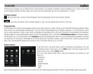
1. DESCRIPTION<br />
Deze universele modulaire dimmer, 350W, is bestemd voor DIN-railmontage en is 1TE breed. Het apparaat is<br />
geschikt voor het dimmen van resistieve, inductieve, capacitieve belastingen, dimbare led- en spaarlampen (CFLi)<br />
De dimmer functioneert zowel met het faseaansnijdings- als met het faseafsnijdingsprincipe. De keuze van het<br />
lamptype gebeurt door instellingen via de eerste 3 dipswitches onder het klapdeksel. De dimmer is voorzien van<br />
een automatische detectie en indicatie in geval van foutconditie (overbelasting, kortsluiting,…).<br />
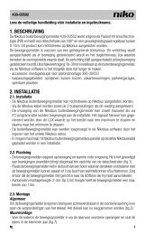
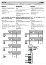
2. INSTALLATION AND CONNECTIONS<br />
To connect the load and the necessary power supply voltage, see step ➥➊.<br />
To select the correct load, see step ➥➋. To regulate the minimum level in case of incorrect light output, see<br />
step ➥➌. In this way the maximum dimming range of each lamp can be achieved. If everything is correctly<br />
connected and the power supply and the lamp are switched on, then the indication LED on the dimmer will<br />
be on; if an error has occurred, then the LED will flash. Make sure that no mixed loads are used on 1 dimmer.<br />
Installation recommendations<br />
- Preferably place the dimmers at the bottom of the distribution board.<br />
- Check the temperature. If the temperature in the distribution board rises too high (max. 35°C), provide additional<br />
ventilation. Provide sufficient space at the top of the board. Place a ventilator if necessary.<br />
3. OPERATION AND USE<br />
3.1. Normal operation<br />
The following 2 operating modes are possible: These can be selected with DIP switch 4 under the hinged cover<br />
of the dimmer. (see step ➥➊)<br />
Mode 1: 0-10V analogue<br />
When this mode is selected, the dimmer will accept a voltage control signal from 0 to 10V according to IEC standard<br />
61131-2. This mode is selected by switching DIP switch 4 ON. For the wiring diagram, see step ➥➊. From 0 to<br />
10V, lighting regulation is possible from the minimum to the maximum light intensity. The 0-10V control signals<br />
are used in professional applications, such as the <strong>Niko</strong>bus dim controller or PLC. If the input voltage lies below<br />
the threshold voltage (±1V), the connected load remains off. If the input voltage is equal to the threshold voltage,<br />
the connected load will switch on to the minimum light intensity. If the input voltage is 10V, the connected load<br />
will switch on to the maximum light intensity.<br />
Mode 2: 1-10V analogue control<br />
When this mode is selected, the dimmer operates via a current control signal from 1 to 10V according to<br />
EN60929 standard. This mode is selected by switching DIP switch 4 OFF (downward). For the wiring diagram,<br />
see step ➥➊. From 1 to 10V, lighting regulation is possible from the minimum to the maximum light intensity.<br />
The intensity of the current flowing through the control circuit determines the light level. If the input voltage lies<br />
below the threshold voltage (±1.5V), the connected load will remain off. If no control signal is connected, the<br />
connected load will switch on to the minimum light intensity. If the input voltage is 10V, the connected load will<br />
switch on to the maximum light intensity.<br />
3.2 Lamps<br />
It is possible to dim all dimmable lamps with this dimmer. (See table below.) Setting the correct load occurs by<br />
using the DIP switches under the hinged cover (see step ➥➋).<br />
Lamp<br />
HAL.230V<br />
HAL.230V<br />
HAL.12 - 24V<br />
CFLi<br />
dimmable<br />
(10 ex.)<br />
LED<br />
dimmable<br />
(10ex.)<br />
Max. 350W 350W 350W 200W 200W<br />
Min. 5W 5W 20W 5W 5W<br />
When dimming dimmable economy lamps with the memory function activated, the dim profile is set up so that<br />
the dimmer is first switched on to its maximum capacity for one second and then returns to the dimming level<br />
saved in memory. This ensures that each economy lamp, even those with memory function, can be switched on.<br />
3.3. Meaning of the red indication LED<br />
The LED turns on: - the dimmer is connected correctly (when installing)<br />
- and the load is switched on.<br />
The LED is flashing: - error condition; the dimmer is not connected correctly or there is an overload, short-circuit<br />
or an incorrect setting.<br />
4. TROUBLESHOOTING<br />
Possible causes of dimmer malfunction:<br />
- the mains voltage is not connected<br />
- the load is not connected or the connected power consumption is too high<br />
- the lamp or the cable used is defective<br />
- the thermal protection has been activated<br />
- no control signal<br />
- the minimum dimming level is set too low (for operation with memory)<br />
- a combination of the above causes<br />
The dimmer is equipped with a thermal protection. If the temperature increases excessively due to overload,<br />
switch the dimmer off. If this happens<br />
- check whether the load is too high. When doing this, keep in mind the reactive power of ferromagnetic transformers.<br />
- check the temperature in the distribution board (max. 35°C).<br />
- check whether mixed loads are being used<br />
- check whether the minimum dimming level has been set too low<br />
- check whether the correct lamp type has been selected<br />
- 10% per 5°C over the ambient temperature 35°C<br />
The dimmer can be turned on again (after cooling) by first setting the control to 0 and then switching it on again.<br />
- The indication LED keeps flashing. This indicates: - overload<br />
- overvoltage or overcurrent<br />
- short circuit<br />
5. USAGE WARNINGS<br />
- Control signals that are sent via the mains can interfere with the operation of the dimmer. (This is not a defect.)<br />
- The dimmer is never electrically separated from the mains due to the operation of the control. Therefore, all parts<br />
remain “live” even if the load (e.g., the light) is “off”.<br />
- This appliance is not suitable for controlling motors<br />
6. TECHNICAL DATA<br />
- Power supply voltage: 230V AC ±10%, frequency 50Hz<br />
- Mounting: DIN-rail (1U)<br />
- Weight: ± 70g<br />
- Allowable ambient temperature: see power consumption graph<br />
- Designed for use in an environment with a non-condensing atmospheric humidity (30% - 70%)<br />
- No-load power consumption: ±0.6W<br />
- Input impedance 0-10V: 33kΩ<br />
1-10V: 22kΩ<br />
- Maximum temperature of housing (Tc):<br />
- Maximum wire diameter per connection terminal: 2.5mm²<br />
- Power supply and load: 2 x 1.5mm² or 1 x 2.5mm²<br />
- input: 2 x 1.5mm² or 1 x 2.5mm²<br />
- Minimum load: 5W<br />
- Protections: thermal overload protection, short-circuit protection<br />
- Complies with the EN60669-2-1 standards<br />
- Wiring of analogue control:<br />
- Control circuit and power circuit of the dimmer are galvanically isolated.<br />
- The control inputs of the dimmer comply with the requirements for extra low safety voltage (SELV). If the control<br />
signals originate from appliances that also meet the SELV requirements, no specific requirements in terms of<br />
wire diameter or insulation of the control wires apply. You must keep the control wires separate from the 230V<br />
AC wires (min. 10mm). In this is not the cases, the SELV guarantees do not apply.<br />
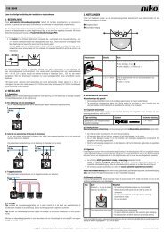
- Power consumption graph: consumption in function of the ambient temperature.<br />
Power consumption<br />
100%<br />
95%<br />
90%<br />
85%<br />
80%<br />
75%<br />
70%<br />
65%<br />
60%<br />
55%<br />
50%<br />
0 10 20 30 40 50 60<br />
Ambient temperature (°C)<br />
7. WARNINGS REGARDING INSTALLATION<br />
- The installation should be carried out by a registered installer and in compliance with the statutory regulations.<br />
- This user manual should be presented to the user. It should be included in the electrical installation file, and<br />
it should be passed on to any new owners. Additional copies are available on the <strong>Niko</strong> website or via the <strong>Niko</strong><br />
support service.<br />
- During installation, the following should be taken into account (non-exhaustive list):<br />
- the statutory laws, standards and regulations.<br />
- the technology currently available at the time of installation.<br />
- this user manual, which only states general regulations and should therefore be read within the scope of<br />
each specific installation.<br />
- the rules of proper workmanship.<br />
- In case of doubt or for the specific exchange procedure in case of a possible defect, contact the <strong>Niko</strong> support<br />
service (Belgium: +32 3 778 90 80 – United Kingdom: +44 1525 877 707) or your wholesaler. Contact<br />
details and more information can be found at www.niko.eu under the “Help and advice” section.<br />
8. GUARANTEE PROVISIONS<br />
- The period of guarantee is four years from the date of delivery. The delivery date is the invoice date of purchase<br />
of the product by the consumer. If there is no invoice, the date of production applies.<br />
- The consumer is obliged to inform <strong>Niko</strong> in writing about the non-conformity, within two months after stating<br />
the defect.<br />
- In case of a non-conformity, the consumer only has the right to a product repair or replacement free of charge,<br />
which shall be decided by <strong>Niko</strong>.<br />
- <strong>Niko</strong> shall not be held liable for a defect or damage resulting from incorrect installation, improper or careless<br />
use, incorrect operation, transformation of the product, maintenance that does not adhere to the maintenance<br />
instructions or an external cause, such as damage due to moisture or overvoltage.<br />
- The compulsory regulations of the national legislation concerning the sale of consumer goods and the protection<br />
of the consumer in the countries where <strong>Niko</strong> sells, directly or via sister companies, subsidiaries, chain<br />
stores, distributors, agents or permanent sales representatives, take priority over the above-mentioned rules<br />
and regulations.<br />
nv <strong>Niko</strong> sa Industriepark West 40, BE-9100 Sint-Niklaas, Belgium — tel. +32 3 778 90 00 — fax +32 3 777 71 20 — e-mail: support@<strong>Niko</strong>.be — www.niko.be PM330-00701R11051