SLY300 SLY500 SLY1000 SLY300E SLY500E ... - Nothnagel
SLY300 SLY500 SLY1000 SLY300E SLY500E ... - Nothnagel
SLY300 SLY500 SLY1000 SLY300E SLY500E ... - Nothnagel

Create successful ePaper yourself
Turn your PDF publications into a flip-book with our unique Google optimized e-Paper software.
INFRARED SENSOR -<br />
The infrared sensor is a safety-enhancing facility and must be used.<br />
Its installation location depends on the design of the given sliding<br />
gate. Generally speaking, the light barrier is fitted at knee height<br />
approx. 35cm above ground level. Infrared sensors comprise a<br />
transmitter element and a receiver element which have to be located<br />
opposite one another. A screwdriver can be used to open the light<br />
barrier housing (plastic). The infrared sensor is fitted to the wall with<br />
small screws and wall plugs. Usage of a single infrared sensor is a<br />
minimum requirement; we recommend using two infrared sensors<br />
(and other safety features if necessary).<br />
Should a further infrared sensor be active for the OPEN direction of<br />
travel, it has to be connected to contact 11 + 12 (stop). This is<br />
necessary if the area behind the gate has to be secured. If contact<br />
strips (accessories) are to be employed as additional safety features,<br />
they also have to be connected to the stop contact.<br />
The transmitter element needs a 2-pole cable, the receiver element a<br />
4-pole one.<br />
Cable cross-sectional area: 0.5mm2 9 9 B<br />
or more.<br />
Voltage: 12/24 volt AC/DC.<br />
Electrical connections: See control unit instructions.<br />
FLASHING LAMP -<br />
Usage of a flashing lamp is mandatory. It serves a safety-related<br />
purpose in that it warns persons in the vicinity of the gate that the<br />
given gate is moving.<br />
The flashing lamp is fixed in position using screws and wall plugs.<br />
The earthed cable has to be run up to connect with the lamp.<br />
Normally speaking, it is installed at the highest possible point<br />
(on a pillar).<br />
Cable cross-sectional area: 0.75mm2 10 10 A<br />
, 3-pole<br />
Voltage: 230 volt/AC.<br />
Electrical connections: See control unit instructions.<br />
KEY SWITCH -<br />
The key switch can be used to activate the drive as well as open and<br />
close the gate. Cable cross-sectional area: 0.5mm2 11 11 A<br />
or more.<br />
Electrical connections: See control unit instructions.<br />
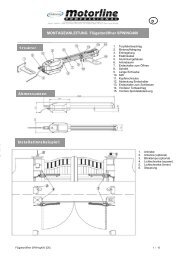
INSTALLATION OF AN EXTERNAL ANTENNA<br />
An external antenna is not a mandatory requirement. A short antenna<br />
is located on the control unit's radio adapter. Should the range of the<br />
remote control need to be extended, fit an external antenna<br />
compatible with 433 MHz (the ANT4X-1LM model incl. 750 ohm<br />
coaxial cable). It has to be connected up via the radio adapter on the<br />
control unit (see control unit instructions). The best location for an<br />
antenna is high up and as far away from electrical equipment as<br />
possible. The short cable antenna that is supplied as standard and<br />
pre-connected may then no longer be used.<br />
Electrical connections: See control unit instructions.<br />
INITIAL OPERATION<br />
Check gate functionality manually when the drive has been<br />
disengaged. Electrical operation is only possible with the control unit<br />
that is supplied as standard.<br />
Electrical connections: See control unit instructions.<br />
Always ensure that the mechanical and electrical safety requirements<br />
relevant to the given system are complied with.<br />
MAINTENANCE WORK 12<br />
The drive mechanics are maintenance-free. Check at regular<br />
intervals (monthly) that the gate hardware and the drive are all firmly<br />
in place. Disengage the drive and check gate functionality. Only an<br />
easy-running gate will work well with a drive. A drive is no substitute<br />
for a poorly functioning gate.<br />
A sliding gate can also be secured by implementing on-site<br />
measures (fence, wall, etc.). See fig. 12.<br />
TECHNICAL DATA<br />
Voltage IN<br />
Frequency<br />
Power<br />
Current rated<br />
Torque<br />
Capacitor<br />
Therminal Overload<br />
Protection<br />
Motor Speed<br />
Travel Speed<br />
Duty Cycle<br />
Working Temperatur<br />
Range<br />
Protection Class<br />
Degree of Protection<br />
Weight<br />
approx. Gate Length<br />
Max. Gate weight at<br />
max. length (incl.<br />
20% reserve)<br />
<strong>SLY300</strong><br />
230Volt<br />
50Hz<br />
300W<br />
1.3A<br />
9Nm<br />
8<br />
140<br />
1400<br />
12<br />
30<br />
-20 O C - 55 O C<br />
IP44<br />
I<br />
9<br />
5m<br />
300kg<br />
<strong>SLY500</strong><br />
230Volt<br />
50Hz<br />
360W<br />
1.5A<br />
10Nm<br />
10<br />
140<br />
1400<br />
12<br />
30<br />
-20 O C - 55 O C<br />
IP44<br />
I<br />
9<br />
8m<br />
500kg<br />
<strong>SLY1000</strong><br />
230Volt<br />
50Hz<br />
480W<br />
2.1A<br />
12Nm<br />
16<br />
140<br />
1400<br />
11.5<br />
30<br />
-20 O C - 55 O C<br />
IP44<br />
I<br />
10<br />
10m<br />
1000kg<br />
TECHNICAL DATA - CONTROL UNIT<br />
Voltage: 230V~ ±10% 50Hz<br />
Max. consumption: 10W<br />
Max. drive supply: 230V~ 50Hz 700VA max<br />
Infrared Sensor supply: 24V~ 0,5A max<br />
Working temperature: -25ºC – 55ºC<br />
Operating modes:<br />
Automatic / Semi-automatic / Step-by-step / Dead man<br />
Max. running time: 120 sec<br />
Pause period: 8 – 200sec<br />
Dimensions: 109x145mm (without box)<br />
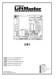
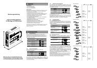
ELECTRICAL INSTALLATION<br />
The CB2 control unit is designed to be installed in a special box<br />
under the hood of the sliding gate drive and, as such, can be<br />
ordered as an accessory if not already available. The control<br />
unit can also be accommodated externally (on the wall) in a<br />
watertight box (accessory).<br />
The control unit should be the last item to be connected up, i.e.<br />
mounting the drive, laying the necessary cable and fitting light<br />
barriers (contact strips). If installation is to be performed in a<br />
permanent location, a means of disconnecting the equipment from<br />
the mains supply with a contact clearance of at least 3 mm is needed<br />
(master switch). Humidity and water will destroy the control unit.<br />
Always make sure that water, humidity and condensation cannot<br />
enter the control unit. It is vitally important that all openings and cable<br />
glands are sealed so that they are watertight.<br />
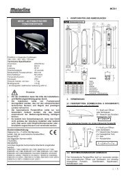
INSTALLATION OF CONTROL BOX<br />
The motor control unit is a microprocessor-controlled electronic<br />
appliance featuring state-of-the-art technology. It is equipped with all<br />
the connecting options and functions needed to guarantee safe<br />
operation. The control box incorporating the motor control unit should<br />
be installed with the cable intakes pointing downwards. It should not<br />
be continuously exposed to direct sunlight. The electronic equipment<br />
enables the pull and push forces to be set with great accuracy. If<br />
installed and set correctly, the gate can be stopped manually.<br />
When in motion, the gate can be stopped at any time by operating<br />
the remote control, the push-button or the key-operated switch.<br />
The gate must be fitted with a robust end stop for the OPEN and<br />
CLOSED positions.<br />
Generally speaking, the following minimum cable crosssectional<br />
areas must be adhered to:<br />
• 100-230Volt 1,5mm2 or more<br />
• 0-24Volt 0,5mm2 or more<br />
Tips: Bell wire is often problematic in practical use because it loses<br />
too much voltage if long lengths of wire are used.<br />
Segregate the cables in cable trunking, i.e. motor cable and light<br />
barrier cable, especially in the case of key-operated switches and ON<br />
switches (from the house wiring system) to prevent interference<br />
where long lengths of cable are used.<br />
GB-3