SLY300 SLY500 SLY1000 SLY300E SLY500E ... - Nothnagel
SLY300 SLY500 SLY1000 SLY300E SLY500E ... - Nothnagel
SLY300 SLY500 SLY1000 SLY300E SLY500E ... - Nothnagel

Create successful ePaper yourself
Turn your PDF publications into a flip-book with our unique Google optimized e-Paper software.
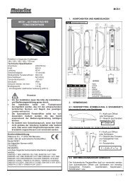
BEFORE YOU BEGIN<br />
There are many factors that are key to the choice of the right<br />
sliding gate drive. Assuming the gate is in good working order, the<br />
most difficult aspect is getting the gate to move. Once the gate is in<br />
motion, force requirements are in the main significantly reduced.<br />
• Gate size: Gate size is a very important factor. A light yet long<br />
gate (long = + 5m) needs a far greater force to set it in motion<br />
than a short, heavy gate does.<br />
WIND CAN BRAKE A GATE'S MOVEMENT OR MAKE IT HARD<br />
TO MOVE, THUS INCREASING FORCE REQUIREMENTS<br />
SIGNIFICANTLY.<br />
• Gate weight: Gate weight is only an approximate indicator the<br />
actual relevance of which can vary greatly. Example: A light gate<br />
that slides poorly is likely to need a stronger drive than a<br />
heavy, smooth-sliding gate.<br />
• Temperature: Low outdoor temperatures make it difficult or, in<br />
some cases, impossible to get the gate moving due, for instance,<br />
to changes in the ground conditions. In such cases, a stronger<br />
drive again might be necessary. High outdoor temperatures can<br />
cause the thermal protection mechanism to be activated sooner.<br />
• Operating frequency / Duty cycle: Sliding gate drives have a<br />
maximum duty cycle of approx. 30% (e.g. 30% per hour). CAUTION:<br />
The drives were not designed to be run for the maximum duty cycle<br />
on a regular basis (permanent operation). If the drive gets too hot, it<br />
switches itself off until it has cooled down to activation temperature.<br />
The outdoor temperature and the gate itself are key factors<br />
determining the drive's actual duty cycle<br />
• Safety: A sliding gate drive has to be fitted with a flashing lamp,<br />
contact strips and, if necessary, with additional light barriers as safety<br />
features. Please ensure that you comply with the standards and<br />
regulations relevant to your particular case.<br />
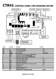
• Control unit: The control unit was developed specifically with<br />
safety aspects in mind. It is already located under the drive hood<br />
and wired up for right-hand installation as standard (motor to the<br />
right of the gate). See figs. 2 - 3.<br />
CHECK LIST - PRE-INSTALLATION WORK A - C<br />
Prior to actual installation, please check that you have been provided<br />
with all the parts indicated within the scope of supply.<br />
Make sure your gate system is in good working order.<br />
The gate must run smoothly, not jerkily and not make contact with<br />
the ground at any point. Bear in mind that the ground can be several<br />
centimetres higher in winter. The gate needs to be stable with as little<br />
play as possible to prevent any lateral movement from occurring. The<br />
easier the gate moves, the more sensitive the force setting needs to<br />
be.<br />
Make a note of the materials you still need and make sure you obtain<br />
them prior to installation - adhesive anchors (strong plugs), screws,<br />
stops, cable, distributor boxes, tools, etc.<br />
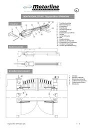
OVERVIEW OF INSTALLATION<br />
A general overview of installation can be found on the front sheet of<br />
these instructions. The drive has to be installed behind the wall to<br />
ensure that no part of it projects out into the gate opening. The motor<br />
has to be mounted on the flush fitted base plate. The rack bar shown<br />
has to be fitted to the gate with the fixing material supplied.<br />
Decide which is the best height for fixing the rack bar to the gate and<br />
use this to determine the installation dimensions for the motor unit<br />
and base plate. Should the gate be unsuitable for fitting the rack bar<br />
to it, a fixing profile (angle bracket, shaped tubing, etc.) needs to be<br />
mounted first.<br />
INSTALLATION OF DRIVE BASE PLATE 5 - 6 A<br />
The base plate for the drive can either be concreted in or, if appropriate,<br />
welded into position. The place where the base plate is usually located<br />
is shown on the installation overview. The concrete plinth needs to be of<br />
an appropriate size (approx. 50cm x 50cm x 50cm).<br />
Please note: If it is impossible to precisely determine the height of<br />
the plinth and the distance from the gate prior to installation, it is<br />
advisable to mount the rack bars first and then concrete in the base<br />
plate. Spacers are fitted to move the rack bars approx. 40mm<br />
towards the inside.<br />
The distance from the bottom edge of the rack bar to the base plate<br />
is approx. 8 - 9cm. The base plate permits final height and depth<br />
adjustments of several centimetres to be made, but you are advised<br />
to work as precisely as possible from the outset.<br />
MOUNTING MOTOR AND GEAR UNIT<br />
The drive should be fitted on to the threaded bolts in the base plate.<br />
The height should be set such that there is a gap of approx. 1 - 2mm<br />
between the cog wheel and the rack bar. The weight of the gate should<br />
not be borne by the cog wheel! Position the drive via the adjustment<br />
holes such that its location vis-à-vis the rack bar complies with the<br />
installation dimensions.<br />
MOUNTING RACK BAR 4<br />
The easiest way to fit the rack bar is to first place it on the motor's<br />
drive cog, disengage the motor and, by pushing the gate further with<br />
the rack bar, screwing the bar bit by bit firmly in position. In this way,<br />
you ensure that the rail bar engages with the cog wheel in an optimum<br />
manner. While doing this, do not forget to mark each fixing point.<br />
DRIVE RELEASE MECHANISM (MANUAL OPERATION) 7<br />
The drive is equipped with a lockable release mechanism to enable<br />
the gate to be operated manually in a power cut. The release<br />
mechanism is shown in fig. 7 with the clutch disengaging the link<br />
between the cog wheel and the gear.<br />
To release the drive: Position the socket spanner appropriately and<br />
turn it 180 degrees. Then turn the release lever 180 degrees too.<br />
Finished.<br />
FITTING LIMIT SWITCHES (TO GATE) 8<br />
The limit switches are assembled as shown in fig. 8.<br />
One limit switch magnet is designated A (1) and the other B (2).<br />
Fit the limit switches on to the rack bar in those places where the<br />
final travel positions are roughly expected to be. The magnet should<br />
point towards the motor. The switch (contact) is located in the middle<br />
of the motor. Screw the retaining clip only provisionally in place or<br />
slot it lightly on to the rack bar.<br />
Limit switch A (1) for gate closed; limit switch B (2) for gate<br />
open.<br />
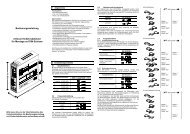
TESTING LIMIT SWITCH FUNCTIONALITY (LIFTMASTER<br />
CONTROL)<br />
Disengage the gate and operate it only using your hands. Push the<br />
gate into the respective final travel positions. The control unit should<br />
already have been connected up.<br />
On the control unit there are two red LEDs (LED 5 & LED 6) that go<br />
out when the magnet on the gate trips the given switch. One LED is<br />
for limit switch OPEN (LED 5) and the other for CLOSED (LED 6).<br />
When you open the gate manually, the correct LED should go out. If<br />
the wrong LED goes out, you need to swap limit switches A (1) and<br />
B (2) around. Alternatively, the limit switch cables connected to the<br />
control unit (17 + 19) can be swapped around. The distance between<br />
the limit switch magnet and the switch on the drive should be as<br />
small as possible. Under no circumstances should it be more than<br />
25mm.<br />
Important: If the limit switches have been swapped around, the gate<br />
will open and not close after the set pause when in programme<br />
selection (automatic) mode!<br />
Caution: A sliding gate must run in a guide rail and should not<br />
be able to leave the rail. This means end stops need to be fitted<br />
for both directions!<br />
GB-2