SLY300 SLY500 SLY1000 SLY300E SLY500E ... - Nothnagel
SLY300 SLY500 SLY1000 SLY300E SLY500E ... - Nothnagel
SLY300 SLY500 SLY1000 SLY300E SLY500E ... - Nothnagel

Create successful ePaper yourself
Turn your PDF publications into a flip-book with our unique Google optimized e-Paper software.
Contents: General Information on<br />
Installation and Use:<br />
Details of Contents: Page 1<br />
Before You Begin: Page 2<br />
Check List: Page 2, figs. A - C<br />
Overview of Installation: Page 2, fig.<br />
Installation of Rack Bar:<br />
Page 2, fig. 4<br />
Electrical Installation: figs. 2 - 3<br />
Installation of Base Plate: Page 2<br />
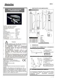
Contents in <strong>SLY300</strong>, <strong>SLY500</strong>, <strong>SLY1000</strong> packs<br />
(1) Drive motor (1x)<br />
(2) Capacitor (pre-installed) (1x)<br />
(3) Limit switch A or (1) (1x)<br />
(4) Limit switch B or (2) (1x)<br />
(5) Base plate for drive motor (1x)<br />
(6) Accessories bag<br />
Additionally for models: <strong>SLY300</strong>E, <strong>SLY500</strong>E, <strong>SLY1000</strong>E<br />
(7) Control unit with housing (pre-installed as standard<br />
for right-hand installation) (1x)<br />
1<br />
Mounting Drive on Base Plate:<br />
Page 2, figs. 5 + 6 - 6 A<br />
Drive Release Mechanism:<br />
Page 2, fig. 7<br />
Limit Switches: Page 2, fig. 8<br />
Light Barrier:<br />
Page 3, figs. 9 - 9 B<br />
Flashing Lamp: Page 3, figs. 10 - 10 A<br />
External Antenna:<br />
Page 3, figs. 11 - 11 A<br />
Initial Operation: Page 3<br />
Maintenance Work: Page 3, figs. 12<br />
Typical System Set-up:<br />
Page 4<br />
Teaching in Remote Control:<br />
Page 5, fig. 13<br />
Technical Data: Page 3<br />
CE Conformity Certificate: Page 4<br />
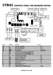
Additionally for models: <strong>SLY300</strong>K, <strong>SLY500</strong>K, <strong>SLY1000</strong>K<br />
(8) Flashing lamp (1x)<br />
(9) Light barrier (pair)<br />
(10) Radio receiver (pre-installed) (1x)<br />
(11) Handset 433MHz (2x)<br />
(12) Key-operated aerial (1x)<br />
(13) External Antenna (1x)<br />
READ THESE IMPORTANT SAFETY INSTRUCTIONS BEFORE STARTING WORK<br />
This symbol means 'Caution!'; it is a sign that compliance with the given instruction is required as non-compliance can lead to<br />
persons being injured and property damaged. Please read such warnings carefully.<br />
This gate drive has been designed in such a way and tested to ensure that it offers adequate safety providing its installation<br />
and use exactly comply with the following safety instructions.<br />
Non-compliance with the following safety instructions can lead to persons being seriously injured or property badly damaged.<br />
Take great care when working with tools and<br />
hardware. Never wear rings, watches or loose clothing<br />
when you are performing installation or repair work on<br />
the gate.<br />
Electric cables should be laid in accordance with local<br />
building and installation regulations and may only be<br />
connected to a properly earthed mains supply by a<br />
qualified electrician.<br />
When installing the drive, sufficient clearance must be left<br />
between the item driven and the surrounding parts of the given<br />
building (e.g. a wall) due to the opening movement of the item<br />
driven.<br />
Please remove all locks fitted to the gate in order to avoid<br />
damaging the gate.<br />
Once installation has been completed, you must check<br />
that the mechanism is correctly adjusted and that the<br />
drive, safety system and emergency release all<br />
function as they should.<br />
If the gate system is fitted with a slip-gate, the drive<br />
may not be started or move further until the slip-gate<br />
has been closed properly.<br />
CAUTION! Only use the drive if you have a clear view of<br />
the gate, if there are no obstacles in the gate's path and<br />
the drive is correctly adjusted. Children should not be<br />
playing near the gate when the drive is to be used.<br />
It is important to keep the gate in good working order.<br />
Gates that do not open and close smoothly and fully<br />
should be repaired without delay. Do not try to repair<br />
the gate yourself. Have it done by a person qualified.<br />
Keep any extra items of equipment and accessories out of<br />
the reach of children. Do not allow children to operate the<br />
push-buttons or remote control. Serious injuries can be<br />
caused by a gate that is closing.<br />
Automatically controlled equipment must be<br />
disconnected from the mains when maintenance work<br />
e.g. cleaning is being performed.<br />
In the case of a permanently laid installation, an<br />
isolating device must be fitted to ensure that all the<br />
connections can be isolated via a switch (min. 3mm<br />
contact opening clearance) or a separate fuse.<br />
Make sure that the persons installing, servicing or using<br />
the drive observe these instructions. Keep the<br />
instructions in a safe yet readily accessible place.<br />
Once the drive has been installed, the gate must be<br />
tested to ensure that there is no risk of persons trapping<br />
or cutting themselves.<br />
Disconnect the gate drive from the power supply before<br />
any repairs are made.<br />
The sliding gate drive can be activated via push-buttons, key-operated switches, keyless switches (radio) or remote control; once the<br />
drive has been disengaged with the appropriate key, the gate can be opened by hand. The sequence of functions initiated by a<br />
command issued via a remote control, push-button, etc. depends on how the control's electronic system has been set.<br />
GB-1