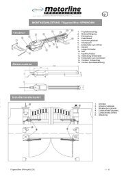
Anleitungen Steuerelektronik Instructions Commande ... - Nothnagel
Anleitungen Steuerelektronik Instructions Commande ... - Nothnagel
Anleitungen Steuerelektronik Instructions Commande ... - Nothnagel

Create successful ePaper yourself
Turn your PDF publications into a flip-book with our unique Google optimized e-Paper software.
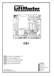
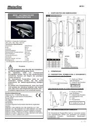
INITIAL OPERATION AND TRANSFER<br />
• Connect up the control unit including the safety inputs<br />
• Connect up the gate and lock the motors<br />
• Connect the control unit to the mains<br />
• Check whether any of the LEDs of the safety module have<br />
lit up; this indicates that the control unit has been blocked<br />
because one of the safety devices has been triggered<br />
• Have the limit switches been jumpered? (This should be<br />
done in the factory for 14A and 15A, and for 14B and 15B.)<br />
• Using a screwdriver, adjust the force of potentiometers M1<br />
and M2 (middle left) initially to about 30-50%, depending on<br />
the size and weight of the gate<br />
• Adjust potentiometer P1 to 50% (time adjustment).<br />
• Set potentiometers P2 and P3 to left-hand stop<br />
• Are the end stops in the Open and Closed directions fixed<br />
(present).<br />
• Now push the test button on the control unit; both doors of<br />
the gate should open<br />
• If only one door opens, the other must have been<br />
connected up wrongly.<br />
• Make any fine adjustments that may be necessary<br />
• Check the operation of all safety devices<br />
• Connect the receiver, and “teach” the transmitter how to<br />
work with the system.<br />
• Instruct the personnel who will be operating the system<br />
• Complete the transfer form<br />
INITIAL SETTING OF REMOTE CONTROL 7<br />
The PTT-approved, charge-free radio remote control unit<br />
functions with a computer pre-programmed private<br />
security code (approximately 3.5 billion code<br />
possibilities). In this way, your swing gate control unit can<br />
only be activated by handset with the correct code. The<br />
operating range depends on local conditions.<br />
The receiver module of the motor control unit has a built-in<br />
self-learn function. It can be set in accordance with the preprogrammed<br />
code of the handset by pressing the learn<br />
button (Illustration 7).<br />
The control unit comprises 2 learn channels. In this way, the<br />
handset may be used to open or close one gate only or both<br />
gates simultaneously. When, for example, channel 1 (1)<br />
receives the remote control code of the first control button of<br />
the handset, then only one gate is opened. When the second<br />
channel (2) is set in accordance with the remote control code<br />
of the second control button, then both gates are operated<br />
when this button is pressed.<br />
In order to configure the control PCB pre-programmed code in<br />
accordance with the handset, the learn and transmit buttons<br />
for the required channel must be pressed and held until the<br />
associated LED lights up briefly. When a multi-control handset<br />
is used, this procedure must be repeated for each control<br />
button and associated learn channel.<br />
Repeat this procedure for every transmitter.<br />
ANTENNE: An antenna is connected to the radio reception<br />
module. If a longer range is required, connect an external<br />
antenna (ANT4X-1LM) (Illustration 7).<br />
709112B-GB<br />
DELETION OF PROGRAMMED<br />
REMOTE-CONTROL CODES<br />
Press the corresponding learn button (1 or 2) approx. 10 sec.<br />
on the receiver PCB until the learn LED goes off. The code<br />
memorised with this learn button has now been deleted.<br />
REPROGRAMMING<br />
When reprogramming, the above-mentioned coding steps must<br />
be repeated for all remote-control handsets in operation and<br />
their control buttons. The operating range of the remote-control<br />
unit depends on local conditions. Press and hold the button on<br />
the handset (approx. 2 seconds) until the gate begins to move.<br />
In the PTT-approved frequency range for the radio control of<br />
gates, there are also medical, industrial, scientific, military and<br />
household radio systems in operation, some of which have a<br />
very high transmission range. The close proximity of such a<br />
radio installation could lead to a reduction in operating range or<br />
temporary interference in your radio remote-control system.<br />
ACCESSORIES & REPLACEMENT PARTS 8<br />
27MHz 418MHz 433MHz<br />
(1) Models 750E 4180E 4330E 1-Function Remote Control<br />
(2) Model 751E 1-Function Remote<br />
Control with Dipswitch<br />
(3) Models 752E 4182E 4332E 2-Function Remote Control<br />
(4) Models 4183E 4333E 3-Function Remote Control<br />
(5) Model 754E 4-Function Remote Control<br />
(6) Models 4180E 4335E 3-Functionl Mini-Remote<br />
Control<br />
(7) Models 727E 787E 747E Wireless keyless entry<br />
(8) Models 801245 801221<br />
801238, 801504 Module<br />
(9) Model 704090 Accessory package incl.<br />
Capacitor<br />
(10) Model WGO300L/WGO400L Motor left hand<br />
Model WGO300R/WGO400R Motor right hand<br />
(11) Model 100263E/770E Infrared Sensor<br />
(12) Model 100027 1-Function Keyswitch<br />
(Flush mount - 100010)<br />
Model 100041 2-Function Keyswitch<br />
(Flush Mount - 100034)<br />
(13) Model 801337 Adapter<br />
(14) Model 760E Outside Keylock<br />
(15) Model FLA230-2 Flashing Light Kit<br />
(16) Model 801689 Module for 770E<br />
(Infrared Sensor)<br />
(17) Model 801696 Module for 100263E<br />
(Infrared Sensor)<br />
(18) Model 16200LM Door in door switch<br />
(15) Model ANT4X-1LM Antenna Extension Kit<br />
GB-4