Anleitungen Steuerelektronik Instructions Commande ... - Nothnagel
Anleitungen Steuerelektronik Instructions Commande ... - Nothnagel
Anleitungen Steuerelektronik Instructions Commande ... - Nothnagel

You also want an ePaper? Increase the reach of your titles
YUMPU automatically turns print PDFs into web optimized ePapers that Google loves.
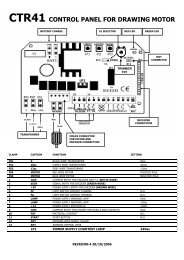
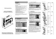
ELECTRONIC CONTROL WITH CONNECTIONS 1<br />
ELEKTRICAL INSTALLATION 2<br />
The electronic control unit supplied is required for operation<br />
of the wing gate actuator. This control unit comprises an<br />
electronic microprocessor-control system employing the latest<br />
technology. It may be used for the connection of 1 or 2<br />
motors and offers all connection possibilities and functions<br />
necessary for safe and reliable operation.<br />
The electrical connections for single- or double gates are<br />
given in Illustration 2.<br />
The control box containing the motor control module is to be<br />
fitted with cable entry at bottom. It should not be continuously<br />
exposed to direct sunlight. For weather protection, we<br />
recommend the fitting of a small protection roof.<br />
Thanks to the electronic control unit, fine adjustment of the<br />
push-pull torque is possible. When correctly adjusted, gate<br />
movement can be easily blocked by hand.<br />
For the OPEN and CLOSED positions, the gate requires a<br />
stable end stop as the swing gate actuator unit is not<br />
fitted with limit switches and the electronic controls are<br />
switched off by time.<br />
CONNECTION OVERVIEW<br />
The control unit should be connected up last, i.e. after the<br />
motor has been mounted, the necessary cables laid and the<br />
Infrared Sensors or contact strips fixed in place.<br />
In the case of permanent mounting, means of separating the<br />
system from the mains must be provided. The contact<br />
spacing of the main switch used in this connection must be at<br />
least 3 mm.<br />
NOTE:<br />
In these instructions, relay contacts are designated as<br />
NC (normally closed) and NO (normally open).<br />
• NC contacts are closed, and open when actuated<br />
• NO contacts are open, and close when actuated<br />
OVERVIEW<br />
TERMINAL<br />
PE<br />
PE<br />
PE<br />
C1<br />
1<br />
2<br />
3<br />
C1<br />
C2<br />
4<br />
5<br />
6<br />
C2<br />
7<br />
8<br />
9<br />
10<br />
11A<br />
12A<br />
13A<br />
14A<br />
15A<br />
16A<br />
17A<br />
11B<br />
12B<br />
13B<br />
14B<br />
15B<br />
16B<br />
17B<br />
DESCRIPTION<br />
Earth supply cord<br />
Earth motor 1<br />
Earth motor 2<br />
Capacitor motor1<br />
Direction CLOSED (L1.1) motor 1<br />
MP<br />
Direction OPEN (L1.2) motor 1<br />
Capacitor motor 1<br />
Capacitor motor 2<br />
Direction CLOSED (L1.1) motor 2<br />
MP<br />
Direction OPEN (L1.2) motor 2<br />
Capacitor motor 2<br />
Flashing light MP 230Volt ˜<br />
Flashing light L1 230Volt ˜<br />
E-lock drive NO<br />
E-lock drive NO<br />
Safety input OV (socket module 1)<br />
Safety input +24V (socket module 1)<br />
Switching input 1 (socket module 1)<br />
Limit switch contact 1 (factory bridged)<br />
Limit switch contact 1 (factory bridged)<br />
Push button motor 1 only, NO<br />
Push button motor 1 only, NO<br />
Safety input 0V (socket module 2)<br />
Safety input +24V (socket module 2)<br />
Switching input 2 (socket module 2)<br />
Limit switch contact 2 (factory bridged)<br />
Limit switch contact 2 (factory bridged)<br />
Push button motor 1 + 2 NO<br />
Push button motor 1 + 2 NO<br />
GB-2