Instruction Sheet Swing Cylinders — Metric 2,2 and 5,6 kN - Enerpac
Instruction Sheet Swing Cylinders — Metric 2,2 and 5,6 kN - Enerpac
Instruction Sheet Swing Cylinders — Metric 2,2 and 5,6 kN - Enerpac

Create successful ePaper yourself
Turn your PDF publications into a flip-book with our unique Google optimized e-Paper software.
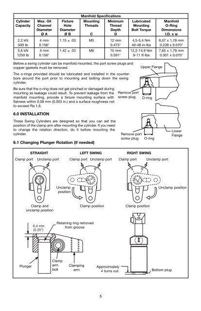
Manifold Specifications<br />
Cylinder Max. Oil Fixture Mounting Minimum Lubricated Manifold<br />
Capacity Channel Hole Threads Thread Mounting O-Ring<br />
Diameter Diameter Depth Bolt Torque Dimensions<br />
Ø A Ø B C D I.D. x w<br />
2,2 <strong>kN</strong> 4 mm 1.15 ± .03 M5 12 mm 4,5-5,4 Nm 6,07 x 1,78 mm<br />
500 lb 0.156" 0.473" 40-48 in-lbs 0.239 x 0.070"<br />
5,6 <strong>kN</strong> 4 mm 1.42 ± .03 M6 15 mm 12,2-14,9 Nm 7,65 x 1,78 mm<br />
1250 lb 0.156" 0.591" 9-11 ft-lbs 0.301 x 0.070"<br />
Before a swing cylinder can be manifold mounted, the port screw plugs <strong>and</strong><br />
copper gaskets must be removed.<br />
The o-rings provided should be lubricated <strong>and</strong> installed in the counterbore<br />
around the port prior to mounting <strong>and</strong> bolting down the swing<br />
cylinder.<br />
Be sure that the o-ring does not get pinched or damaged during<br />
mounting as leakage could result. To prevent leakage from the<br />
manifold mounting, provide a fixture mounting surface with<br />
flatness within 0,08 mm (0.003 in.) <strong>and</strong> a surface roughness not<br />
to exceed Ra 1,6.<br />
6.0 INSTALLATION<br />
These <strong>Swing</strong> <strong>Cylinders</strong> are designed so that you can set the<br />
position of the clamp arm after mounting the cylinder. If you need<br />
to change the rotation direction, do it before mounting the<br />
cylinder.<br />
6.1 Changing Plunger Rotation (if needed)<br />
Clamp port Unclamp port Clamp port Unclamp port<br />
A<br />
R<br />
L<br />
S<br />
B<br />
Clamp <strong>and</strong><br />
unclamp position<br />
Plunger<br />
STRAIGHT LEFT SWING RIGHT SWING<br />
.25 "<br />
6,4 mm<br />
(6,4mm) (0.25")<br />
Unclamp<br />
position<br />
A<br />
S<br />
R<br />
L<br />
B<br />
Clamp position<br />
Retaining ring removed<br />
from groove.<br />
Clamp<br />
arm<br />
bolt<br />
Clamping<br />
arm<br />
Approximately<br />
4 turns out.<br />
5<br />
Clamp port<br />
A<br />
L<br />
S<br />
R<br />
B<br />
Clamp position<br />
Upper Flange<br />
Remove port<br />
screw plug. O-ring<br />
Remove port<br />
screw plug.<br />
O-ring<br />
Unclamp port<br />
Unclamp position<br />
Bottom plug<br />
Lower<br />
Flange