Instruction Sheet Swing Cylinders — Metric 2,2 and 5,6 kN - Enerpac
Instruction Sheet Swing Cylinders — Metric 2,2 and 5,6 kN - Enerpac
Instruction Sheet Swing Cylinders — Metric 2,2 and 5,6 kN - Enerpac

Create successful ePaper yourself
Turn your PDF publications into a flip-book with our unique Google optimized e-Paper software.
WARNING: Only use hydraulic cylinders in a coupled system. Never use a cylinder with unconnected<br />
couplers. If the cylinder becomes extremely overloaded, components can fail catastrophically causing<br />
severe personal injury.<br />
IMPORTANT: Hydraulic equipment must only be serviced by a qualified hydraulic technician. For<br />
repair service, contact the Authorized ENERPAC Service Center in your area. To protect your warranty,<br />
use only ENERPAC oil.<br />
WARNING: Immediately replace worn or damaged parts by genuine ENERPAC parts. St<strong>and</strong>ard grade<br />
parts will break causing personal injury <strong>and</strong> property damage. ENERPAC parts are designed to fit<br />
properly <strong>and</strong> withst<strong>and</strong> high loads.<br />
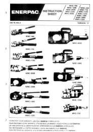
3.0 DESCRIPTION<br />
These swing cylinders are designed to swing 90° in a clockwise or counter-clockwise direction. They can also<br />
be used in straight clamping applications. Single-acting <strong>and</strong> double-acting swing cylinders are available.<br />
Clamp arms are not supplied with cylinders. Clamp arms can be purchased separately or made according to<br />
the specifications on page 13.<br />
Model Number Code<br />
1 2 3 4 5 6 Optional<br />
S = swing T = threaded body R = right swing S = single-acting 2 = 2,2 <strong>kN</strong> 2 = metric V = Viton<br />
cylinder U = upper flange L = left swing D = double-acting 5 = 5,6 <strong>kN</strong><br />
L = lower flange S = straight<br />
(no swing)<br />
4.0 PRELIMINARY INFORMATION<br />
IMPORTANT: Failure to read <strong>and</strong> follow these instructions may lead to system malfunction or product<br />
failure, <strong>and</strong> could invalidate your warranty.<br />
(1) High flow rates can lead to excessive cylinder speed which can cause cylinder damage. Hydraulic<br />
pressure <strong>and</strong> cylinder speed must be adjusted to match the length of clamp arm. The clamping force<br />
also varies with the length of the clamp arm. Refer to page 2 for operating specifications.<br />
(2) Flow controls with return checks should be used to reduce swing cylinder speed to the<br />
recommended rate. The return checks help minimize back pressure that could lead to an unclamp<br />
malfunction on single-acting systems.<br />
(3) When using single-acting swing cylinders, limit the return flow back pressure to 3,5 bar (50 psi)<br />
maximum. Large diameter tubing (10 mm O.D. or larger) <strong>and</strong> flow controls with free flow return<br />
checks help minimize back pressure. Consult <strong>Enerpac</strong> for proper system design.<br />
(4) Excessive return flow back pressure can also damage double-acting swing cylinders. Limit the<br />
return flow back pressure to 42 bar (600 psi) maximum. Double-acting systems should be set up for<br />
a metered-in with reverse free flow in the clamp port.<br />
(5) Clamping of the part should occur at the midpoint of the vertical travel. No clamping of part shall occur<br />
while the swing clamp is turning. Clamp arm should freely travel during the 90° rotation (avoid contact<br />
with cutter heads, tools, etc.).<br />
(6) Attaching clamp arm to cylinder plunger must be done according to the instructions on page 6.<br />
2