You also want an ePaper? Increase the reach of your titles
YUMPU automatically turns print PDFs into web optimized ePapers that Google loves.
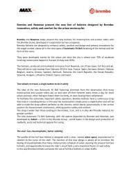
High Performance Brake Systems<br />
Release<br />
n. 01/2010<br />
3
Speed<br />
SECTION<br />
19
Adjustable (RCS) Radial Master Cylinder<br />
The RCS device consists into an eccentric drive<br />
that allows to select the pump lever ratio<br />
between 18 and 20 mm, to obtain the ideal<br />
feeling among the rider, his driving style, the<br />
bike and the course: simply selecting the lever<br />
ratio, it is now possible to have a more reactive<br />
system (20 mm) or a more adjustable one<br />
(18 mm).* Today the RCS brake master cylinder is<br />
available in two versions: 19 or 15.<br />
These numbers indicate the piston diameter and<br />
define the application of the master<br />
cylinders: 19RCS for double discs systems with<br />
axial or radial four pistons calipers<br />
(NON floating), 15RCS for single disc systems<br />
(SuperMoto) or dual floating two pistons<br />
calipers (4 pistons in total).<br />
The RCS range also includes two versions of<br />
clutch master cyclinders: 19 or 16. In the first<br />
case, the ratio can be changed between 18 and<br />
20, in the second between 18 and 16.<br />
Technical Info • Scheda descrittiva<br />
Moto GP Piston<br />
Piston, seals and push rod are the same as those<br />
used in the official MotoGP and SBK master<br />
cylinders: very narrow tolerances for the highest<br />
precision while braking.<br />
Body<br />
Produced in forged aluminium alloy,<br />
is partially CNC machined and then finished by<br />
hard anodizing process.<br />
Lever<br />
It is made by two main components: the lever<br />
drive and the “half” folding lever, both<br />
produced in forged aluminium with black finishing.<br />
Micro-Switch for Rear Brake Light<br />
For road use of the 19RCS M/C, the body has a<br />
dedicated housing for a rear light micro-switch,<br />
included in the box.<br />
*20 mm.<br />
Black spot<br />
Il sistema RCS consiste in un registro col quale è<br />
possibile modificare l’interasse leva su 18<br />
oppure 20 mm, in modo da raggiungere il<br />
feeling ideale tra pilota e moto: variando<br />
l’interasse, infatti, è possibile rendere l’impianto<br />
frenante più reattivo e pronto (int. 20) oppure<br />
più modulabile (int. 18).*<br />
La pompa radiale RCS è disponibile in due<br />
versioni: 19 oppure 15. Questi numeri<br />
identificano il diametro del pistoncino e<br />
determinano il loro utilizzo: la 19RCS deve<br />
essere impiegata su impianti bidisco 4 pistoncini<br />
ma NON flottanti, mentre la 15 RCS può essere<br />
montata su impianti monodisco con pinza a 4<br />
pistoncini oppure bidisco ma con pinze di tipo<br />
flottante.<br />
Nella gamma RCS sono presenti anche le<br />
frizioni, con pistoncino ø 19 o ø 16. Nel primo<br />
caso la variazione d’interasse è stabilita in<br />
18 – 20 mm, mentre nel tra 16 e 18 mm.<br />
Pompante interno MOTO GP<br />
Il pistoncino, le guarnizioni ed il puntalino della<br />
19 RCS sono i medesimi delle pompe utilizzate<br />
dalla quasi totalità dei piloti della MotoGP e<br />
della SB. Ridottissime tolleranze di lavorazione e<br />
ottima scorrevolezza.<br />
Corpo Pompa<br />
Il corpo pompa è in lega d’alluminio, ottenuto<br />
tramite forgiatura e lavorato successivamente<br />
CNC con fresature d’alleggerimento.<br />
Per la finitura superficiale è stata scelta<br />
l’ossidazione dura.<br />
Leva<br />
La leva è costituita da due componenti<br />
principali: il guida Leva Racing e la leva stessa,<br />
snodata, realizzata attraverso forgiatura.<br />
Interruttore Luce Stop (freno)<br />
E’ stato predisposto un alloggiamento specifico<br />
per l’interruttore meccanico di accensione luce<br />
stop, per l’utilizzo stradale della pompa freno.<br />
*18 mm.<br />
Red spot<br />
37<br />
1
1<br />
38<br />
Radial RCS Brake M/C<br />
Code 110A26310 (19 RCS)<br />
Code 110A26320<br />
Code 110A26330<br />
Technical Characteristics • Caratteristiche Tecniche<br />
Pistons / Pistoni Ø 19 - 15 mm.<br />
Distance center to center / Interesse leva 18 / 20 mm. (adjustable)<br />
Construction Material / Materiale CNC Forged Aluminium / Alluminio Forgiato CNC<br />
Finishing / Finissaggio Hard anodizing / Anodizzazione dura<br />
Weight / Massa 350 gr.<br />
Brake Fluid / Fluido freni DOT 4<br />
Spare Parts • Ricambi<br />
(15 RCS<br />
Short Lever)<br />
(15 RCS<br />
Long Lever)<br />
Lever (complete) for 19 RCS / Leva completa per 19 RCS<br />
110A26399<br />
Half lever for 19 RCS / Terminale leva per 19 RCS<br />
110A26398<br />
Half lever for 15 RCS / Terminale leva per 15 RCS<br />
110A26396<br />
Handlebar clamp / Cavallotto<br />
110A26388<br />
Bleeding screw / Vite spurgo<br />
05338763<br />
Lever pivot / Perno leva<br />
110459291<br />
Oil reservoir connection / Raccordo serbatoio<br />
10312720<br />
Micro-switch / Micro interruttore<br />
110467195<br />
Lever adj. / Regolazione leva<br />
10510730<br />
Rubber cup and sticker (flag) /<br />
Tappo in gomma e adesivo (bandierina)<br />
110A26389
RCS<br />
Master Cylinder<br />
Accessories<br />
RCS Accessories • Accessori RCS<br />
“Low drag” brake lever / Leva freno con intaglio<br />
110A26378<br />
“Low drag” clutch lever / Leva frizione con intaglio<br />
110A26379<br />
Right clamp with M8x1,25 mirror fitting /<br />
Cavallotto destro porta specchio M8x1,25<br />
110A26380<br />
Left clamp M8x1,25 / Cavallotto sinistro M8x1,25<br />
110A26381<br />
Remote adjuster / Regolatore a distanza<br />
110A26384<br />
Brake reservoir kit / Kit serbatoio freno<br />
110A26385<br />
Clutch reservoir kit / Kit serbatoio frizione<br />
110A26386<br />
CNC Clamp (red logo) / Cavallotto CNC (logo rosso)<br />
110A26387<br />
CNC Clamp (std. logo) / Cavallotto CNC (logo std.)<br />
110A26388<br />
Right clamp with M10x1,25 mirror fitting /<br />
Cavallotto destro porta specchio M10x1,25<br />
110A26390<br />
Left clamp M10x1,25 / Cavallotto sinistro M10x1,25<br />
110A26391<br />
39<br />
1
1<br />
40<br />
Radial Master<br />
Cylinder<br />
Technical Characteristics • Caratteristiche Tecniche<br />
Pistons / Pistoni Ø 16 /19 mm.<br />
Distance center to center / Interasse leva 16 / 18 / 20 mm.<br />
Construction Material / Materiale CNC Forged Aluminium / Alluminio Forgiato CNC<br />
Finishing / Finissaggio Hard anodizing / Anodizzazione dura<br />
Weight / Massa 286 / 306 gr.<br />
Brake Fluid / Fluido freni DOT 4<br />
Standard Level<br />
Type Leva Standard<br />
19x20 10476060<br />
19x18 10476070<br />
19x16 CNC XR01110<br />
16x18 for single disc 10476080<br />
Standard Level<br />
Type Leva Standard<br />
16x18 for single disc (short lever) 10476082<br />
16x16 CNC for single disc XR01130<br />
16x16 CNC for single disc XR011B0<br />
(short lever)<br />
Spare part levers Standard Level Folding Lever<br />
Leve a ricambio Leva Standard Leva Pieghevole<br />
Bent lever with axis 20 / Leva per interasse 20 10459460 110523115<br />
Bent lever with axis 18 / Leva per interasse 18 10459461 110523116<br />
Bent lever with axis 16 / Leva per interasse 16 X104881<br />
Short lever with axis 20 / Leva corta per interasse 20 10726431<br />
Short lever with axis 18 / Leva corta per interasse 18 10726432<br />
Short lever with axis 16 / Leva corta per interasse 16 10726433<br />
Half lever (std) XR M/C / Mezza leva (std) pompe XR X98A7E1<br />
Half lever (short) XR M/C / Mezza leva (corta) pompe XR X98A7E2<br />
Half lever (straight) XR M/C / Mezza leva (dritta) pompe XR X98A7E3<br />
Lever guide for XR M/C / Guida leva per pompe XR 110726437<br />
Spare parts • Ricambi Code<br />
Pushrod kit (forged M/C) / 10426660<br />
Kit Puntalino (pompe forgiate)<br />
Clamp (forged M/C) / 10281581<br />
Cavallotto forgiato<br />
Clamp (CNC M/C) / Cavallotto CNC 10281580<br />
Lever pivot / Perno leva 10459240<br />
Lever adjustmen barrel / 10511010<br />
Barilotto regolazione leva<br />
Lever pin clip / Clip perno A6500960<br />
Stop pin / Spina elastica A51101046<br />
Lever adjustmen knob / 10510710<br />
Pomolo regolazione leva<br />
Reservoir connection / 10312710<br />
Raccordo serbatoio
RCS Clutch<br />
Master Cylinder<br />
Code 110A26350 (16 RCS)<br />
Code 110A26370 (19 RCS)<br />
Technical Characteristics • Caratteristiche Tecniche<br />
Pistons / Pistoni Ø 19 - 16 mm.<br />
Distance center to center (A) / Interesse leva (A) 18 / 20 mm. - 16 / 18 mm.<br />
Construction Material / Materiale CNC Forged Aluminium / Alluminio Forgiato CNC<br />
Finishing / Finissaggio Hard anodizing / Anodizzazione dura<br />
Weight / Massa 350 gr.<br />
Brake Fluid / Fluido freni DOT 4<br />
Spare Parts • Ricambi<br />
Lever (complete) / Leva completa<br />
110A26395<br />
Half lever / Terminale leva<br />
110A26394<br />
Handlebar clamp / Cavallotto<br />
110A26388<br />
Bleeding screw / Vite spurgo<br />
05338763<br />
Lever pivot / Perno leva<br />
110459291<br />
Oil reservoir connection / Raccordo serbatoio<br />
10312720<br />
41<br />
1
1<br />
42<br />
Clutch Master<br />
Cylinder (CNC)<br />
Technical Characteristics • Caratteristiche Tecniche<br />
Pistons / Pistoni Ø 19 - 16 mm.<br />
Distance center to center / Interesse leva 16 - 18 - 20 mm.<br />
Construction Material / Materiale CNC Alu. - All.CNC<br />
Finishing / Finissaggio Hard anodizing / Anodizzazione dura<br />
Weight / Massa 286/306 gr.<br />
Brake Fluid / Fluido freni DOT 4<br />
Standard Level<br />
Type Leva Standard<br />
16x18 10580010<br />
19x20 10580050<br />
19x18 10580060<br />
Spare Part Levers Standard Level Folding Lever<br />
Leve a Ricambio Leva Standard Leva Pieghevole<br />
Bent lever with axis 20 / Leva per interasse 20 10459460 110523115<br />
Bent lever with axis 18 / Leva per interasse 18 10459461 110523116<br />
Bent lever with axis 16 / Leva per interasse 16 X104881<br />
Short lever with axis 20 / Leva corta per interasse 20 10726431<br />
Short lever with axis 18 / Leva corta per interasse 18 10726432<br />
Short lever with axis 16 / Leva corta per interasse 16 10726433<br />
Half lever (std) XR M/C / Mezza leva (std) pompe XR X98A7E1<br />
Half lever (short) XR M/C / Mezza leva (corta) pompe XR X98A7E2<br />
Half lever (straight) XR M/C / Mezza leva (dritta) pompe XR X98A7E3<br />
Lever guide (axis 16) for XR M/C / 110726437<br />
Guida leva (int. 16) per pompe XR<br />
Lever guide (axis 18) for XR M/C / 110726436<br />
Guida leva (int. 18) per pompe XR<br />
Spare parts • Ricambi Code<br />
Clamp (CNC M/C) / Cavallotto 10281570<br />
Lever pivot / Perno leva 10459240<br />
Lever adjustmen barrel / 10511010<br />
Barilotto regolazione leva<br />
Standard Level<br />
Type Leva Standard<br />
16x16 X943200<br />
16x16 XR01150<br />
16x18 XR01151<br />
Lever pin clip / Clip perno A6500960<br />
Stop pin / Spina elastica A51101046<br />
Lever adjustment knob / 10510710<br />
Pomolo regolazione leva 10510710
YAMAHA R1/R6/FZ1/FZ6<br />
Mechanical<br />
Clutch Lever<br />
Code 110B01295<br />
Application List • Lista Applicazione<br />
Model/ Modello Years / Anno<br />
R1 2002 - 2009<br />
R6 1999 - 2009<br />
FZ1 2006 - 2009<br />
FZ6 2004 - 2009<br />
43<br />
1
1<br />
44<br />
Lever Remote Adjuster<br />
Length • Lunghezza Code<br />
575 mm X205710<br />
715 mm X205711<br />
625 mm X205712<br />
RCS Remote Adjuster<br />
Code 110A26384<br />
Technical Info • Scheda Descrittiva<br />
Directly coming from the World’s top level races and<br />
with the patented CBW system (Click By Wire), this<br />
new remote adjuster guarantees the finest<br />
adjustment of the brake lever position, even in the<br />
worst race conditions. A special inner wire in<br />
combination with an outer PVC cable allow to<br />
transmit the movement fluidly and without torsions<br />
and the exceeding length can be easily cut to adapt<br />
the adjuster to any application. CNC nylon fork is<br />
included. Compatible ONLY with RCS radial master<br />
cylinders.<br />
Con questo dispositivo derivato dalle competizioni<br />
(sistema brevettato CBW – Click by Wire), è<br />
possibile effettuare una regolazione micrometrica<br />
della distanza leva in tutte le condizioni di utilizzo<br />
più estreme, con la trasmissione della coppia che<br />
avviene in maniera fluida e senza torsioni della<br />
guaina coassiale in PVC di colore bianco.<br />
Questo Remote Adjuster può essere utilizzato SOLO<br />
con pompe tipo RCS.
“Thumb” M/C (Left side only)<br />
PS 13 Code X985701<br />
PS 11 Code X985721<br />
Technical Characteristics • Caratteristiche Tecniche<br />
Pistons / Pistoni Ø 11 / 13 mm.<br />
Distance center to center / Interasse leva 16 mm.<br />
Construction Material / Materiale CNC Aluminium / Alluminio CNC<br />
Finishing / Finissaggio Hard anodizing / Anodizzazione nera<br />
Weight / Massa 175 gr.<br />
Brake Fluid / Fluido freni DOT 4<br />
Rear Master<br />
(To be used only<br />
Cylinder with Thumb M/C)<br />
PS 13 Code X963720<br />
PS 11 Code X963710<br />
Technical Characteristics • Caratteristiche Tecniche<br />
Pistons / Pistoni Ø 11 / 13 mm.<br />
Construction Material / Materiale Casting Aluminium / Alluminio Fuso<br />
Finishing / Finissaggio Black Anodizing / Anodizzazione dura<br />
Weight / Massa 86 gr.<br />
Brake Fluid / Fluido freni DOT 4<br />
45<br />
1
2<br />
56<br />
Motard Radial<br />
Master Cylinder<br />
Technical Characteristics • Caratteristiche Tecniche<br />
15 RCS for single disc only and short lever 110A26320<br />
16x18 for single disc only 10476080<br />
16x18 for single disc only and short lever 10476082<br />
16x16 CNC for single disc only XR01130<br />
16x16 CNC for single disc only and short lever XR011B0<br />
Spare Parts • Ricambi<br />
Std lever with axis 18 / Leva std per interasse 18<br />
10459461<br />
Half lever for 15 RCS / Mezza leva per 15 RCS<br />
11026396<br />
Half lever long (XR M/C) / Mezza leva lunga (pompe XR)<br />
X98A7E1<br />
Half lever short (XR M/C) / Mezza leva corta (pompe XR)<br />
X98A7E2<br />
Lever guide for XR M/C / Guida leva per pompe XR<br />
110726437<br />
Short lever with axis 18 / Leva corta per interasse 18<br />
10726432<br />
Short lever with axis 16 / Leva corta per interasse 16<br />
10726433<br />
Pushrod kit (for forged M/Cylinder only) /<br />
Kit Puntalino (solo per pompe forgiate)<br />
110426660<br />
Forged Clamp / Cavallotto forgiato<br />
10281581<br />
CNC Clamp / Cavallotto CNC<br />
10281580<br />
Lever pivot / Perno leva<br />
10459240<br />
Lever adj. barrel / Cilindro regolazione leva<br />
10511010<br />
Lever pin clip / Clip ritegno perno leva<br />
A6500960<br />
Stop pin / Spina elastica<br />
A51101046<br />
Lever adj. knob / Regolazione leva<br />
10510710
3<br />
68<br />
Motocross<br />
Master Cylinder Ø10<br />
Code XA2B390<br />
Technical Characteristics • Caratteristiche Tecniche<br />
Pistons / Pistoni Ø 10 mm.<br />
Distance Center to Center / Interasse leva 19 mm.<br />
Construction Material / Materiale CNC Casted Aluminium / Alluminio fuso CNC<br />
Finishing / Finissaggio Black anodizing / Anodizzazione nera<br />
Weight / Massa 275 gr.<br />
Brake Fluid / Fluido freni DOT 4<br />
Spare Parts • Ricambi<br />
Spindle / Perno<br />
20394230<br />
Spring / Molletta<br />
20225590<br />
Bleeding screw / Vite spurgo<br />
05281228<br />
Dust cover / Cappuccio parapolvere<br />
10353051
Motocross<br />
Master Cylinder Ø9<br />
Code 10767720<br />
Technical Characteristics • Caratteristiche Tecniche<br />
Pistons / Pistoni Ø 9 mm.<br />
Distance Center to Center / Interasse leva 19 mm.<br />
Construction Material / Materiale CNC Casted Aluminium / Alluminio fuso CNC<br />
Finishing / Finissaggio Black anodizing / Anodizzazione nera<br />
Weight / Massa 280 gr.<br />
Brake Fluid / Fluido freni DOT 4<br />
Spare Parts • Ricambi<br />
Lever / leva<br />
110459407<br />
Clamp / Cavallotto<br />
110281522<br />
Reservoir cap / Tappo del Serbatoio<br />
110270477<br />
Dust Cover / Cuffia Parapolvere<br />
110353051<br />
Anti Bubble / Membrana Serbatoio<br />
110477110<br />
69<br />
3
3<br />
70<br />
Enduro<br />
Master Cylinder Ø 10<br />
Code XA2B380<br />
Technical Characteristics • Caratteristiche Tecniche<br />
Pistons / Pistoni Ø 10 mm.<br />
Distance Center to Center / Interass leva 19 mm.<br />
Construction Material / Materiale CNC Casted Aluminium / Alluminio fuso CNC<br />
Finishing / Finissaggio Silver anodizing / Anodizzazione argento<br />
Weight / Massa 280 gr.<br />
Brake Fluid / Fluido freni DOT 4<br />
Supplied with microswitch for STOP light. Completa di microswitch accensione STOP.<br />
Spare Parts • Ricambi<br />
Lever / leva<br />
110459478<br />
Clamp / Cavallotto<br />
110281522<br />
Reservoir cap / Tappo del Serbatoio<br />
110270477
Off Road<br />
Clutch Ø 10<br />
Code XR01610<br />
Technical Characteristics • Caratteristiche Tecniche<br />
Pistons / Pistoni Ø 10 mm.<br />
Distance Center to Center / Interasse leva 17,7 mm.<br />
Construction Material / Materiale CNC Casted Aluminium / Alluminio fuso CNC<br />
Finishing / Finissaggio Black anodizing / Anodizzazione nera<br />
Weight / Massa 320 gr.<br />
Brake Fluid / Fluido freni DOT 4<br />
71<br />
3
2<br />
<strong>Brembo</strong>. Number One<br />
for brakes.<br />
<strong>Brembo</strong> is the world’s leading<br />
maker of braking systems for<br />
motor cars, motorcycles and<br />
commercial vehicles. The<br />
organization operates on 3<br />
continents, and sales network<br />
cover 70 national territories<br />
around the world.<br />
Research never ceases.<br />
<strong>Brembo</strong> has always invested in<br />
R&D, in its quest to offer a product<br />
at the leading edge, guaranteeing<br />
safety and performance. Research<br />
and Development is the focus for<br />
4,8% of investments, and the<br />
efforts of 430 engineers.<br />
<strong>Brembo</strong>, racing, and winning.<br />
For 30 years and more, <strong>Brembo</strong> has<br />
been equipping the cars and bikes<br />
of elite drivers and riders<br />
competing in motor sports at<br />
world championship level.<br />
<strong>Brembo</strong> - all done in-house.<br />
The entire manufacturing process<br />
is an in-house operation: design,<br />
development, testing, machining,<br />
quality control, distribution,<br />
service.<br />
<strong>Brembo</strong> High Performance<br />
The experience accumulated<br />
through years of intensive research<br />
in the competition field has<br />
allowed us to create product lines<br />
that are differentiated on the basis<br />
of the application types and<br />
different research and<br />
development procedures adopted.<br />
Thanks to the results obtained,<br />
motorbike sports enthusiasts who<br />
insist on replacing original brake<br />
systems with <strong>Brembo</strong> High<br />
Performance equipment are able<br />
to improve their riding style in<br />
terms of performance and safety<br />
while also ramping up the overall<br />
aesthetic appeal of their machines.<br />
For any further explanations please refer<br />
to our website www.brembo.com<br />
Racing and HP brake upgrade sections
<strong>Brembo</strong> è il leader dei freni.<br />
<strong>Brembo</strong> è leader mondiale dei<br />
sistemi frenanti per auto, moto e<br />
veicoli commerciali.<br />
È attiva con siti produttivi e uffici<br />
commerciali in 3 continenti,<br />
e la distribuzione avviene in 70<br />
paesi del mondo.<br />
La ricerca non si ferma mai.<br />
Da sempre, <strong>Brembo</strong> investe in<br />
Ricerca e Sviluppo, per realizzare<br />
un prodotto all’avanguardia,<br />
sicuro e performante. Al reparto<br />
R&D dedica il 4,8% degli<br />
investimenti e il lavoro di 430<br />
ingegneri.<br />
<strong>Brembo</strong> vince nel racing.<br />
Da più di 30 anni, <strong>Brembo</strong><br />
equipaggia le auto e le moto dei<br />
grandi piloti nelle più importanti<br />
gare mondiali di automobilismo e<br />
motociclismo.<br />
Tutto è prodotto in <strong>Brembo</strong>.<br />
Tutto il processo produttivo è<br />
integrato all’interno dell’azienda:<br />
progettazione, sviluppo, test,<br />
lavorazione, controllo qualità,<br />
distribuzione, assistenza.<br />
<strong>Brembo</strong> High Performance e<br />
Racing.<br />
L’esperienza accumulata in anni di<br />
intensa attività agonistica, unita<br />
alla continua attività di ricerca, ha<br />
portato <strong>Brembo</strong> a sviluppare linee<br />
di prodotto differenziate in<br />
funzione della tipologia di<br />
applicazione.<br />
Grazie ai risultati ottenuti, gli<br />
appassionati di moto possono ora<br />
sostituire i sistemi frenanti di<br />
primo equipaggiamento con<br />
componenti <strong>Brembo</strong> High<br />
Performance o Racing, apportando<br />
notevoli miglioramenti alle proprie<br />
prestazioni e sicurezza di guida, ed<br />
all’aspetto estetico dei propri<br />
mezzi.<br />
Per ogni ulteriore informazione consultate<br />
il sito www.brembo.com<br />
sezioni Racing e HP brake upgrade<br />
Introduzione<br />
3
4<br />
1. SCOPE<br />
To show the correct procedures for the mounting<br />
and use of BREMBO front braking systems for<br />
racing motorcycles.<br />
2. RESERVOIR<br />
2.1. Choice of the reservoir<br />
The capacity of the reservoir must be such that when<br />
the brake fluid is between the MIN and MAX levels<br />
(with the cover in a horizontal position) the volume is<br />
at least equal to that required by the brake pistons in<br />
case of maximum pad and rotor wear.<br />
2.2. Mounting the reservoir<br />
a. The reservoir must be mounted on the<br />
motorcycle in such a way that with the<br />
motorcycle in a vertical position, the reservoir<br />
upper border in horizontal.<br />
b. With the motorcycle in a vertical position, the MIN<br />
level indication on the reservoir must be higher<br />
than the master cylinder fluid inlet pipe fitting.<br />
2.3. Inspections<br />
Verify that the brake fluid can flow freely within<br />
the reservoir, from the upper border down to the<br />
MIN level. This happens when air can flow from the<br />
exterior to the inside of the reservoir membrane (if<br />
this air flow is hampered, a vacuum could be<br />
created and this would not allow fluid to flow<br />
downwards). The popular bands that are usually<br />
wrapped around brake fluid reservoirs (if they are<br />
too close to the reservoir cover) could hamper this<br />
“breathing” of the reservoir and thus the mastercylinder<br />
would not be fed properly.<br />
3. MASTER-CYLINDER<br />
3.1. Mounting<br />
a. Mount the master-cylinder to the handlebar<br />
keeping in mind that it can be positioned in any<br />
manner requested by the driver.<br />
b. Adjust the lever distance from the handlebar by<br />
turning the adjusting nut either clockwise or<br />
anticlockwise according to the driver’s<br />
requirements; it must be noted that the lever<br />
positioning must allow the driver to generate the<br />
pressure necessary to stop the motorcycle.<br />
3.2. Inspections<br />
Pull the lever until it touches the grab handle on<br />
the handlebar and verify that the master-cylinder<br />
piston stroke is smooth.<br />
4. STEEL DISCS<br />
4.1. Mounting<br />
a. Verify that the disc bell and wheel mounting<br />
faces are free from burrs and dents, otherwise<br />
these surfaces should be reconditioned.<br />
b. The disc must fit onto the wheel easily.<br />
c. The disc must be mounted onto the wheel by<br />
using bolts having a diameter which corresponds<br />
to the holes in the mounting bell; the bolts must<br />
be of the quantity and length 2/7 as prescribed<br />
by the motorcycle manufacturer and must be<br />
tightened at the appropriate torque.<br />
d. It is suggested to apply thermal paints on the<br />
disc outer circumference in order to monitor<br />
operating temperatures.<br />
1. SCOPO<br />
Descrivere le corrette procedure per il montaggio e<br />
l’uso degli impianti frenanti dedicati alle<br />
competizioni.<br />
2. SERBATOIO OLIO<br />
2.1. Scelta del serbatoio<br />
La capacità del serbatoio deve essere tale da<br />
garantire che il livello del fluido freno scenda dal<br />
MAX. e non oltre il MIN., anche in caso di consumo<br />
massimo sia delle pastiglie che del disco.<br />
2.2. Montaggio serbatoio<br />
a. Il serbatoio deve essere montato in maniera tale<br />
da risultare verticale quando la motocicletta si<br />
trova in posizione di marcia.<br />
b. Con la motocicletta in ordine di marcia, la tacca<br />
di MIN. del serbatoio deve trovarsi al di sopra<br />
del punto d’ingresso olio nella pompa.<br />
2.3 Ispezioni<br />
Verificare che l’olio possa liberamente fluire<br />
attraverso il serbatoio.<br />
Può accadere che il passaggio aria permesso dalla<br />
membrana posta sotto il tappo s’interrompa,<br />
generando così una sorta di “effetto vuoto” che<br />
impedisce questo passaggio.<br />
Attenzione alle classiche bande in spugna poste sul<br />
serbatoio stesso: queste non devono essere poste<br />
troppo vicine al tappo di chiusura, potrebbero<br />
impedire all’aria di entrare.<br />
3. POMPA FRENO<br />
3.1. Montaggio<br />
a. Montare la pompa sul manubrio verificando che<br />
non ci siano impedimenti alla possibilità di<br />
ruotarla ed adeguarla alle necessità del pilota.<br />
b. Regolare la distanza della leva dal manubrio,<br />
agendo sull’apposito registro, in modo che il<br />
pilota abbia il giusto feeling con il freno.<br />
3.2. Ispezioni<br />
Azionare la leva freno a fondo, fino a farla toccare<br />
contro il manubrio, in modo da verificare che il<br />
pistoncino della pompa faccia tutta la corsa con<br />
movimento “morbido”, senza impuntamenti di<br />
sorta.<br />
4. DISCHI IN ACCIAIO<br />
4.1. Montaggio<br />
a. Controllare che non ci siano bave o altri residui<br />
di lavorazione tra le facce d’accoppiamento della<br />
ruota e della campana del disco.<br />
b. Il disco deve montare sulla ruota facilmente.<br />
c. I fori di fissaggio del disco devono avere un<br />
diametro adeguato alla vite, le viti devono essere<br />
della qualità e della lunghezza adeguata al<br />
lavoro che devono svolgere ed il loro serraggio<br />
effettuato con una chiave dinamometrica, tarata<br />
in maniera corretta.<br />
d. È consigliabile applicare le vernici termoviranti<br />
in modo da controllare la temperatura<br />
d’esercizio.
4.2. Inspections<br />
The disc must be “floating” even after it has<br />
been mounted onto the wheel: axial clearance<br />
between disc and bell must be 0.2 mm MIN.<br />
4.3. Note<br />
The discs must not be subjected to mechanical<br />
shock, and must not be contaminated with<br />
liquids, oil and grease.<br />
5. CALIPERS<br />
5.1. Mounting<br />
a. Mount the caliper onto the fork such that the<br />
arrow marked on the outer half-caliper<br />
corresponds to the forward direction of<br />
rotation of the brake disc (the disc must enter<br />
the caliper through the side corresponding to<br />
the smaller piston and exit through the other<br />
side corresponding to the larger piston).<br />
b. The caliper must be mounted in a symmetrical<br />
position with respect to the disc center line:<br />
Misalingment must be 0.15 mm MAX (see<br />
fig. 1).<br />
Fig.2<br />
c = d : 0,4 mm MAX<br />
/<br />
c. The clearance between disc outer circumference<br />
and caliper bridge must be 2 mm MIN,<br />
with a difference between the two sides of 0.4<br />
mm MAX (see fig. 2).<br />
d. The caliper mounting bolts must be tightened to<br />
the prescribed torque.<br />
e. Apply thermal tape on the internal half-caliper in<br />
order to monitor operating temperatures: these<br />
can be supplied by BREMBO under part number<br />
R 02.5168.11/12 (for the application area see<br />
fig. 3).<br />
6. PADS FOR STEEL DISCS<br />
6.1. Mounting<br />
a.The pads must be inserted inside the caliper<br />
without any interference and without requiring<br />
any excessive force.<br />
b. The pads must not protrude from the disc; the disc<br />
may protrude from the pads by 0,5 mm. MAX (see<br />
fig. 4 and fig. 5); to obtain the correct positioning<br />
of the caliper, as described above, it can be moved<br />
relative to the fork by using the existing clearance<br />
between the fixing holes and the caliper bolts.<br />
6.2. Inspection<br />
Verify that the pad pin and cotter pin have been<br />
correctly installed; it is suggested to tie the pad pin<br />
to the caliper and pads with iron wire through the<br />
appropriate holes.<br />
Fig.1<br />
a = b : 0,3 mm MAX<br />
/<br />
x<br />
a<br />
m<br />
5<br />
.<br />
0<br />
Fig.4<br />
Fig.5<br />
4.2. Ispezioni<br />
Il disco deve poter flottare liberamente dopo il<br />
montaggio. La flottanza minima deve essere di<br />
0,2 mm.<br />
4.3. Note<br />
Il disco non deve essere stato soggetto a shock<br />
meccanici oppure contaminato da liquidi corrosivi,<br />
olio o grasso.<br />
5. PINZE<br />
5.1. Montaggio<br />
a. Montare le pinze in modo che la freccia marcata<br />
sulla parte esterna della pinza sia in fase con il<br />
senso di rotazione della ruota (nel caso di pistoni<br />
differenziati il disco deve “entrare” del lato del<br />
pistoncino di diametro inferiore e,<br />
conseguentemente, uscire da quello di diametro<br />
maggiore).<br />
b. La pinza deve essere montata in modo che il suo<br />
asse di mezzeria corrisponda con quello del<br />
disco (vedi fig. 1). È ammesso undisallineamento<br />
max. di 0,15 mm.<br />
Fig.3<br />
c. La distanza tra il diametro esterno del disco ed i<br />
lati della pinza deve essere almeno di 2 mm.,<br />
mantenendo la differenza entro 0,4 mm. (vedi<br />
figura 2).<br />
d. Le viti di fissaggio della pinza devono essere<br />
serrate con la chiave dinamometrica alla coppia<br />
prescritta.<br />
e. Applicare all’interno della pinza (vedi figura 3)<br />
gli adesivi indicatori della temperatura max.<br />
raggiunta (thermo tape), in modo da monitorare<br />
la temperatura d’esercizio.<br />
6. PASTIGLIE PER DISCHI IN<br />
ACCIAIO<br />
6.1. Montaggio<br />
a. Le pastiglie devono poter essere inserite nella<br />
pinza senza interferenza e senza dover applicare<br />
una forza eccessiva.<br />
b. Le pastiglie, una volta montate, non devono<br />
fuoriuscire oltre il diametro esterno del disco bensì<br />
starne al di sotto di circa 0,5 mm. Per ottenere questa<br />
posizione si sfrutta il gioco esistente tra i bulloni<br />
di fissaggio ed i fori sul supporto (vedi figure 4/5).<br />
6.2. Ispezione<br />
Verificate che il perno di sostegno pastiglie e la<br />
copiglia di ritegno siano correttamente montati.<br />
Suggeriamo di mettere i vari componenti in<br />
sicurezza utilizzando filo di ferro passato negli<br />
appositi fori.<br />
5
6<br />
7. RESERVOIR TO MASTER-<br />
CYLINDER CONNECTION<br />
7.1. Choice of tubing<br />
Black rubber tubing, compatible with brake fluid,<br />
could be used; transparent plastic tubing could also<br />
be used: The rubber tubing is the better solution, but<br />
it is not possible to see through it, and so you could<br />
not see possible air bubbles; the transparent plastic<br />
tubing is better in this sense but since it is not<br />
compatible with brake fluid, sweating could occur<br />
and so it would have to be changed periodically.<br />
7.2. Mounting<br />
The tube must connect the reservoir outlet with the<br />
master-cylinder inlet; the appropriate hose clamps<br />
must be used at both ends.<br />
8. MASTER-CYLINDER/CALIPER<br />
CONNECTION<br />
8.1. Choice of tubing<br />
a. It is suggested to use teflon flexible tubing with<br />
steel-braided covering.<br />
b. The flexible tubing must have an internal diameter<br />
of 3 mm MIN.<br />
8.2. Mounting<br />
a. Pipe fittings must be tightened to the prescribed<br />
torque.<br />
b. The copper or aluminium washers can only be<br />
used once.<br />
9. BRAKE FLUID<br />
9.1. Choice<br />
a. Use only high boiling point DOT 3 or DOT 4 brake<br />
fluids.<br />
b. Use only brake fluid from a new and sealed<br />
container.<br />
c. Change brake fluid before each race.<br />
9.2. Notes<br />
Use of liquids other than brake fluids will damage<br />
the braking system components.<br />
10. BRAKING SYSTEM BLEEDING<br />
10.1. Procedure<br />
To bleed the brakes proceed as follows:<br />
a. Turn the handlebar until the border of the reservoir<br />
is horizontal.<br />
b. Fill the reservoir with brake fluid ; during bleeding<br />
avoid letting the brake fluid level go below the<br />
MIN level.<br />
c. Apply the brakes several times to fill the braking<br />
system partially.<br />
d. Insert a flexible transparent tube to the bleed<br />
screw.<br />
e. Bleed through one bleed screw at a time:<br />
• Pull the brake lever all the way and keep it in<br />
this position;<br />
flow out (initially only air will comeout) and then<br />
tighten the bleed screw (lightly);<br />
• Let go the brake lever, wait a few seconds and<br />
repeat the above steps until no air bubbles will<br />
come out of the bleed screw.<br />
f. Tighten the bleed screw to the prescribed torque<br />
and fill up the reservoir with brake fluid.;<br />
7. COLLEGAMENTO SERBATOIO<br />
OLIO/POMPA<br />
7.1. Scelta del tubo<br />
Utilizzare il tubo in gomma nera compatibile con il<br />
fluido freni. I tubi trasparenti sono raramente<br />
compatibili con il fluido freni e se utilizzati, devono<br />
essere sostituiti periodicamente.<br />
7.2. Montaggio.<br />
Il tubo deve collegare l’uscita del serbatoio con<br />
l’entrata della pompa, appropriate fascette<br />
stringitubo devono essere utilizzate alle due<br />
estremità.<br />
8. COLLEGAMENTO POMPA/<br />
PINZA<br />
8.1. Scelta del tubo<br />
a. Suggeriamo fortemente di utilizzare tubazioni con<br />
l’interno in teflon e con l’esterno rivestito in<br />
maglia d’acciaio.<br />
b. Il diametro della tubazione interna deve essere<br />
almeno di 3 mm.<br />
8.2. Montaggio<br />
a. I bocchettoni devono essere serrati con la coppia<br />
appropriata.<br />
b. Le guarnizioni, sia in rame che in alluminio,<br />
devono essere utilizzate una sola volta.<br />
9. FLUIDO FRENI<br />
9.1. Scelta<br />
a. Utilizzare esclusivamente DOT 4 ad alto punto<br />
d’ebollizione.<br />
b. Utilizzare sempre fluido freni proveniente da<br />
confezioni nuove.<br />
c. Sostituire il fluido freni prima d’ogni gara.<br />
9.2 Note<br />
L’utilizzo di liquidi diversi dal fluido freno potrebbe<br />
provocare il danneggiamento dei componenti<br />
dell’impianto frenante.<br />
10. SPURGO IMPIANTO<br />
10.1. Procedura<br />
Per effettuare uno spurgo corretto procedere come<br />
segue:<br />
a. Girare il manubrio fino a portare il bordo del<br />
serbatoio olio in posizione orizzontale.<br />
b. Riempire il serbatoio di fluido. (Attenzione!<br />
Durante tutta la procedura di spurgo il livello olio<br />
nel serbatoio non deve mai scendere sotto il livello<br />
MIN.<br />
c. Azionare più volte la leva freno per effettuare un<br />
parziale riempimento del circuito.<br />
d. Inserire un tubo di gomma trasparente sulla vite di<br />
spurgo<br />
e. Spurgare l’impianto ripetendo quanto segue:<br />
• Tirare la leva freno completamente e mantenerla<br />
in questa posizione.<br />
• Svitare la vite spurgo e lasciare che l’olio misto<br />
ad aria fuoriesca dall’impianto.<br />
• Serrare delicatamente la vite di spurgo.<br />
dall’impianto uscirà solamente olio. Ricordiamo di<br />
rabboccare il livello olio nel serbatoio in modo che<br />
non sceda mai sotto il livello minimo.<br />
f. Serrare la vite spurgo alla coppia corretta e<br />
riempire definitivamente il serbatoio.
g. Verify that there are no leakages from the various fittings and<br />
connections. If the braking system has been bled properly,<br />
following the lever dead travel, you will feel the direct action of<br />
the fluid without any sponginess; if this is not so, repeat the<br />
bleeding procedure.<br />
N.B.:<br />
Brake fluid corrodes paints<br />
• Bleeding will not eliminate completely the air that is<br />
present in the braking system; the small residual air<br />
bubbles that remain in the braking system will be<br />
eliminated auto matically during the initial brake<br />
applications: this will result in a shorter lever travel and<br />
less elastic feeling.<br />
10.2. Notes<br />
If the lever seems too elastic following the bleeding procedure,<br />
proceed in the following manner:<br />
a. Remove one brake pad from a caliper.<br />
b. Apply the brakes several times so as to push-out the pistons<br />
about 3/4 mm.<br />
c. Push back the pistons (avoid damaging the disc and the<br />
pistons).<br />
d. Put the brake pad back into the caliper.<br />
e. Repeat the above steps on the other(s) pad(s) and/or caliper(s).<br />
f. Verify whether brake lever travel has improved.<br />
11. RUNNING-IN (BURNISH PROCEDURE)<br />
WITH STEEL DISCS<br />
a. Except for particular instructions for specific friction materials,<br />
running-in may be done after 5 laps at average speed; at least<br />
90% of the pad surface must be in contact with the disc surface<br />
for running-in to be considered complete.<br />
b. Avoid running under power with the brakes applied; this will<br />
cause sudden temperature increases which may change the<br />
friction characteristics of the pads.<br />
c. It is important that after running-in the pads and discs are only<br />
used together as a set.<br />
12. BRAKING SYSTEM FINAL<br />
INSPECTIONS<br />
After running a few laps, it is necessary to carry out the following<br />
checks:<br />
a. The wheels must rotate freely without any residual torque.<br />
b. There must not be any interference between disc and caliper.<br />
c. The caliper temperature must not exceed 130 °C (verify through<br />
the thermotapes of the caliper see fig. 3).<br />
13. BRAKE EXAMINATION FOLLOWING<br />
USE<br />
13.1. Fittings<br />
Verify that there are no leakages from the various components,<br />
connections, or fittings. If a leak is found on one of the fittings,<br />
either increase the tightening torque, or replace the defective<br />
component.<br />
13.2. Steel discs<br />
a. The discs must be free from cracks of any kind (either<br />
originating from the holes or from the borders) and must not<br />
show anomalous wear or scratch marks.<br />
b. Thickness of the braking surfaces cannot be reduced by more<br />
than 0.4 mm with respect to the original thickness (0.2 + 0.2<br />
mm for each of the two braking surfaces). Defective or<br />
excessively worn discs should be changed; keep in mind that<br />
when a disc has to be changed, the whole disc-bell assembly<br />
must be changed.<br />
g. Verificare che non ci siano perdite nel circuito. Se l’operazione<br />
di spurgo è stata effettuata correttamente, non si avvertirà alla<br />
leva “l’effetto spugna”, indicante la presenza d’aria<br />
nell’impianto. In quest’ultimo caso è obbligatorio ripetere le<br />
operazioni di spurgo.<br />
N.B.:<br />
Il fluido freni è corrosivo<br />
• Lo spurgo non elimina TUTTA l’aria all’interno del circuito,<br />
qualche piccolissima bolla d’aria resterà necessariamente<br />
all’interno. Queste bollicine saranno eliminate<br />
automaticamente durante la fase di primo utilizzo dei freni,<br />
come risultato si noterà un accorciamento della corsa leva.<br />
10.2. Note<br />
Qualora non si riesca ad eliminare l’effetto spugna nonostante<br />
ripetute procedure di spurgo, effettuare la seguente operazione:<br />
a. Rimuovere una pastiglia freno dalla pinza.<br />
b. Azionare la leva freno in modo da far uscire di 3/4 mm il<br />
pistoncino dalla propria sede.<br />
c. Spingere il pistoncino completamente in sede.<br />
d. Rimontare la pastiglia.<br />
e. Ripetere l’operazione descritta applicandola a tutti i pistoncini.<br />
f. Verificare l’effetto di quest’operazione.<br />
11. RODAGGIO DISCHI IN ACCIAIO<br />
a. Fatta eccezione per alcuni specifici materiali d’attrito, il<br />
rodaggio dovrebbe essere terminato dopo circa 5 giri di pista<br />
compiuti a velocità media, quando cioè almeno il 90% della<br />
superficie del materiale d’attrito è venuto a contatto con il<br />
disco.<br />
b. Evitate di rodare le pastiglie mantenendo sia l’acceleratore che<br />
il freno azionati: così facendo si generano sovratemperature che<br />
possono portare a variazioni sostanziali delle caratteristiche del<br />
materiale d’attrito.<br />
c. È molto importante che, dopo il rodaggio, sia il disco che le<br />
pastiglie siano sempre utilizzati insieme.<br />
12. CONTROLLO FINALE<br />
Dopo aver percorso alcuni giri di pista, è conveniente<br />
effettuare i seguenti controlli.<br />
a. La ruota deve poter ruotare liberamente (la coppia residua deve<br />
essere quindi minima).<br />
b. Non ci deve essere alcun’interferenza tra disco e pinza freno.<br />
c. La temperatura della pinza in esercizio non deve superare i<br />
130° centigradi (fate riferimento alle thermo tapes descritte in<br />
figura 3).<br />
13. ISPEZIONE COMPONENTI DOPO<br />
L’USO<br />
13.1. Raccordi tubazioni<br />
Verificare che non ci siano perdite dai vari componenti; se ci fosse<br />
un trafilaggio dalle guarnizioni dei raccordi provare ad aumentare<br />
leggermente il serraggio del bocchettone. Se la perdita persistesse,<br />
sostituire il componente.<br />
13.2. Dischi in acciaio<br />
a. Il disco deve essere assolutamente privo di cricche (siano esse<br />
generate dai fori di pulizia pastiglie oppure dal bordo del disco)<br />
e non devono presentare alcun consumo anomalo.<br />
b. Lo spessore minimo dei dischi in acciaio è di 0,5 mm. inferiore<br />
allo spessore di partenza.<br />
La sostituzione del disco freno comporta necessariamente<br />
anche la sostituzione di tutto l’assieme disco/campana.<br />
7
8<br />
13.3. Pads<br />
13.3.1. Pad wear inspection<br />
Pads for steel discs should not have a friction<br />
material thickness lower than 2 mm. MIN.<br />
13.3.2. Abnormal wear<br />
Pads must not show abnormal or uneven wear; the<br />
following must be checked:<br />
a. Difference in wear between internal and external<br />
pads must not exceed 1 mm MAX.<br />
b. Pad tangential wear difference must not exceed 1<br />
mm. MAX (see fig. 6).<br />
c. Pad radial wear difference must not exceed 1 mm.<br />
MAX (see fig. 7). Defective or excessively worn<br />
pads must be changed.<br />
13.3.3. Backplate deformation<br />
Backplate flatness error must not exceed 0,2 mm<br />
MAX (see fig. 8); in case of excessive backplate<br />
flatness error, the pads must be changed.<br />
13.4. Residual torque<br />
Verify that the wheels may rotate freely, without<br />
residual torque; in case of residual torque, check<br />
the pads as indicated in sections 13.3.1. and<br />
13.432. and if it is the case change them.<br />
14. GENERAL NOTES<br />
14.1. Overhauling and replacement<br />
13.3. Pastiglie freno<br />
13.3.1. Controllo consumo pastiglie<br />
Lo spessore del materiale d’attrito non dovrebbe<br />
essere inferiore a 2 mm.<br />
13.3.2. Consumo anomalo pastiglie<br />
Le pastiglie devono consumarsi uniformemente, i<br />
seguenti controlli devono essere effettuati:<br />
a. La differenza dello spessore tra la pastiglia interna e<br />
quella esterna non deve essere superiore a 1 mm.<br />
b. La differenza tra lo spessore superiore e quello<br />
inferiore (tangenziale) non deve essere superiore<br />
a 1 mm. (vedi figura 6).<br />
c. La differenza tra lo spessore anteriore e quello<br />
posteriore (radiale) non deve superare 1 mm.<br />
Pastiglie con consumi al di fuori di quanto<br />
indicato devono essere sostituite. (vedi figura 7 ).<br />
Fig. 6 Fig. 7 Fig. 8<br />
13.3.3. Deformazione della piastrina<br />
metallica<br />
La planarità della piastrina deve essere contenuta in<br />
0,2 mm. In caso di deformazione superiore la<br />
pastiglia deve essere sostituita.<br />
13.4. Coppia residua<br />
Verificate che la ruota possa girare liberamente,<br />
senza eccessiva coppia residua. In caso questo non<br />
succeda, controllate le pastiglie come indicato nei<br />
punti 13.3.1 e 13.3.2.<br />
MASTER-CYLINDER:<br />
14. NOTE GENERALI<br />
14.1. Revisione e sostituzione<br />
•<br />
These must be replaced after 2 racing seasons componenti<br />
MAX, or when problems arise; In case of accident, POMPA:<br />
check all the master-cylinder components and • Deve essere sostituita dopo due anni d’utilizzo<br />
replace those that have been damaged; verify that oppure quando un problema si presenta. In caso<br />
the master-cylinder functions properly even if there d’incidente verificare tutti i componenti e<br />
are no apparent damages.<br />
sostituire quelli danneggiati.<br />
CALIPER FOR STEEL DISCS<br />
PINZA:<br />
• These must be replaced after 2 racing seasons • Deve essere sostituita dopo due anni d’utilizzo<br />
MAX;<br />
oppure quando un problema si presenta.<br />
• These must be overhauled after 1 racing season • Deve essere revisionata dopo un anno d’utilizzo<br />
MAX; Overhauling must be performed as soon as oppure quando un problema si presenta.<br />
problems arise.<br />
14.2. Varie<br />
14.2. Miscellaneous<br />
a. La pulizia della pompa e della pinza deve essere<br />
a. Cleaning of the master-cylinder and calipers can effettuata con detergenti a base d’acqua,<br />
only be done with water-based detergents; do not evitando assolutamente l’utilizzo di solventi,<br />
use solvents or paint thinners, these could damage trielina o similari, che possono danneggiare<br />
the seals and other rubber components.<br />
seriamente i componenti.<br />
b. During warehousing the inlet and outlet holes b. Durante lo stoccaggio, i fori d’ingresso/uscita olio<br />
should be protected with the appropriate caps. devono essere tappati.<br />
c. Master-cylinder and calipers cannot be<br />
c. Lo smontaggio delle pinze e delle pompe è<br />
disassembled and taken-a part (removing pistons, assolutamente vietato.<br />
seals,....).<br />
d. Le viti d’unione delle semipinze non possono<br />
d. Half-caliper union bolts cannot be re-torqued. essere riserrate.<br />
e. Replacement of components with non-BREMBO e. L’utilizzo di ricambi non originali non è permesso.<br />
parts is not permitted.<br />
f. Le revisioni devono essere effettuate<br />
f. Overhauling of racing products must be carried out<br />
exclusively by BREMBO.<br />
esclusivamente da BREMBO.
Limited Warranty<br />
20<br />
BREMBO S.p.A. (“Manufacturer”)<br />
warrants to the original user, for a period<br />
of 8 days or such longer period required<br />
by law, that this Product complies with<br />
the specifications therefore and is free<br />
from defects in materials and<br />
workmanship. In the event a defect in<br />
workmanship or materials of the Product<br />
is claimed, within 8 days from its discovery<br />
orwithin such longer period required by<br />
law, upon its return to Manufacturer,<br />
together with a receipt containing its<br />
purchase date, the Product will be, in the<br />
Manufacturer’s sole judgment, either<br />
repaired or replaced by a new or rebuilt<br />
Product. This Limited Warranty is the sole<br />
warranty made with regard to this<br />
Product.<br />
THERE ARE NO OTHER WARRANTIES,<br />
EXPRESS OR IMPLIED, INCLUDING<br />
(WITHOUT LIMITATION) THE WARRANTIES<br />
OF MERCHANTABILITY OR FITNESS FOR A<br />
PARTICULAR PURPOSE.<br />
In the event of a breach of this Limited<br />
Warranty Manufacturer shall have no<br />
liability for incidental, or consequential<br />
damages whatsoever and in no event shall<br />
be liable for any damages in excess of<br />
claimant’s purchase price for the Product.<br />
All claims under this Limited Warranty<br />
must be made in writing promptly<br />
following the discovery of the allegedd<br />
efect, and the claimed defective Product<br />
or defective part(s) returned, postage<br />
prepaid, to BREMBO S.p.A.<br />
This Limited Warranty sets forth the sole<br />
liability of Manufacturer hereunder, and it<br />
may not be changed by any dealer,<br />
distributor or other person. This Limited<br />
Warranty shall be governed, construed<br />
and interpreted in accordance with the<br />
Italian law.<br />
GENERAL AND SAFETY INFORMATION<br />
This BREMBO product has been designed<br />
to comply with all applicable safety<br />
standards. Products are not intended to<br />
be used differently from the specific use<br />
for which they have been designed and<br />
manufactured. Use for any other purpose,<br />
or any modification to, ortampering with,<br />
the Product can affect the performance of<br />
the Product and may render the Product<br />
unsafe. Such modification or improper use<br />
will void the Limited Warranty, and may<br />
subject the individual so using the Product<br />
to liability for bodily injury or property<br />
damage to others.<br />
La BREMBO S.p.A. (“Produttore”)<br />
garantisce all’utilizzatore originario, per<br />
un periodo di 8 giorni o più a seconda di<br />
quanto stabilito dalla legge, che il<br />
Prodotto corrisponde alle specifiche<br />
indicate ed è privo di difetti nei materiali<br />
e nella lavorazione. Nel caso vengano<br />
rilevati difetti nei materiali o nella<br />
lavorazione del Prodotto e comunicati<br />
entro 8 giorni dal rilevamento o in un<br />
periodo più lungo a seconda di quanto<br />
stabilito dalla legge, il Prodotto verrà, una<br />
volta reso al Produttore con una ricevuta<br />
che ne certifichi la data di acquisto, e ad<br />
insindacabile giudizio del Produttore<br />
stesso, riparato o sostituito con un<br />
prodotto nuovo o revisionato a fondo.<br />
Le presenti Limitazioni di Garanzia<br />
costituiscono l’unica garanzia fornita in<br />
relazione al presente prodotto.<br />
NON SUSSISTONO ULTERIORI GARANZIE,<br />
ESPLICITE O IMPLICITE, COMPRESE (SENZA<br />
LIMITAZIONE) LE GARANZIE DI<br />
COMMERCIABILITA’ O IDONEITA’ PER UN<br />
USO SPECIFICO.<br />
Nel caso di violazione di quanto stabilito<br />
dalle presenti Limitazioni di Garanzia, il<br />
Produttore non avrà alcuna responsabilità<br />
in caso di danni accidentali o conseguenti<br />
e non potrà in alcun caso essere<br />
considerato responsabile per alcun danno<br />
che superi il prezzo d’acquisto pagato dal<br />
ricorrente per il Prodotto. Qualsiasi<br />
reclamo previsto dalle presenti Limitazioni<br />
di Garanzia dovrà essere presentato per<br />
iscritto immediatamente dopo il<br />
rilevamento del presunto difetto, inoltre il<br />
Prodotto che si presume difettoso, o le<br />
parti, dovranno essere spediti alla <strong>Brembo</strong><br />
S.p.A. con spese a carico del mittente. Le<br />
presenti Limitazioni di Garanzia<br />
stabiliscono la responsabilità unica del<br />
Produttore e non possono essere in alcun<br />
modo modificate da fornitore, distributore<br />
o altra parte. Le presenti Limitazioni di<br />
Garanzia saranno regolate e interpretate<br />
secondo la legislazione Italiana.<br />
INFORMAZIONI GENERALI E SULLA<br />
SICUREZZA<br />
Il presente prodotto BREMBO è stato<br />
progettato per rispettare i migliori<br />
standard di sicurezza. I Prodotti non<br />
devono essere impiegati per un uso<br />
diverso da quello per cui sono stati<br />
progettati e prodotti. L’utilizzo per scopi<br />
diversi, la modifica o la manomissione del<br />
prodotto possono alterare il<br />
funzionamento del Prodotto stesso e<br />
comprometterne la sicurezza. Eventuali<br />
modifiche o utilizzi impropri rendono<br />
nulle le Limitazioni di Garanzia e possono<br />
rendere chi utilizza il Prodotto in queste<br />
condizioni responsabile per eventuali<br />
danni fisici o materiali causati a terzi.
2<br />
<strong>Brembo</strong> S.p.A.<br />
Via <strong>Brembo</strong> 25<br />
24035 Curno (BG) - Italy<br />
Tel.: +39 035 605 1111<br />
Fax: +39 035 605 2766<br />
E-mail: HighPerformance@brembo.it<br />
www.brembo.com<br />
Distributed by<br />
www.brembo.com