LP LC LF - Stm
LP LC LF - Stm
LP LC LF - Stm

You also want an ePaper? Increase the reach of your titles
YUMPU automatically turns print PDFs into web optimized ePapers that Google loves.
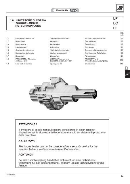
1.0 LIMITATORE DI COPPIA<br />
TORQUE LIMITER<br />
RUTSCHKUPPLUNG<br />
1.1 Caratteristiche tecniche Technical characteristics Technische Eigenschaften D2<br />
1.2 Descrizione Description Beschreibung D2<br />
1.3 Designazione Designation Bezeichnung D3<br />
1.4 Lubrificazione Lubrication Schmierung D5<br />
1.5 Caratteristiche tecniche Technical characteristics Technische Besonderheiten D6<br />
1.6 Disposizione delle molle Springs arrangement Anordnung der Tellerfedern D8<br />
1.7 Dimensioni Dimensions Abmessungen D9<br />
1.8 PROSSIMITI e Rivelatore<br />
di blocco RDB<br />
CT16IGBD2<br />
ATTENZIONE !<br />
Il limitatore di coppia non può essere considerato in alcun caso un<br />
dispositivo per la sicurezza dell’operatore ma solo un sistema di protezione<br />
della macchina.<br />
ATTENTION !<br />
The torque limiter can not be considered as a security device for the<br />
operator but as a protection system for the machine.<br />
ACHTUNG !<br />
PROXIMITY sensor and<br />
Locked Shaft detector RDB<br />
PROXIMITY und<br />
Wellenblockiererfassung RDB<br />
1.9 Lista parti di ricambio Spare parts list Ersatzteilliste D13<br />
Bei der Rutschkupplung handelt es sich nicht um eine Sicherheitsvorrichtung<br />
für das Bedienpersonal, sondern um ein Schutzsystem für die<br />
Anlage.<br />
<strong>LP</strong><br />
<strong>LC</strong><br />
<strong>LF</strong><br />
Pag.<br />
Page<br />
Seite<br />
D10<br />
D1<br />
D
1.1 Caratteristiche tecniche<br />
Il limitatore di coppia STM è utile in tutti i<br />
casi nei quali si voglia proteggere una trasmissione<br />
da sovraccarichi, urti e qualunque<br />
irregolarità della coppia assorbita dall’utilizzatore.<br />
Nei confronti delle frizioni tradizionali presenta<br />
numerosi vantaggi:<br />
D2<br />
è incorporato, senza variazioni dimensionali,<br />
nei riduttori a vite senza fine<br />
semplici RI/RMI, combinati CRI/CRMI e<br />
con precoppia CR/CB nella gamma<br />
delle grandezze 28,40,50,63,70,85,<br />
110,130,150.<br />
è protetto da qualunque contaminante<br />
(acqua, polvere, olio, grasso),ecc.<br />
è concepito per lavorare a bagno d’olio,<br />
cosa che lo rende affidabile nel tempo<br />
ed esente da usura.<br />
è facilmente regolabile dall’esterno tramite<br />
il serraggio di un dado esagonale.<br />
può slittare anche per diversi minuti<br />
senza danneggiarsi.<br />
Il limitatore di coppia è montato nel riduttore<br />
utilizzando cuscinetti radiali ed escludendo<br />
l’applicazione di cuscinetti conici<br />
in quanto i carichi assiali generati da questi<br />
ultimi provocherebbero alterazioni nella<br />
taratura del limitatore stesso.<br />
Nel par. 1.5 sono riportati i valori della<br />
coppia di slittamento del limitatore in<br />
funzione del numero di giri del dado di<br />
regolazione o della ghiera.<br />
Ricordiamo inoltre che su specifica richiesta,<br />
nei riduttori combinati, è possibile<br />
montare il limitatore di coppia sul primo<br />
riduttore (più piccolo) con la possibilità di<br />
mantenere l’irreversibilità del gruppo,<br />
qualora la scelta dei rapporti la preveda, e<br />
con un costo più contenuto del dispositivo.<br />
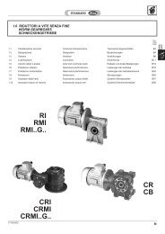
1.2 Descrizione<br />
Il limitatore di coppia STM è costruito nelle<br />
configurazioni:<br />
<strong>LP</strong> (albero sporgente),<br />
<strong>LC</strong> (albero cavo, non passante)<br />
<strong>LF</strong> (albero cavo passante).<br />
Facendo riferimento alle figure, la trasmissione<br />
del moto avviene per attrito fra le superfici<br />
dell’albero (6) della corona dentata<br />
(5) e della bussola (7) che vengono sottoposte<br />
ad una determinata compressione<br />
(regolabile) per mezzo dell’azione esercitata<br />
sulle molle a tazza (2) dal dado di regolazione<br />
o dalla ghiera (1).<br />
1.1 Technical characteristics 1.1 Technische Eigenschaften<br />
STM torque limiter is useful in all those<br />
cases where it is necessary to protect a<br />
transmission from overloads, shocks and<br />
any other torque irregularities.<br />
Several are the advantages that it offers<br />
when compared with traditional clutches:<br />
it is built-in in the wormgearboxes type<br />
RI-RMI, in the combined units type<br />
CRI/CRMI and with primary reduction<br />
type CR/CB in sizes 28,40,50,<br />
63,70,85,110,130,150 without any<br />
design modifications.<br />
it is protected from any possible polluting<br />
agents (water, dust, oil, grease) etc.<br />
it has been designed for oil-bath operation<br />
therefore reliable and wearfree.<br />
it is easily adjustable from outside by<br />
turning a standard hexagonal nut.<br />
it can slip for several minutes at a time<br />
without damage.<br />
The torque limiter is assembled on to the<br />
gearbox by means of radial bearings and<br />
not taper roller bearings since the axial<br />
loads created by them could alter the<br />
calibration of the torque limiter itself.<br />
On chapter 1.5 are listed the values of the<br />
slipping torque of the torque limiter in<br />
operation and of the nut’s number of turns.<br />
It is important to draw the attention on the<br />
fact that, upon request, it is possible to<br />
assemble the torque limiter on to the first<br />
gearbox (the smaller one) in the combined<br />
units and this will not affect the irreversibility<br />
of the unit depending on the ratios of the<br />
gearboxes. As a result the unit will certainly<br />
be less expensive.<br />
1.2 Description 1.2 Beschreibung<br />
STM torque limiter is manufactured in the<br />
following versions:<br />
<strong>LP</strong> ( extended shaft )<br />
<strong>LC</strong> ( hollow shaft )<br />
<strong>LF</strong> ( through hollow shaft )<br />
With reference to pictures shown below,<br />
transmission of movement takes place by<br />
means of friction between the shaft, the<br />
wormwheel and the bushing.<br />
They are infact subject of a determined<br />
compression ( which can be adjusted )<br />
created by the effect of the nut on the<br />
washers.<br />
Ist ein Schutz vor Überlastungen, stoßartigen<br />
Belastungen etc. erforderlich, so ist die<br />
integrierte Rutschkupplung von STM eine<br />
unentbehrliche Zusatzausstattung.<br />
Sie bietet immer dann Vorteile, wenn die<br />
normale Belastung eines Antriebes überschritten<br />
wird.<br />
Integriert in die Standardschneckengetriebe<br />
RI/RMI, Doppelschneckengetriebe<br />
CRI/CRMI und Stirnradschneckengetriebe<br />
CR/CB; alle Ausführungen in den<br />
Größen 28, 40, 50, 63, 70, 85, 110, 130<br />
und 150.<br />
durch die integrierte Bauweise geschützt<br />
gegen äußere Einflüsse wie Staub,<br />
Wasser, Öl, Fett, etc.<br />
im Ölbad laufend, dadurch zuverlässig<br />
und wartungsfrei.<br />
einfache Drehmomenteinstellung durch<br />
eine von außen zugängliche Einstellmutter.<br />
Schlupf über einen längeren Zeitraum<br />
hinweg fügt der Kupplung keinen Schaden<br />
zu, allerdings ist die erhöhte Erwärmung<br />
bei Dauerschlupf zu beachten.<br />
Schneckengetriebe mit Rutschkupplung<br />
können nur mit Radiallagern ausgestattet<br />
werden. Zur Einstellung des Schlupfmomentes<br />
ist eine Axialverschiebung des<br />
Druckringes erforderlich, was den Einsatz<br />
von Kegelrollenlagern verhindert.<br />
Das gewünschte Schlupfmoment kann mit<br />
Hilfe der Einstellmutter auf Basis der Werte<br />
kapitel 1.5 eingestellt werden.<br />
Bei Doppelschneckengetrieben ist es auf<br />
Wunsch möglich, die Rutschkupplung in die<br />
erste Stufe zu integrieren. Dadurch wird die<br />
mögliche Selbsthemmung des Getriebes<br />
erhalten und die Rutschkupplung kann<br />
kleiner dimensioniert werden.<br />
Dies ist jedoch nur bei geeigneten<br />
Untersetzungsverhältnissen möglich.<br />
Die STM Rutschkupplung wird mit unterschiedlichenAusgangswellenausführungen<br />
produziert:<br />
<strong>LP</strong> Vollwelle<br />
<strong>LC</strong> Hohlwelle einseitig<br />
<strong>LF</strong> Hohlwelle durchgehend<br />
Die Drehmomentübertragung findet durch<br />
Reibschluß zwischen dem Konus der<br />
Abtriebswelle und dem Schneckenrad statt.<br />
Die (einstellbare) Reibkraft wird durch die<br />
auf den Druckring wirkende Kraft der<br />
Tellerfedern erzeugt.<br />
CT16IGBD2
La scelta ottimale dei materiali della corona<br />
(bronzo GCuSn12 UNI 7013) e dell’albero e<br />
della bussola (acciaio temprato e rettificato)<br />
consente di garantire delle durate molto<br />
elevate anche in presenza di frequenti<br />
slittamenti.<br />
1.3 Designazione<br />
RI<br />
RMI<br />
CRI<br />
CRMI<br />
CR<br />
CB<br />
CT16IGBD2<br />
Riduttore<br />
Gearbox<br />
Getriebe<br />
B4<br />
<strong>LP</strong><br />
<strong>LC</strong><br />
<strong>LF</strong><br />
Versione<br />
Version<br />
Version<br />
<strong>LP</strong><br />
<strong>LC</strong><br />
<strong>LF</strong><br />
The perfect choice of the wormheel material<br />
( bronze GCuSn12 UNI 7013 ) together<br />
with the shaft and bushings which are made<br />
out of ground and hardened steel, enable<br />
the manufacturer to guarantee long life<br />
even with frequent slippings.<br />
Eine optimale Werkstoffkombination - beim<br />
Schneckenrad Bronze GCuSn 12 Uni 7013<br />
und bei der Welle gehärteter und geschliffener<br />
Stahl - garantieren auch bei häufigem<br />
Schlupf eine hohe Lebensdauer.<br />
1.3 Configuration 1.3 Beschreibung<br />
Lato uscita moto<br />
Motion output<br />
Abtriebsseite<br />
A<br />
B<br />
Taratura maggiorata<br />
Heavy calibration<br />
Erhöhtes<br />
Ansprechmoment<br />
TM<br />
Opzionale solo<br />
per RI, RMI<br />
Optional only<br />
for RI, RMI<br />
Als Option nur<br />
für RI, RMI<br />
Sensore<br />
Detector<br />
Geber<br />
Pro<br />
Esempio / Example / Beispiel<br />
RMI 40S 1:20 63 B5 <strong>LP</strong>A<br />
RMI40S1:20T56A463<strong>LC</strong>A (TM)<br />
RI 40S 1:20 <strong>LF</strong>A (TM)<br />
D3<br />
D
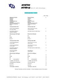
Alla designazione del riduttore, determinata<br />
reperendo i dati necessari nei rispettivi<br />
cataloghi, deve seguire la lettera L che<br />
contraddistingue il limitatore incorporato,<br />
unitamente alla versione desiderata:<br />
P albero sporgente<br />
C albero cavo non passante<br />
F albero cavo passante<br />
E’ molto importante precisare anche il lato<br />
dove si desidera l’uscita del moto A, B,<br />
avvalendosi degli schemi riportati nelle<br />
pagine seguenti, ricordando che, ovviamente,<br />
dalla parte opposta dell’uscita sarà<br />
possibile effettuare la taratura del limitatore<br />
agendo sull’apposito dado o ghiera.<br />
Per la determinazione della posizione dell’ albero<br />
di uscita nelle versioni a piedi o PP, è<br />
sufficiente osservare il riduttore dalla parte<br />
entrata-moto o ( per la versione di montaggio<br />
D) lato vite ; se l’albero è desiderato sul<br />
lato sinistro, la posizione di montaggio del<br />
limitatore sarà in esecuzione A, viceversa,<br />
se l’ albero è a destra si dovrà richiedere<br />
l’esecuzione B.<br />
Nelle versioni FL o P, l’esecuzione A è<br />
considerata quella che prevede l’uscitamoto<br />
dal lato del coperchio chiuso o<br />
coperchio FO (lato opposto alla flangia);<br />
l'esecuzione B è invece quella in cui<br />
l'uscita-moto è dalla stessa parte della<br />
flangia FL o P.<br />
A tale proposito si desidera evidenziare che<br />
nelle versioni FL non è stata riportata<br />
l’uscita A (anche se tecnicamente fattibile)<br />
in quanto la ghiera o il dado si troverebbero<br />
all’interno della flangia stessa, pertanto<br />
difficilmente accessibili.<br />
Fig. 3.1<br />
Lato uscita moto<br />
Motion output<br />
Abtriebsseite<br />
D4<br />
Once the right designation of the gearbox<br />
has been selected following the indications<br />
reported in the respective catalogues, letter<br />
L must be added to indicate the built-in<br />
limiter together with the required version:<br />
P double extended shaft<br />
C hollow shaft<br />
F through hollow shaft<br />
It is also essential to specify where the<br />
output of motion A and B is required<br />
according to the diagram shown in the<br />
following page reminding that on the<br />
opposite side of the output it is possible to<br />
carry out the limiter calibration by acting on<br />
to the appropriate nut or ring nut.<br />
In order to determine the position of the<br />
output shaft in foot or PP version, it is<br />
enough to look at the gearbox from the<br />
input side or wormshaft side (mounting<br />
position D), if shaft is required on to the left<br />
hand side, mounting position of limiter will<br />
be A, on the contrary, if shaft is required on<br />
to the right hand side, version B should be<br />
required.<br />
In the FL or P versions, execution A is the<br />
one that provides the output of motion from<br />
the closed cover or FO cover (on the<br />
opposite side of the flange); execution B,<br />
instead, is the one that provides the output<br />
of motion from FL or P side.<br />
On this purpose, it is important to draw<br />
user’s attention on the fact that in these<br />
versions output A has not been highlighted<br />
although available as the nut or ring nut<br />
would be located inside the same flange<br />
and therefore hardly accessible.<br />
Nach der Wahl des Getriebetyps (basierend<br />
auf den im jeweiligen Katalogabschnitt<br />
zu findenden Angaben) wird der<br />
Getriebespezifikation bei Bedarf einer Rutschkupplung<br />
der Buchstabe L hinzugefügt.<br />
Der Typ der Rutschkupplung muß folgendermaßen<br />
gekennzeichnet werden:<br />
P Vollwelle<br />
C einseitig Hohlwelle<br />
F durchgehend Hohlwelle<br />
Außerdem muß die Abtriebsseite A, B mit<br />
Hilfe der anschließend aufgeführten<br />
Skizzen angegeben werden - unter<br />
Berücksichtigung, daß die Einstellmutter<br />
sich auf der dem Abtrieb gegenüberliegenden<br />
Seite befindet .<br />
Zur Bestimmung der Lage der Abtriebswelle<br />
wird ein Getriebe in Fußversion oder<br />
Version PP von der Eingangsseite oder (bei<br />
der Montageversion D) von der<br />
Schraubenseite betrachtet: befindet sich die<br />
Welle auf der linken Seite, ist die Montagestellung<br />
des Drehmomentbegrenzers Ausführung<br />
A, andernfalls - wenn die Welle sich<br />
auf der rechten Seite befindet-handelt es<br />
sich um Ausführung B.<br />
Bei den Versionen in einfacher P- oder<br />
Flanschausfuhrung ist zu beachten, daß<br />
bei der Ausführung A der Abtrieb auf der<br />
Seite des geschlossenen oder FO-Deckels<br />
(gegen- über dem Flansch), liegt folglich<br />
befindet sich die Einstellmutter dann im<br />
Flansch. Da die Einstellmutter in diesem<br />
Fall nur sehr schwer zugänglich ist, wurde<br />
diese Ausführung hier nicht aufgelistet, ist<br />
jedoch technisch realisierbar und auf<br />
Wunsch auch erhältlich.<br />
Lato uscita moto<br />
Motion output<br />
Abtriebsseite<br />
CT16IGBD2
N.B. La scelta della posiz. A e B dell’ albero<br />
uscita è indipendente dalla versione di<br />
montaggio del riduttore.<br />
CT16IGBD2<br />
RI<br />
RMI<br />
CRI<br />
CRMI<br />
CR<br />
CB<br />
Per i riduttori 40, 50, 63, 70 previsti con<br />
doppia flangia pendolare fare riferimento alla<br />
versione P standard.<br />
1.4 Lubrificazione<br />
Tutti i riduttori con limitatore di coppia<br />
devono essere lubrificati ad olio.<br />
La lubrificazione a grasso non è possibile.<br />
E’ possibile utilizzare i lubrificanti indicati<br />
nella tab. 1.8 par. 1.6-A attenendosi<br />
comun- que alle indicazioni generali di<br />
manutenzione.<br />
NOTE. Choice of shaft positions A and B<br />
are not related to mounting position of<br />
gearbox.<br />
For gearboxes 40, 50, 63, 70 with double<br />
shaft-mounted flange, refer to the standard P<br />
version.<br />
1.4 Lubrication 1.4 Schmierung<br />
All gearboxes equipped with a torque limiter<br />
must be oil lubricated.<br />
Grease lubrication is not possible.<br />
The lubricants listed in the tab. 1.8 on the<br />
chapter 1.6-A can be used but it is always<br />
advisable to follow the general indications<br />
of maintenance.<br />
HINWEIS. Die Wahl der Abtriebsposition A<br />
oder B ist unabhängig von der<br />
Montageposition des Getriebes.<br />
Für Getriebe 40, 50, 63, 70 PP wird auf die<br />
Standardausführung P verwiesen.<br />
Alle mit Rutschkupplungen ausgestatteten<br />
Schneckengetriebe müssen ölgeschmiert<br />
sein.<br />
Eine Fettschmierung ist nicht möglich.<br />
Unter Berücksichtigung der allgemeinen<br />
Instandhaltungsanweisungen können die in<br />
Tabelle 1.8 kapitel 1.6-A aufgelisteten<br />
Schmiermittel verwendet werden.<br />
D5<br />
D
1.5 Caratteristiche tecniche<br />
Nelle tabelle seguenti sono riportate le<br />
coppie di slittamento M2S in funzione del<br />
numero dei giri del dado, o della ghiera di<br />
regolazione ottenibili con la disposizione<br />
standard delle molle (par. 1.6 ).<br />
Tali valori prescindono dalle prestazioni<br />
delle dentature.<br />
Valori più elevati di M2S si possono ottenere,<br />
a richiesta, con una diversa disposizione<br />
delle molle.<br />
I valori di taratura si riferiscono ad una<br />
condizione statica(durante lo slittamento la<br />
coppia trasmessa decade considerevolmente)<br />
ed hanno un significato indicativo in<br />
quanto ottenuti per via teorica.<br />
E’ opportuno verificare periodicamente la<br />
coppia di taratura soprattutto durante la<br />
prima fase di funzionamento.<br />
D6<br />
<strong>LP</strong><br />
<strong>LC</strong><br />
1.5 Technical characteristics 1.5 Technische Besonderheiten<br />
In the following tables the slipping torques<br />
M2S are listed according to number of turns<br />
of nut or ring nut obtainable with a standard<br />
arrangement of the springs (chapter 1.6).<br />
Such data prescind from tothing performances.<br />
M2S higher values can eventually be<br />
obtained with a different arrangement of<br />
the springs.<br />
Calibration values refer to a static condition<br />
(during slippage torque reports a considerable<br />
decrease) and are approximate<br />
being calculated on a theoric basis. It is<br />
important therefore to check the calibration<br />
torque periodically especially during first<br />
phase of running.<br />
In der folgenden Tabelle sind die Rutschmomente<br />
M2S dargestellt, wie sie je nach<br />
Stellung der Sechskant- oder Nutmutter mit<br />
der Standardanordnung der Tellerfedern<br />
erreicht werden (siehe kapitel 1.6).<br />
Diese Werte lassen die maximal übertragbare<br />
Leistung der Getriebe in Abhängigkeit<br />
von der Untersetzung jedoch außer acht.<br />
Mit einer anderen Anordnung der Tellerfedern<br />
können auch größere Rutschmomente<br />
M2S erreicht werden.<br />
Die angegebenen Werte sind statische<br />
Momente (das Rutschmoment nimmt während<br />
des Schlupfvorganges ab) und sind<br />
nur als Näherungswerte zu betrachten.<br />
Das eingestellte Rutschmoment sollte in<br />
der Einlaufphase in periodischen<br />
Abständen überprüft und gegebenenfalls<br />
korrigiert werden.<br />
ir<br />
M2S (Nm)<br />
N. GIRI DEL DADO DI REGOLAZIONE<br />
NUMBER OF TURNS OF ADJUSTEMENT RING NUT<br />
DREHUNGEN DER EINSTELLMUTTER<br />
1/2 2/3 1 1 1/3 1 2/3 2 2 1/3 2 2/3 3 3 1/3 3 2/3<br />
28<br />
4 5.5 7.5 10 13<br />
40 tutti i rapporti 12 16 24 31 38 46<br />
50<br />
63<br />
all ratios<br />
alle<br />
Untersetzungen<br />
16<br />
21<br />
20<br />
27<br />
29<br />
41<br />
39<br />
55<br />
47<br />
65<br />
55<br />
79<br />
63<br />
89 101 112 124<br />
70 21 27 41 55 65 79 89 101 112 124<br />
RI<br />
RMI<br />
85<br />
7-10-15-28 60 79 113.5 148 175 210 236 265 298 323 345<br />
20-40-49 66 87 125 163 192.5 231 260 292 328 356 380<br />
56 - 100 72 95 136 178 210 253 284 319 358 388 415<br />
7-10-15-28 106 141 207 271 334 392 454 516 572 630<br />
110 20-40-49 114 152 224 293 361 423 490 557 618 680<br />
56 - 100 131 174 257 336 414 486 640 709 781<br />
130 tutti / all / alle 240 310 450 590 720 850 950<br />
150 tutti / all / alle 550 730 1070 1390 1700 1990 2200<br />
RI<br />
RMI<br />
CRI<br />
CRMI<br />
ir<br />
M2S (Nm)<br />
N. GIRI DEL DADO DI REGOLAZIONE<br />
NUMBER OF TURNS OF ADJUSTEMENT RING NUT<br />
DREHUNGEN DER EINSTELLMUTTER<br />
Taratura maggiorata<br />
Heavy calibration<br />
Erhoete eichung 1/2 2/3 1 1 1/3 1 2/3 2 2 1/3<br />
28 28<br />
12.5 17 24<br />
40<br />
50<br />
63<br />
40<br />
50<br />
63<br />
tutti i rapporti<br />
all ratios<br />
alle<br />
Untersetzungen<br />
40<br />
50<br />
96<br />
53<br />
65<br />
125<br />
77<br />
93<br />
178<br />
91<br />
128<br />
231 288<br />
tutti/all/alle 40<br />
50<br />
70 70 96 125 178 231 288 tutti/all/alle 70<br />
85 85<br />
7-10-15-28 146 185 263 350 414 471 542 43.0 - 128.8 85<br />
20-40-49 161 204 289 385 456 518 596 167.6 - 225.4<br />
56 - 100 176 223 316 420 497 566 651 286.4 - 460.0<br />
7-10-15-28 261 342 501 653 805 945 43.0 - 128.8 110<br />
110 110 20-40-49 282 369 541 705 869 1021 167.6 - 225.4<br />
56 - 100 323 424 621 810 998 1172 286.4 - 460.0<br />
130 130 tutti / all / alle 470 620 910 1180 1450 1700 1900<br />
150 150 tutti / all / alle 830 110 1600 2050 2500 3000 3350<br />
ir<br />
CR<br />
CB<br />
CT16IGBD2
1.5 Caratteristiche tecniche<br />
ATTENZIONE!<br />
Quando è richiesto il minimo errore di<br />
taratura è opportuno verificare in pratica,<br />
staticamente, che la frizione slitti effettivamente<br />
al valore desiderato è comunque<br />
consigliabile testare la coppia trasmissibile<br />
direttamente sulla macchina utilizzatrice.<br />
<strong>LF</strong><br />
CT16IGBD2<br />
RI<br />
RMI<br />
ir<br />
1.5 Technical characteristics 1.5 Technische Besonderheiten<br />
ATTENTION!<br />
When minimum calibration error is required<br />
it is always advisable to actually verify,<br />
statically, that clutch slips at the required<br />
value. We suggest, however, to test the<br />
torque directly on to the machine.<br />
M2S (Nm)<br />
ACHTUNG!<br />
Um Abweichungen zu vermeiden, müssen<br />
die eingestellten Momente im eingebauten<br />
Zustand kontrolliert und eventuell korrigiert<br />
werden.<br />
N. GIRI DELLA GHIERA DI REGOLAZIONE<br />
N. OF TURNS OF ADJUSTEMENT RING NUT<br />
DREHUNGEN DER EINSTELLMUTTER<br />
1/4 1/2 2/3 1 1 1/3 1 2/3 2 2 1/3 2 2/3 3 3 1/3 3 2/3 4<br />
15 28 36 51 64 75 86 97<br />
40<br />
50<br />
tutti i rapporti<br />
all ratios 21 40 52 74 93 110 126 141 154 167<br />
63<br />
alle<br />
Untersetzungen 27 51 66 93 120 140 160 175 195 210<br />
70 24 45 58 81 100 115 125 135 145 151 155 160<br />
85<br />
7-10-15-28 50 85 115 160 200 240 280 310 340 370 395 420<br />
20-40-49 60 95 120 170 220 265 300 340 370 400 430 460<br />
56-70-80-100 80 100 130 190 240 290 330 370 400 440 470 500<br />
7-10-15-28 140 260 340 490 630 750 860 960 1060 1150 1230 1310 1390<br />
110 20-40-49 150 285 370 530 670 800 930 1040 1140 1230 1330 1410 1500<br />
56-70-80-100 170 330 430 600 770 930 1060 1190 1300 1415 1520 1620 1720<br />
130 tutti / all / alle 244 476 625 910 1180 1438 1686 1920 2160 2390<br />
150 tutti / all / alle 550 860 1130 1660 2170 2660 3140 3600 4050 4500 4930 5370<br />
RI<br />
RMI<br />
CRI<br />
CRMI<br />
Taratura<br />
maggiorata<br />
Heavy calibration<br />
Erhoete eichung<br />
40 40<br />
ir<br />
1/4 1/2 2/3 1<br />
M2S (Nm)<br />
N. GIRI DELLA GHIERA DI REGOLAZIONE<br />
N. OF TURNS OF ADJUSTEMENT RING NUT<br />
DREHUNGEN DER EINSTELLMUTTER<br />
1<br />
1/3<br />
1<br />
2/3<br />
2<br />
2<br />
1/3<br />
2<br />
2/3<br />
3 3 1/3 3 2/3 4<br />
15 28 36 51 64 75 86 97 tutti /all /alle 40<br />
50 50<br />
tutti i rapporti<br />
all ratios 21 40 52 74 93 110 126 141 154 167 50<br />
63 63<br />
alle<br />
Untersetzungen 51 100 130 190 245 295 345 385 440 480<br />
70 70 38 74 96 135 175 210 240 270 300 320 350 tutti /all /alle 70<br />
85 85<br />
7-10-15-28 100 125 160 230 300 360 410 460 510 560 600 640 680 43.0 - 128.8 85<br />
20-40-49 110 135 180 255 330 390 450 510 560 610 650 700 750 167.6 - 225.4<br />
56-70-80-100 120 150 195 280 350 425 490 550 610 665 715 765 815 286.4 - 460.0<br />
7-10-15-28 190 380 500 740 930 1150 1350 1500 1700 1850 2020 2180 — 43.0 - 128.8 110<br />
110 110 20-40-49 200 400 540 780 1000 1230 1430 1620 1800 2000 2170 2360 — 167.6 - 225.4<br />
56-70-80-100 220 450 600 900 1150 1380 1620 1840 2070 2300 2500 2700 — 286.4 - 460.0<br />
130 130 tutti /all / alle 244 476 625 910 1180 1438 1686 1920 2160 2390<br />
150 150 tutti /all / alle 550 860 11301660 2170 2660 3140 3600 4050 4500 4930 5370<br />
ir<br />
CR<br />
CB<br />
D7<br />
D
1.6 Disposizione delle molle<br />
La disposizione standard delle molle garantisce<br />
una buona sensibilità di regolazione<br />
e consente di trasmettere la massima<br />
coppia nominale del riduttore.<br />
D8<br />
<strong>LP</strong><br />
<strong>LC</strong><br />
<strong>LF</strong><br />
28<br />
40<br />
50<br />
63<br />
70<br />
85<br />
110<br />
130<br />
150<br />
40<br />
50<br />
63<br />
70<br />
85<br />
110<br />
130<br />
150<br />
RI- RMI<br />
5 molle/springs<br />
20/10.2/1.1<br />
5 molle/springs<br />
23/12.2/1.5<br />
5 molle/springs<br />
31.5/16.3/1.75<br />
7 molle/springs<br />
31.5/16.3/2<br />
7 molle/springs<br />
34/16.3/2<br />
10 molle/springs<br />
40/18.3/2<br />
10 molle/springs<br />
45/22.4/2.5<br />
3 molle/springs<br />
60/30.5/3.5<br />
6 molle/springs<br />
60/30.5/3.5<br />
RI- RMI<br />
2 molle/springs<br />
80/41/3<br />
2 molle/springs<br />
90/46/2.5<br />
2 molle/springs<br />
100/51/3.5<br />
2 molle/springs<br />
125/61/5<br />
Per problemi specifici è opportuno consultarci,<br />
ma a livello indicativo si può affermare<br />
che accoppiando più molle con lo stesso<br />
verso (in parallelo) si incrementa la coppia<br />
massima di slittamento raggiungibile;<br />
viceversa alternandone il posizionamento<br />
in serie si aumenta la sensibilità di taratura.<br />
1.6 Springs arrangement 1.6 Anordnung der Tellerfedern<br />
Standard arrangement of springs guarantees<br />
an acceptable setting and enables the<br />
gearbox to transmit the maximum nominal<br />
torque<br />
RI - RMI<br />
Taratura maggiorata<br />
Heavy calibration<br />
Erhoete eichung<br />
RI - RMI<br />
Taratura maggiorata<br />
Heavy calibration<br />
Erhoete eichung<br />
CRI - CRMI CR - CB<br />
6 molle/springs<br />
20/10.2/1.1<br />
6 molle/springs<br />
23/12.2/1.5<br />
6 molle/springs<br />
31.5/16.3/1.75<br />
6 molle/springs<br />
31.5/16.3/2<br />
6 molle/springs<br />
34/16.3/2<br />
9 molle/springs<br />
40/18.3/2<br />
9 molle/springs<br />
45/22.4/2.5<br />
6 molle/springs<br />
60/30.5/3.5<br />
9 molle/springs<br />
60/30.5/3.5<br />
2 molle/springs<br />
63/31/2.5<br />
2 molle/springs<br />
80/41/3<br />
2 molle/springs<br />
125/75.5/6<br />
2 molle/springs<br />
150/81/8<br />
2 molle/springs<br />
80/41/4<br />
Should the user require any specific<br />
information, we suggest to contact our<br />
technical department. On a general basis,<br />
how- ever, if the springs are arranged in the<br />
same direction, a higher maximum torque<br />
of slippage can be reached; on the contrary<br />
by alternating their arrangement the<br />
calibration sensitivity is increased.<br />
—<br />
—<br />
—<br />
CRI - CRMI CR - CB<br />
2 molle/springs<br />
90/46/3.5<br />
2 molle/springs<br />
100/51/4<br />
2 molle/springs<br />
125/61/6<br />
—<br />
—<br />
—<br />
Die Standardanordnung der Tellerfedern<br />
erlaubt eine feinfühlige Einstellung des<br />
Rutschmomentes bis zum maximalen<br />
Nennmoment des Getriebes.<br />
2<br />
3<br />
5<br />
6<br />
7<br />
9<br />
10<br />
IN PARALLELO<br />
max. coppia<br />
min. sensibilita’<br />
PARALLEL<br />
max. torque<br />
min. sensitivity<br />
PARALLEL<br />
max. Moment<br />
min. Empfindlichkeit<br />
IN SERIE<br />
min. coppia<br />
max. sensibilita’<br />
SERIES<br />
min. torque<br />
max. sensitivity<br />
SERIE<br />
min. Moment<br />
max. Empfindlichkeit<br />
Das Rutschmoment ist umso größer, je<br />
mehr Tellerfedern parallel angeordnet sind<br />
(progressive Federkennlinie). Wird ein niedrigeres<br />
Moment oder eine erhöhte Justiergenauigkeit<br />
gewünscht, so können die<br />
Federn auch gegensinnig angeordnet werden<br />
(degressive Federkennlinie).<br />
Sollten spezifische Fragen bestehen, so<br />
empfehlen wir, unser technisches Büro zu<br />
Rate zu ziehen.<br />
CT16IGBD2
1.7 Dimensioni<br />
CT16IGBD2<br />
DownLoad<br />
2D/3D<br />
2D 3D<br />
1.7 Dimensions 1.7 Abmessungen<br />
H5<br />
<strong>LP</strong><br />
RI - RMI - CRI - CRMI<br />
28 40 50 63 70 85 110 130 150<br />
Ch 17 19 22 24 24 27 32 46 46<br />
b2 5 6 8 8 8 10 12 14 16<br />
d1 17 22 28 32 34 38 50 60 63<br />
d2 k6 14 19 24 25 28 32 42 48 55<br />
t2 16 21.5 27 28 31 35 45 51.5 59<br />
A2 29.5 40 45 60 60 71 100 110 110<br />
B2 31.5 51 59 65 70 71 87.5 110 125<br />
C2 41 49 60 70 66 75 94.5 119 112<br />
h2 5 7 7.5 8 10 10 10 10 10<br />
g2 20 25 30 40 40 50 80 90 90<br />
m2<br />
M6 M8 M8 M8 M8 M10 M10 M10 M12<br />
40 50 70 85 110<br />
CR -CB<br />
RI - RMI - CRI - CRMI<br />
28 40 50 63 70 85 110 130 150<br />
Ch 17 19 22 24 24 27 32 46 46<br />
b2 5 6 8 8 8 10 12 14 16<br />
DH7<br />
14 19 24 25 28 32 42 48 55<br />
<strong>LC</strong> t2 16.3 21.8 27.3 28.3 31.3 35.3 45.3 51.8 59.3<br />
C 30 41 49 60 60 61 77.5 90 105<br />
<strong>LF</strong><br />
C2 41 49 60 70 66 75 94.5 119 112<br />
I2 27 38 46 53 56 60 90 97 110<br />
g 4.5 5.5 7 7 9 9 11 11 11<br />
40 50 70<br />
CR-CB<br />
85 110<br />
RI - RMI - CRI - CRMI<br />
40 50 63 70 85 110 130 150<br />
DH7 19 24 25 28 32 42 48 55<br />
b2 6 8 8 8 10 12 14 16<br />
t2 21.8 27.3 28.3 31.3 35.3 45.3 51.8 59.3<br />
A1 25 31 32 36 40 51 59 66<br />
B1<br />
M30 M40 M40 M45 M50 M60 M75 M80<br />
C1 70 90 90 100 110 135 140 165<br />
C 41 49 60 60 61 77.5 90 105<br />
F2 60 74 85 85 84 110.5 130 155<br />
40 50 70<br />
CR-CB<br />
85 110<br />
<strong>LP</strong><br />
<strong>LC</strong><br />
<strong>LF</strong><br />
D9<br />
D
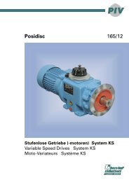
1.8 PROSSIMITI e Rivelatore<br />
di blocco RDB<br />
(Questo accessorio è disponibile per i<br />
riduttori RMI – CRMI - CB)<br />
Caratteristiche tecniche – sensore<br />
prossimiti<br />
D10<br />
1.8 PROXIMITY sensor and<br />
Locked Shaft detector RDB<br />
(This accessory is available for<br />
gearboxes RMI – CRMI - CB)<br />
Specifications – Proximity sensor<br />
PNP<br />
Marrone/Brown/Braun<br />
Nero/Black/Schwarz<br />
Blue/Blue/Blau<br />
Non schermato-Unshielded-Nicht geschirmt �<br />
Tensione di alimentazione - Supplyvoltage-Betriebsspannung 10..30Vdc<br />
Ondulazioneresidua-Ripple-Restwelligkeit < 10%<br />
Correntemassima di carico-Maximumloadcurrent-Maximaler Ladestrom 200mA<br />
Cadutaditensione-Voltagedrop-Spannungsabfall < 3V@200mA<br />
Assorbimento-Powerconsumption-Verbrauch < 10mA<br />
Ripetibilità-Repeatability-Wiederholbarkeit<br />
1.8 PROSSIMITI e Rivelatore<br />
di blocco RDB<br />
Fig.3.3 Contenitore / Casing / Gehäuse DIN H60 90x71x60<br />
Il sensore genera un segnale elettrico<br />
digitale discontinuo con una frequenza<br />
proporzionale alla velocità di rotazione<br />
dell’albero d’uscita del riduttore; la mancanza<br />
di segnale è interpretata dall’unità<br />
elettronica come condizione di blocco,<br />
evidenziata con l’accensione di una spia<br />
luminosa rossa (f) e l’attivazione di un relè<br />
di uscita i cui contatti possono essere utilizzati<br />
per un segnale d’allarme, per avviare<br />
una procedura automatica di blocco del<br />
ciclo produttivo o per interrompere l’alimentazione<br />
al motore che aziona il riduttore<br />
entrato in blocco.<br />
Come già accennato, il sensore genera un<br />
segnale ripetitivo di natura discontinua; ciò<br />
è da tenere in particolare considerazione in<br />
tutte le applicazioni caratterizzate da basse<br />
velocità in uscita dal riduttore in quanto<br />
l’intervallo di tempo che separa gli impulsi<br />
prodotti, può innescare il processo di<br />
riconoscimento del blocco.<br />
Questa eventualità può essere evitata<br />
imponendo al circuito un ritardo in base alle<br />
caratteristiche della motorizzazione, al fine<br />
di coprire con un certo margine gli intervalli<br />
di ripetizione del segnale compatibilmente<br />
con la sicurezza di funzionamento dell’<br />
apparecchiatura.<br />
La regolazione del tempo di intervento<br />
consentita dall’unità elettronica, può anche<br />
essere effettuata per imporre un ritardo alla<br />
segnalazione di blocco in casi dove<br />
brusche variazioni di velocità, di inerzia, o<br />
momentanee punte di carico determinano<br />
l’intervento del limitatore di coppia con<br />
conseguente arresto temporaneo<br />
dell’albero comandato.<br />
Ovviamente il ritardo dovrà essere sufficiente<br />
a consentire il ripristino delle normali<br />
condizioni di funzionamento, considerando<br />
che il protrarsi della condizione di<br />
blocco oltre il tempo impostato viene rilevato<br />
e segnalato dall’unità, la quale mantiene<br />
in memoria questo evento (anche se<br />
la rotazione dell’albero riprende) evidenziandolo<br />
visivamente con la spia rossa fino<br />
allo spegnimento dell' apparecchiatura<br />
dell'apparecchiatura o fino a che non si<br />
cancelli l’allarme premendo il pulsante di<br />
reset (g).<br />
CT16IGBD2<br />
1.8 PROXIMITY sensor and<br />
Locked Shaft detector RDB<br />
71<br />
45<br />
20<br />
42 11<br />
60<br />
62<br />
The sensor generates a digital discontinuous<br />
electronic signal at a frequency<br />
which is proportional to the rotational speed<br />
of the output shaft of the gearbox; every<br />
time the signal is not generated, the<br />
electronic unit activates an output relay,<br />
highlighted by means of a red led, that<br />
warns off the condition of locked shaft.<br />
The contact of the above relay may be<br />
used to activate an alarm that starts an<br />
automatic shutdown procedure or simply<br />
cuts off power to the motor which drives the<br />
locked gearbox.<br />
As mentioned above, the sensor generates<br />
a discontinuous repetitive signal.<br />
This is particularly important in all those<br />
applications characterized by low output<br />
speed since the time interval between the<br />
impulses generated by the detector could<br />
trigger detection of a locked shaft condition<br />
which does not actually exist.<br />
In order to prevent this possibility , the<br />
circuit can be programmed with a slight<br />
delay, according to motorization characteristics,<br />
to cover the signal repetition<br />
intervals without compromising the<br />
operating safety of the equipment.<br />
Regulation of interval time provided by the<br />
electronic unit can also be effected in order<br />
to impose a delay to the signalling of an<br />
actual locked shaft condition in all those<br />
cases where , during normal operation,<br />
sudden changes of speed or inertia or<br />
when there are temporary excesses in the<br />
load’s resisting moment, could determine<br />
the intervention of the torque limiter with<br />
subsequent temporary sotp of the shaft.<br />
Such delay should obviuosly be adequately<br />
long to reset the normal operating<br />
conditions. Infact, if the shaft reamins<br />
locked for longer than the set time, the<br />
condition is deteced and signalled to the<br />
equipment .<br />
The limiter has actually a memory function<br />
which is used to prevent the locked shaft<br />
condition from being cancelled even if the<br />
gearbox resumes rotation and it is<br />
highlighted by means of a red led, which<br />
remains on until the equipment is powered<br />
off or the alarm reset button (g) is<br />
depressed.<br />
1.8 PROXIMITY und<br />
Wellenblockiererfassung RDB<br />
90<br />
Der Sensor erzeugt ein Rechtecksignal, das<br />
in seiner Frequenz proportional zur<br />
Abtriebsdrehzahl des Getriebes ist.<br />
Bleibt dieses Signal aus oder sind die Signalpausen<br />
zu lang, so aktiviert die Auswertungseinheit<br />
neben einer roten LED (als<br />
optischen Hinweis) einen Relaiskontakt.<br />
Dieser kann eine übergeordnete Steuerungseinheit<br />
aktivieren oder die Stromversorgung<br />
des Motors unterbrechen.<br />
Wie bereits erwähnt, erzeugt der Sensor ein<br />
periodisches Rechtecksignal.<br />
Dies ist besonders bei solchen Einsatzarten<br />
wichtig, die durch langsame Ausgangsdrehzahlen<br />
gekennzeichnet sind.<br />
Wenn nämlich die Zeit zwischen zwei vom<br />
Sensor erzeugten Impulsen zu lange<br />
wäre, würde die Auswertungseinheit<br />
fälschlicherweise eine blockierte Welle<br />
melden. Um dem vorzubeugen, kann die<br />
Elektronik so programmiert werden, daß<br />
sie erst nach einer kurzen Verzögerung<br />
anspricht, aber dennoch schnell genug<br />
reagiert, um den Antrieb nicht zu<br />
gefährden.<br />
Die Einstellung der Rechtecksignaldauer<br />
dient auch zur Anlaufüberbrückung, um<br />
ein Ansprechen der Blockiererfassung<br />
während des Anlaufvorganges bzw. bei<br />
plötzlichen Drehzahländerungen zu<br />
verhindern.<br />
Die Ansprechverzögerung muß so justiert<br />
werden, daß sie erst nach einer gewissen<br />
Stillstandszeit der Welle, wie sie unter<br />
normalen Betriebsbedingungen auftreten<br />
kann, anspricht und diesen Zustand<br />
meldet. Dieses Ansprechen wird dann<br />
gespeichert, wodurch die Information auch<br />
nach dem Wiederanfahren der Einheit<br />
noch zur Verfügung steht.<br />
Optisch signalisiert wird dies durch das<br />
Aufleuchten der roten LED.<br />
Optisch signalisiert wird dies durch das<br />
Aufleuchten der roten LED bis zum<br />
Abschalten des Geräts oder bis der Alarm<br />
durch Drücken der Reset-Taste (g)<br />
gelöscht wird.<br />
D11<br />
D
1.8 PROSSIMITI e Rivelatore<br />
di blocco RDB<br />
Condizioni di funzionamento:<br />
Grado di protezione:<br />
IP00<br />
Temperatura di funzionamento<br />
della unità:<br />
0° � +50°C<br />
Temperatura di stoccaggio:<br />
-20° � +70°C<br />
Tensione di alimentazione:<br />
230 V(±10%)<br />
Frequenza di funzionamento:<br />
50-60 Hz<br />
Corrente assorbita:<br />
200mA<br />
(oltre i 250 l’apparecchio è protetto da<br />
fusibile autoripristinabile)<br />
Tempo di intervento:<br />
impostabile da 0.2 sec. a 8 sec.<br />
Morsettiera tipo:<br />
Phoenix contact MKDS 1,5/X<br />
(X sta per N° di poli)<br />
Massimo diametro filo serrabile:<br />
Rigido 2,5 mm 2<br />
Flessibile 1,5 mm 2<br />
Minimo diametro filo serrabile:<br />
0,14 mm 2<br />
Caratteristiche contatti Relè:<br />
Tensione applicabile 250 V<br />
Corrente massima 5 A<br />
Relativamente al tempo di intervento, è<br />
opportuno considerare che il minimo<br />
slittamento rilevabile con i sensori standard<br />
è di 25° quando la velocità di rotazione è<br />
tale da far rientrare il tempo impiegato per<br />
questo slittamento tra quelli possibili.<br />
N° di giri minimo rilevabili sull’ordine di 0.2<br />
min -1 dato che dipende dal modello del<br />
riduttore.<br />
Il sensore è fornito, senza specifica<br />
richiesta, con cavo non schermato: è<br />
consigliabile quindi sostituirlo con uno<br />
schermato.<br />
Per quanto riguarda le indicazioni<br />
sull'utilizzo del rivelatore di blocco si<br />
rimanda alle istruzioni allegate allo<br />
strumento stesso.<br />
D12<br />
1.8 PROXIMITY sensor and<br />
Locked Shaft detector RDB<br />
Operating conditions:<br />
Degree of protection:<br />
IP00<br />
Unit operating temperature:<br />
0° � +50°C<br />
Storage temperature:<br />
-20° � +70°C<br />
Voltage supply:<br />
230V (±10%)<br />
Operating frequency:<br />
50-60 Hz<br />
Current draw:<br />
200mA<br />
(above 250 mA, protection is ensured by a<br />
self-resetting fuse)<br />
Response time:<br />
0.2 sec. to 8 sec. setting range<br />
Terminal board type:<br />
Phoenix contact MKDS 1.5/X<br />
(X stands for no. of poles)<br />
Max wire diameter accepted:<br />
Stiff 2.5 sq mm<br />
Flexible 1.5 sq mm<br />
Min wire diameter accepted:<br />
0.14 sq mm<br />
Relay contact specifications:<br />
Input voltage 250 V<br />
Maximum current 5 A<br />
As regards response time, it should be<br />
noted that the minimum slip detected with<br />
standard sensors is 25° when rotational<br />
speed is such that slip time falls within<br />
allowed slip time range.<br />
Rpm resolution from 0.2 rpm (depends on<br />
gearbox model).<br />
Unless specified on order, sensor comes<br />
with unshielded cable; if so, replacement<br />
with a shielded cable is recommended.<br />
For information on locked shaft detector<br />
operation, please read the instructions<br />
supplied with the detector.<br />
1.8 PROXIMITY und<br />
Wellenblockiererfassung RDB<br />
Betriebsbedingungen:<br />
Schutzart:<br />
IP00<br />
Betriebstemperatur des Getriebes:<br />
0° � +50°C<br />
Lagertemperatur:<br />
-20° � +70°C<br />
Betriebsspannung:<br />
230V (±10%)<br />
Betriebsfrequenz:<br />
50-60 Hz<br />
Stromaufnahme:<br />
200mA<br />
(über 250 wird das Gerät von einer<br />
selbstrücksetzenden Sicherung geschützt)<br />
Auslösezeit:<br />
zwischen 0,2 Sek. bis 8 Sek. einstellbar<br />
Klemmenleiste - Typ:<br />
Phoenix contact MKDS 1,5/X<br />
(X steht für die Anzahl der Pole)<br />
Max. Durchmesser klemmbarer Draht:<br />
Steif 2,5 mm 2<br />
Flexibel 1,5 mm 2<br />
Min. Durchmesser klemmbarer Draht:<br />
0,14 mm 2<br />
Eigenschaften Relaiskontakte:<br />
Applizierbare Spannung 250 V<br />
Max. Strom 5 A<br />
Bezüglich der Auslösezeit sollte berücksichtigt<br />
werden, dass mit Standardsensoren<br />
der erfassbare min. Schlupf 25° beträgt,<br />
wenn die Drehgeschwindigkeit so ausfällt,<br />
dass die für diesen Schlupf aufgewendete<br />
Zeit wieder unter die möglichen Zeiten fällt.<br />
Erfassbare min. Drehzahl im Verhältnis 0,2<br />
min -1 , da sie vom Getriebemodell abhängt.<br />
Der Sensor wird, falls keine spezifische<br />
Anfrage erfolgt, mit ungeschirmtem Kabel<br />
geliefert: Es sollte daher durch ein geschirmtes<br />
Kabel ersetzt werden.<br />
Was die Betriebsanleitung des Blockiererfassunggeräts<br />
anbelangt, verweisen wir auf<br />
die dem Gerät beigelebten Anleitungen.<br />
CT16IGBD2
1.9 Lista parti di ricambio<br />
CT16IGBD2<br />
28-85<br />
1.9 Spare parts list 1.9 Liste der Ersatzteile<br />
<strong>LP</strong> 110 - 150<br />
28-85 <strong>LC</strong><br />
110 - 150<br />
1 Dado di regolazione Adjustment nut Einstelmutter<br />
2 Molle a tazza Washers Tellerfedern<br />
3 Guarnizione Gasket Öldichtung<br />
4 Linguetta Key Paßfeder<br />
5 Corona dentata Wheel Schneckenrad<br />
6A Albero uscita pieno Output shaft Ausgangsvollwelle<br />
6B Albero uscita cavo non passante Hollow shaft Ausgangshohlwelle<br />
7 Bussola Bushing Büchse<br />
8 Cono frizione Clutch cone Reibkonus<br />
Part. N° 28 40 50 63 70 85 110 130 150<br />
3 11.91 x 2.62 13.95 x 2.62 15.08 x 2.62 15.08 x 2.62 17.86 x 2.62 20.24 x 2.62 28.17 x 3.53 34.60 x 2.62 39.69 x 3.53<br />
Per i cuscinetti e anelli di tenuta fare riferimento<br />
al catalogo riduttori a vite senza fine.<br />
For the bearings and the oilseals please<br />
refer to our worm gearboxes catalogue.<br />
Für die Lager und Öldichtungen siehe<br />
unseren Schneckengetriebe - Katalog.<br />
D13<br />
D
1.9 Lista parti di ricambio<br />
D14<br />
40-63 <strong>LF</strong><br />
70 - 150<br />
1 Ghiera di regolazione Ring nut Sechakant oder nut<br />
2 Molle a tazza Washers springs Tellerfedern<br />
3 Distanziale Spacer Abstandscheibe<br />
4 Linguetta Key Paßfeder<br />
5 Corona dentata Wheel Schneckenrad<br />
6 Albero cavo passante Through hollow shaft Durchgehende Hohlwelle<br />
7 Bussola Bushing Büchse<br />
8 Cono frizione Clutch cone Reibkonus<br />
9 Guarnizione Gasket Öldichtung<br />
10 Cuscinetto Bearing Kügellager<br />
11 Anello di tenuta Oilseal Öldichtung<br />
12 Anello di tenuta Oilseal Öldichtung<br />
Part. N° 40 50 63 70 85 110 130 150<br />
9 26.70 x 1.78 37.82 x 1.78 37.82 x 1.78 41 x 1.78 47.35 x 1.78 56.87 x 1.78 71.12 x 2.62 72.62 x 3.53<br />
10<br />
6006<br />
30/55/13<br />
6008<br />
40/68/15<br />
1.9 Spare parts list 1.9 Liste der Ersatzteile<br />
6008<br />
40/68/15<br />
6009<br />
45/75/16<br />
6010<br />
50/80/16<br />
6012<br />
60/95/18<br />
6015<br />
75/115/20<br />
6216<br />
80/140/26<br />
11 30/47/7 40/56/8 40/56/8 45/60/7 50/65/8 60/75/8 75/95/10 80/100/10<br />
12 35/47/7 45/60/7 45/60/7 50/65/8 60/75/8 70/85/8 85/105/13 100/120/12<br />
CT16IGBD2