FIAT SCUDO VAN 10
FIAT SCUDO VAN 10
FIAT SCUDO VAN 10

You also want an ePaper? Increase the reach of your titles
YUMPU automatically turns print PDFs into web optimized ePapers that Google loves.
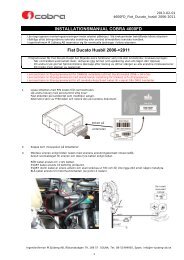
<strong>FIAT</strong><br />
MOD.<br />
<strong>SCUDO</strong><br />
<strong>VAN</strong><br />
VERS.<br />
SCHEDA TECNICA DI INSTALLAZIONE PER SITEMI DI ALLARME CAN<br />
CAN ALARM SYSTEM FITTING INSTRUCTIONS REV. 00<br />
www.cobra-at.com Morpheus 02.07.51<br />
Funzione<br />
Function<br />
CAN High<br />
CAN Low<br />
LOGIC BLINKER OUTPUT<br />
HAZARD<br />
Serie 44xx<br />
44xx series<br />
Rosso<br />
Red<br />
Nero<br />
Black<br />
Arancione<br />
Orange<br />
Viola<br />
Violet<br />
Giallo-Bianco<br />
Yellow-White<br />
Giallo-Verde<br />
Yellow-Green<br />
Auto<br />
Vehicle<br />
Azzurro<br />
Light blue<br />
Bianco<br />
White<br />
Azzurro<br />
Light blue<br />
Bianco<br />
White<br />
Bianco<br />
White<br />
Posizione<br />
Location<br />
Vedi foto 1.<br />
See photo 1.<br />
Vedi foto 2.<br />
See photo 2.<br />
1<br />
N.B. I dati forniti in questa scheda non sono impegnativi, pertanto devono essere ritenuti solo indicativi ai fini dell’installazione che dovrà essere<br />
eseguita in conformità a quanto riportato nel manuale di installazione del prodotto. Note: This information is not binding, therefore it must be<br />
considered only an example for installation purposes that must be executed as per the instructions given on the product installation manual.<br />
<strong>10</strong><br />
Filo da 4 mm² nel connettore grigio-giallo a 2 vie siglato AP.<br />
(Vedi foto 6 riferimento A)<br />
4 mm² wire of the grey-yellow 2-way connector<br />
(See photo 6 reference A)<br />
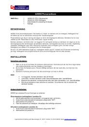
Collegare il filo alla derivazione di massa originale dietro al<br />
cassetto portaoggetti lato passeggero. (Vedi foto 3)<br />
Connect to the original ground terminal behind the<br />
glove compartment, passenger’s side. (See photo 3)<br />
Pos. n. 8 del connettore nero a <strong>10</strong> vie siglato PB<br />
(Vedi foto 6 riferimento B)<br />
Pos. n. 8 black <strong>10</strong>-way connector marked PB<br />
(See photo 6 reference B)<br />
Pos. n. <strong>10</strong> del connettore nero a <strong>10</strong> vie siglato PB<br />
(Vedi foto 6 riferimento B)<br />
Pos. n. <strong>10</strong> black <strong>10</strong>-way connector marked PB<br />
(See photo 6 reference B)<br />
Pos. n. 2 del connettore nero a <strong>10</strong> vie siglato PB.<br />
(Vedi foto 6 riferimento B)<br />
Pos. n. 2 black <strong>10</strong>-way connector marked PB.<br />
(See photo 6 reference B)<br />
Pos. n. 13 del connettore nero a 16 vie siglato PH1.<br />
(Vedi foto 6 riferimento C)<br />
Pos. n. 13 black 16-way connector marked PH1.<br />
(See photo 6 reference C)<br />
fiscv<strong>10</strong>c
Funzione<br />
Function<br />
+50<br />
Serie 44xx<br />
44xx series<br />
Verde<br />
Verde<br />
Green<br />
Green<br />
Auto<br />
Vehicle<br />
Bianco<br />
White<br />
Posizione<br />
Location<br />
(Vedi foto 4)<br />
(See photo 4)<br />
(Vedi foto 5)<br />
(See photo 5)<br />
Interrompere il filo da 0,50 mm² in pos. n. 6 del<br />
connettore bianco a <strong>10</strong> vie, siglato PB1.<br />
(Vedi foto 6 riferimento F)<br />
Interrupt the 0,50 mm² wire in pos. n. 6 of the<br />
<strong>10</strong>-way white connector, marked PB1.<br />
(See photo 6 reference F)<br />
N.B. In fase di avviamento misurare che il valore di corrente dove è stata eseguita l’interruzione non superi le caratteristiche<br />
tecniche del prodotto. Eventualmente installare un relè supplementare.<br />
Remark: During the cranking phase, measure the value of the current in the circuit that has been interrupt, to make<br />
sure that it does not exceed the technical specifications of the product.<br />
Install an additional relay if required.<br />
M<br />
+<br />
Pulsante interno CDL<br />
Internal CDL pushbutton<br />
Grigio-Nero<br />
Grey-Black<br />
Viola-Nero<br />
Violet-Black<br />
Arancio-Nero<br />
Orange-Black<br />
Bianco<br />
White<br />
Arancio<br />
Arancio<br />
Orange<br />
Orange<br />
Marrone<br />
Orange<br />
Pos. n. 15 del connettore grigio a 16 vie siglato PH2.<br />
(Vedi foto 6 riferimento D)<br />
Pos. n. 15 grey 16-way connector marked PH2.<br />
(See photo 6 reference D)<br />
Pos. n. 27 del connettore bianco a 40 vie sezione verde<br />
siglato EH1. (Vedi foto 6 riferimento E)<br />
Pos. n. 9 del connettore azzurro a 40 vie sezione marrone.<br />
(Vedi foto 6 riferimento G)<br />
Pos. n. 27 white 40-way connector green section<br />
marked EH1. (See photo 6 reference E)<br />
Pos. n. 9 light blue 40-way connector brown section.<br />
(See photo 6 reference G)<br />
Pos. n. 3 del connettore nero a <strong>10</strong> vie siglato PB.<br />
(Vedi foto 6 riferimento B)<br />
Pos. n. 3 black <strong>10</strong>-way connector marked PB.<br />
(See photo 6 reference B)<br />
N.B. Eseguire tutte le connessioni prima di collegare l’alimentazione al sistema d’allarme.<br />
Remark: Do all connections described before to connect the power supply to the central unit.<br />
2<br />
N.B. I dati forniti in questa scheda non sono impegnativi, pertanto devono essere ritenuti solo indicativi ai fini dell’installazione che dovrà essere<br />
eseguita in conformità a quanto riportato nel manuale di installazione del prodotto. Note: This information is not binding, therefore it must be<br />
considered only an example for installation purposes that must be executed as per the instructions given on the product installation manual.<br />
fiscv<strong>10</strong>c
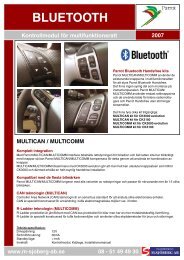
1 2<br />
3 4<br />
5<br />
3<br />
N.B. I dati forniti in questa scheda non sono impegnativi, pertanto devono essere ritenuti solo indicativi ai fini dell’installazione che dovrà essere<br />
eseguita in conformità a quanto riportato nel manuale di installazione del prodotto. Note: This information is not binding, therefore it must be<br />
considered only an example for installation purposes that must be executed as per the instructions given on the product installation manual.<br />
fiscv<strong>10</strong>c
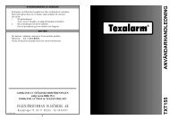
Riferimento D<br />
Reference D<br />
Riferimento C<br />
Reference C<br />
Riferimento B<br />
Reference B<br />
Funzionalità fuori standard da spiegare al cliente per l’utilizzo corretto del sistema:<br />
Non-standard functionality to explain to the end user for daily usage of the system:<br />
1. Se le porte si richiudono automaticamente il sistema si inserisce.<br />
The CDL autorearm, arming the system.<br />
4<br />
N.B. I dati forniti in questa scheda non sono impegnativi, pertanto devono essere ritenuti solo indicativi ai fini dell’installazione che dovrà essere<br />
eseguita in conformità a quanto riportato nel manuale di installazione del prodotto. Note: This information is not binding, therefore it must be<br />
considered only an example for installation purposes that must be executed as per the instructions given on the product installation manual.<br />
6<br />
Riferimento E<br />
Reference E<br />
Riferimento F<br />
Reference F<br />
Riferimento A<br />
Reference A<br />
fiscv<strong>10</strong>c