You also want an ePaper? Increase the reach of your titles
YUMPU automatically turns print PDFs into web optimized ePapers that Google loves.
<strong>MOTORI</strong> <strong>DRIVE</strong>-<strong>AX</strong><br />
<strong>DRIVE</strong>-<strong>AX</strong> <strong>MOTORS</strong>
<strong>DRIVE</strong>-<strong>AX</strong> Pag. 1<br />
ATTENZIONE!<br />
L utilizzo di apparecchiature elettriche ed in particolare<br />
modo di macchine rotanti pu essere estremamente<br />
pericoloso a causa dell elevata tensione di<br />
funzionamento e di alcune parti in rotazione.<br />
L installazione, l uso e la manutenzione di macchine<br />
elettriche deve essere effettuato da personale<br />
competente e qualificato.<br />
E assolutamente necessario, per l utilizzo o<br />
l installazione e la manutenzione di macchine elettriche,<br />
osservare tutte le precauzioni di sicurezza necessarie<br />
al fine di salvaguardare il personale da seri incidenti<br />
anche mortali.<br />
Si raccomanda in particolar modo di rispettare le<br />
seguenti istruzioni:<br />
• evitare ogni contatto con parti sottoposte a tensioni<br />
o con parti in rotazione;<br />
• evitare di rendere inoperanti i dispositivi di sicurezza<br />
e/o protezione;<br />
• assicurarsi che nessun dispositivo collegato all albero<br />
possa mettere in rotazione il rotore;<br />
• verificare, prima di effettuare la manutenzione, che<br />
tutti gli avvolgimenti della macchina siano scollegati<br />
e isolati da tutte le fonti di energia elettrica;<br />
• effettuare una adeguata messa a terra prima<br />
dell inserzione di tensione.<br />
La mancanza di una adeguata messa a terra pu<br />
causare seri danni al personale.<br />
La messa a terra della macchina e di tutte le strutture<br />
relative deve essere eseguita in accordo con le<br />
normative vigenti.<br />
WARNING!<br />
The high operational voltage and the presence of certain<br />
revolving parts can make using electrical equipment,<br />
and particularly revolving machines, extremely<br />
dangerous.<br />
Electrical machines must be installed, used and<br />
maintained by competent and qualified staff.<br />
When using, installing, or carrying out maintenance on<br />
electrical machines, it is essential to take all necessary<br />
safety precautions to protect staff from serious or even<br />
fatal accidents.<br />
You are particularly urged to follow these instructions:<br />
• avoid all contact with voltage-supplied or revolving<br />
parts;<br />
• take care not to disconnect safety and/or protection<br />
devices;<br />
• check that no device connected to the shaft could<br />
cause the rotor to start revolving before carrying out<br />
maintenance work;<br />
• check that all the machine windings have been<br />
disconnected and insulated from all sources of<br />
electrical energy;<br />
• before connection to current make certain that<br />
grounding has been carried out correctly.<br />
Lack of adequate grounding can provoke serious human<br />
injury.<br />
The grounding of the machine and all associated<br />
structures must be carried out according to current<br />
regulations.
Pag. 2 <strong>DRIVE</strong>-<strong>AX</strong>
<strong>DRIVE</strong>-<strong>AX</strong> Pag. 3<br />
INDICE<br />
1. GENERALITA’<br />
1.1. Introduzione<br />
1.2. Identificazione del motore<br />
1.3. Norme di riferimento<br />
2. CARATTERISTICHE COSTRUTTIVE<br />
2.1. Rotore<br />
2.2. Statore<br />
2.3. Avvolgimento statorico<br />
2.4. Sezione motore<br />
2.5. Cuscinetti<br />
2.5.1. Introduzione<br />
2.5.2. Scelta dei cuscinetti: carichi<br />
massimi accettabili<br />
2.6. Forme costruttive<br />
2.7. Ventilazione<br />
2.8. Grado di protezione<br />
2.9. Bilanciatura<br />
2.10. Scatola morsettiera<br />
2.10.1. Generalit<br />
2.10.2. Morsetto di terra<br />
2.10.3. Collegamenti<br />
2.11. Accessori<br />
2.11.1. Generalit<br />
2.11.2. Trasduttore<br />
2.11.3. Freno<br />
3. PRESTAZIONI E MODALITA DI<br />
FUNZIONAMENTO<br />
3.1. Generalit<br />
3.2. Declassamento per temperatura<br />
ambiente e altitudine<br />
3.3. Equivalente termico<br />
3.4. Scelta del motore in funzione<br />
delle caratteristiche di lavoro<br />
3.4.1. Generalit<br />
3.4.2. Funzionamento a coppia<br />
costante<br />
3.4.3. Funzionamento a potenza<br />
costante<br />
4. DATI TECNICI<br />
Pag.<br />
5<br />
5<br />
5<br />
5<br />
6<br />
6<br />
6<br />
6<br />
6<br />
6<br />
6<br />
8<br />
11<br />
12<br />
12<br />
12<br />
12<br />
12<br />
12<br />
13<br />
14<br />
14<br />
14<br />
14<br />
14<br />
14<br />
15<br />
16<br />
16<br />
16<br />
17<br />
19<br />
20<br />
CONTENTS<br />
1. GENERAL<br />
1.1. Introduction<br />
1.2. Motor identification code<br />
1.3. Reference standards<br />
2. CONSTRUCTION<br />
2.1. Rotor<br />
2.2. Stator<br />
2.3. Stator windig<br />
2.4. Motor cross-section<br />
2.5. Bearings<br />
2.5.1. Introduction<br />
2.5.2. Bearings selection:<br />
recommended radial loads<br />
2.6. Mounting form<br />
2.7. Ventilation<br />
2.8. Protection degree<br />
2.9. Balancing<br />
2.10. Terminal box<br />
2.10.1. General<br />
2.10.2. Ground terminal<br />
2.10.3. Connection<br />
2.11. Accessories<br />
2.11.1. General<br />
2.11.2. Transducer<br />
2.11.3. Brake<br />
3. PERFORMANCES AND OPERATING<br />
CHARACTERISTICS<br />
3.1. General<br />
3.2. Power derating for ambient<br />
temperature and altitude<br />
3.3. RMS output power<br />
3.4. Motor selection in function of<br />
application characteristics<br />
3.4.1. General<br />
3.4.2. Operative range at constant<br />
torque<br />
3.4.3. Operative range at constant<br />
power<br />
4. TECHNICAL DATA<br />
Pag.<br />
5<br />
5<br />
5<br />
5<br />
6<br />
6<br />
6<br />
6<br />
6<br />
6<br />
6<br />
8<br />
11<br />
12<br />
12<br />
12<br />
12<br />
12<br />
12<br />
13<br />
14<br />
14<br />
14<br />
14<br />
14<br />
14<br />
15<br />
16<br />
16<br />
16<br />
17<br />
19<br />
20
Pag. 4 <strong>DRIVE</strong>-<strong>AX</strong>
<strong>DRIVE</strong>-<strong>AX</strong> Pag. 5<br />
1. GENERALITA<br />
1.1. Introduzione<br />
I motori asincroni trifase della serie <strong>DRIVE</strong>-<strong>AX</strong> sono<br />
stati progettati per soddisfare i particolari tipi di servizio<br />
richiesti nelle applicazioni industriali dove sono<br />
necessarie alte velocit ed alte prestazioni.<br />
I motori della serie <strong>DRIVE</strong>-<strong>AX</strong> sono costruiti, nelle 6<br />
taglie 63, 80, 100, 132, 160 e 200: le prime due taglie<br />
sono caratterizzate da carcassa in alluminio estruso,<br />
mentre a partire dal 100 lo statore lamellato con pacco<br />
magnetico autoportante.<br />
Le caratteristiche peculiari di questa serie sono:<br />
• elevato rapporto potenza-ingombro<br />
• ottima risposta dinamica alle variazioni di velocit .<br />
• avvolgimenti isolati ed impregnati con<br />
materiali in classe H; classe di sovratemperatura<br />
del motore F.<br />
1.2. Identificazione del motore<br />
La sigla raggruppa le caratteristiche specifiche che<br />
contraddistingue ogni singolo motore riportata in<br />
fig.(1.1).<br />
1.3. Norme di riferimento<br />
I motori della serie <strong>DRIVE</strong>-<strong>AX</strong> sono progettati e costruiti<br />
conformemente alle prescrizioni delle Norme IEC ed<br />
alle Norme armonizzate vigenti nei paesi europei.<br />
CEI 2-3 Italia<br />
VDE 0530 Germania<br />
BS 4999-5000 Regno Unito<br />
NFC 51-111 Francia<br />
Serie del motore<br />
Motor series<br />
Tipo di motore e lunghezza pacco<br />
type of motor and stator lenght<br />
Codice tensione<br />
Voltage code<br />
Codice velocit<br />
Speed code<br />
1. GENERAL<br />
1.1. Introduction<br />
The <strong>DRIVE</strong>-<strong>AX</strong> series three phase induction motors are<br />
designed to satisfy the particular types of industrial<br />
applications where high speed performances are<br />
necessary,<br />
The <strong>DRIVE</strong>-<strong>AX</strong> series includes 6 sizes 63, 80, 100, 132,<br />
160, 200: sizes 63 and 80 size, motors have been<br />
manufactured with extruded aluminium stators, while<br />
from size 100 to 200 have a lamination magnetic body<br />
frame. Especially important on these series are the<br />
following features:<br />
• a very high power/size ratio.<br />
• excellent dynamic response to speed variation.<br />
• windings insulated and potted with class H<br />
materials. Motor temperature rise class F.<br />
1.2. Motor identification<br />
The identification code for each motor includes reference<br />
to the specific characteristics described in fig.(1.1).<br />
1.2. Reference standards<br />
The <strong>DRIVE</strong>-<strong>AX</strong> series motors are designed and<br />
manufactured according to IEC Standards and to<br />
harmonized Standards of the European countries.<br />
CEI 2-3 Italy<br />
VDE 0530 Germany<br />
BS 4999-5000 U. K.<br />
NFC 51-111 France<br />
<strong>DRIVE</strong>-<strong>AX</strong> 100K.3 380 1500<br />
fig.(1.1)
Pag. 6 <strong>DRIVE</strong>-<strong>AX</strong><br />
2. CARATTERISTICHE COSTRUTTIVE<br />
2.1. Rotore<br />
Il rotore del tipo a gabbia di scoiattolo e, normalmente,<br />
realizzato in pressofusione di alluminio: per specifiche<br />
applicazioni, previsto l’utilizzo di barre di rame in luogo<br />
dell’alluminio. Le cave sono inclinate e di forma<br />
appropriata in modo da garantire linearit di<br />
funzionamento anche a bassissima velocit di rotazione.<br />
2.2. Statore<br />
I circuiti magnetici di statore sono ottenuti mediante<br />
impaccaggio, ad elevata pressione, di lamierini magnetici<br />
a bassa perdita e di piccolo spessore isolati su entrambe<br />
le facce: questa scelta permette la progettazione di<br />
motori con un ampio campo di velocit di funzionamento<br />
a coppia costante.<br />
2.3. Avvolgimenti<br />
Le bobine di avvolgimento sono eseguite con filo isolato<br />
in classe H ed impregnate con resine ecologiche speciali<br />
che garantiscono l’adeguata tenuta dielettrica ai picchi<br />
di tensione tipici degli inverter; quando sia previsto un<br />
uso prolungato in ambienti umidi e/o polverosi, questo<br />
isolamento costituisce un ulteriore grado di sicurezza<br />
che si aggiunge al livello di protezione standard (IP54)<br />
del motore.<br />
I collegamenti sono eseguiti con cavi flessibili legati fra<br />
loro da speciali nastri in grado di sopportare elevate<br />
temperature.<br />
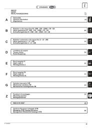
2.4. Sezione motore<br />
La figura (2.1) presenta un motore della serie <strong>DRIVE</strong>-<strong>AX</strong>.<br />
2.5. Cuscinetti<br />
2.5.1. Introduzione<br />
I motori della serie <strong>DRIVE</strong>-<strong>AX</strong> montano, normalmente,<br />
cuscinetti a sfere a doppio schermo autolubrificati: motori<br />
della stessa altezza d’asse e di diversa lunghezza<br />
statorica, adottano gli stessi cuscinetti che sono<br />
dimensionati per il motore con la coppia maggiore.<br />
La vita media dei cuscinetti per motori in forma costruttiva<br />
orizzontale, accoppiati mediante giunto, senza carichi<br />
assiali aggiuntivi di almeno 20,000 ore.<br />
Dall altezza d asse 132, in presenza di tiro cinghia<br />
particolarmente gravoso, previsto, a richiesta,<br />
l adozione di cuscinetto a rulli lato comando.<br />
2. CONSTRUCTION<br />
2.1. Rotor<br />
The rotor is a squirrel cage, usually produced in die cast<br />
aluminium: for specific applications, copper bars are<br />
used instead of aluminium. Slanted slots appropriately<br />
shaped ensure regular running performance even at<br />
extremely low rotation speeds.<br />
2.2. Stator<br />
The stator magnetic circuits are obtained through high<br />
pressure packing of low loss, low thickness magnetic<br />
sheets, insulated on both sides: this solution makes<br />
possible designs of motors with a wide speed range at<br />
constant torque.<br />
2.3. Stator Windings<br />
The winding coils are of class H insulation wiring coated<br />
with ecologic special resins which ensure the adequate<br />
dielectric strength to typical voltage peaks of inverters;<br />
when long working use in damp or dusty environments<br />
is requested, this insulation is a further safety level in<br />
addition to the standard motor protection (IP54)<br />
Connections are made using flexible cables bound<br />
together with special high temperature proof tape.<br />
2.4. Motor cross section<br />
Figure (2.1) shows the cross section drawing of a<br />
<strong>DRIVE</strong>-<strong>AX</strong> series motor.<br />
2.5. Bearings<br />
2.5.1. General<br />
In the <strong>DRIVE</strong>-<strong>AX</strong> series motors double shielded oilless<br />
ball bearings are usually used: motors with the same<br />
shaft heighs but different stator lenghts use the same<br />
bearings dimensioned for the motor with the highest<br />
torque.<br />
For horizontal motors, operating through coupling and<br />
without axial loads, typical bearing life is 20,000 hours<br />
at least.<br />
From the frame size 132 onwards, where belt traction is<br />
particularly hard, roller bearings can be used on request.
<strong>DRIVE</strong>-<strong>AX</strong> Pag. 7<br />
1<br />
2<br />
3<br />
1 Albero<br />
2 Cuscinetto anteriore<br />
3 Scudo anteriore<br />
4 Rotore<br />
5 Statore avvolto<br />
6 Carcassa<br />
7 Scatola morsettiera<br />
8 Cuscinetto posteriore<br />
9 Scudo posteriore<br />
10 Supporto accessori<br />
11 Elettroventilatore<br />
(solo per altezza d'asse 100 - 132 - 160 - 200)<br />
4<br />
Sezione motore <strong>DRIVE</strong>-<strong>AX</strong><br />
<strong>DRIVE</strong>-<strong>AX</strong> motor section<br />
fig.(2.1)<br />
5/6<br />
7<br />
1 Shaft<br />
2 Drive-end bearing<br />
3 Drive-end shield<br />
4 Rotor<br />
5 Wound stator<br />
6 Frame<br />
7 Terminal box<br />
8 Opposite drive-end bearing<br />
9 Opposite drive-end shield<br />
10 Accessories support<br />
11 Electric fan<br />
(only for frame size 100 - 132 - 160 - 200)<br />
8<br />
9<br />
10<br />
11
dove:<br />
Pag. 8 <strong>DRIVE</strong>-<strong>AX</strong><br />
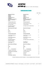
2.5.2. Scelta dei cuscinetti: carichi massimi accettabili<br />
Dopo aver calcolato, in relazione alla potenza ed al<br />
rapporto di trasmissione, la misura della puleggia, si<br />
deve sempre verificare il valore del carico radiale<br />
sull albero, il quale permette di determinare la durata<br />
del cuscinetto anteriore.<br />
Con riferimento alla fig.(2.2), il valore del carico radiale<br />
F r pu essere calcolato con la relazione [2.1], mentre la<br />
durata del cuscinetto anteriore con la relazione [2.2].<br />
L<br />
h<br />
6 ⎛ P ⎞<br />
Fr = 19.5× 10 × ⎜ ⎟ K<br />
⎝ n× D⎠<br />
×<br />
C<br />
n<br />
F Y E<br />
γ<br />
⎡<br />
⎤<br />
⎢<br />
⎥<br />
16. 666<br />
= × ⎢<br />
⎥<br />
⎢ ⎛ ⎞ ⎥<br />
⎢ r × ⎜ + ⎟ + p+ p'⎥<br />
⎣⎢<br />
⎝ B⎠<br />
⎦⎥<br />
[2.1]<br />
[2.2]<br />
F r [N] = carico radiale.<br />
P [KW] = potenza nominale del motore.<br />
n [rpm] = velocit del motore.<br />
D [mm] = diametro primitivo della puleggia.<br />
L h [h] = durata teorica del cuscinetto.<br />
C [N] = carico dinamico del tipo di cuscinetto.<br />
K [-] = coefficiente dipendente dal tipo di cinghia<br />
usata, approssimativamente: K≈1.2 per<br />
cinghia dentata, K≈2.3 per cinghia<br />
trapezoidale, K≈3.8 per cinghia piana.<br />
2.5.2. Bearings selection: recommended radial loads<br />
After the pulley diameter has been calculated according<br />
to the power and transmission ratio, the shaft radial load<br />
must always be checked carefully which allows to<br />
detrmine front bearing life.<br />
Referring to fig.(2.2), the value of the shaft radial load F r<br />
is calculated using the relation [2.1], while bearing life<br />
using the relation [2.2].<br />
L<br />
h<br />
C<br />
n<br />
F Y E<br />
γ<br />
⎡<br />
⎤<br />
⎢<br />
⎥<br />
16. 666<br />
= × ⎢<br />
⎥<br />
⎢ ⎛ ⎞ ⎥<br />
⎢ r × ⎜ + ⎟ + p+ p'⎥<br />
⎣⎢<br />
⎝ B⎠<br />
⎦⎥<br />
B A E<br />
fig.(2.2)<br />
where:<br />
6 ⎛ P ⎞<br />
Fr = 19.5× 10 × ⎜ ⎟ K<br />
⎝ n× D⎠<br />
×<br />
= =<br />
Fr<br />
[2.1]<br />
[2.2]<br />
F r [N] = radial load.<br />
P [KW] = nominal power.<br />
n [rpm] = motor speed.<br />
D [mm] = initial pulley diameter.<br />
L h [h] = theoretical bearing life.<br />
C [N] = bearing dynamic load.<br />
K [-] = coefficient dipending on the type of bekt<br />
used, approximatively: K≈1.2 for cogged<br />
bealt, K≈2.3 for V-belt, K≈3.8 for flat belt.
<strong>DRIVE</strong>-<strong>AX</strong> Pag. 9<br />
Y = rapporto tra i valori (A+B) e B di fig.(2.2)<br />
E [mm] = distanza tra l inizio della sporgenza<br />
d albero del motore ed il punto medio di<br />
applicazione del tiro cinghia fig.(2.2)<br />
p [N] = carico dovuto al rotore.<br />
p [N] = peso del particolare calettato sull albero<br />
(puleggia, volano, ecc.)<br />
γ = costante; γ=3 per cuscinetti standard,<br />
γ=3.33 per cuscinetti a rulli.<br />
Nella tabella di fig.(2.3) sono riportati i parametri per il<br />
calcolo della durata dei cuscinetti; qualora risultassero<br />
valori insufficienti, si consiglia di aumentarli agendo sui<br />
seguenti parametri:<br />
• aumentare il diametro della puleggia.<br />
• adottare cuscinetti a rulli o doppi cuscinetti speciali<br />
• diminuire, ove possibile, il valore di E della formula<br />
[2.2].<br />
MOTORE<br />
C C<br />
CUSCINETTO A<br />
SFERE<br />
BALL BEARING<br />
CUSCINETTO A<br />
RULLI<br />
ROLLER BEARING<br />
Y = ratio between (A+B) and B of fig.(2.2)<br />
E [mm] = distance between the beginning of the<br />
motor shaft and the beltpull application<br />
middle point, see fig.(2.2).<br />
p [N] = rotor load.<br />
p [N] = weight of the component fitted on the<br />
shaft (pulley, handwheel, etc.)<br />
γ = costant; γ=3 for standard bearings,<br />
γ=3.33 for roller bearing.<br />
Data for bearing life calculation are reported in table of<br />
fig.(2.3); should the bearing life result as insufficient, it<br />
is advisable to increase the life period by modifying the<br />
following parameters:<br />
• increasing pulley diameter.<br />
• using roller bearings o special double bearings.<br />
• reducing the value of E, wherever possible, in<br />
formula [2.2].<br />
MOTOR Y B p<br />
63.1C 12,700 - 1.121 165 21<br />
63.2C 12,700 - 1.083 240 35<br />
80.1C 14,000 - 1.121 199 44<br />
80.2C 14,000 - 1.098 244 57<br />
80.3C 14,000 - 1.076 314 78<br />
100K.1 30,700 - 1.212 155 75<br />
100K.2 30,700 - 1.183 180 90<br />
100K.3 30,700 - 1.153 215 115<br />
100K.4 30,700 - 1.124 265 150<br />
100K.5 30,700 - 1.108 305 175<br />
100K.6 30,700 - 1.094 350 210<br />
132K.1 61,800 - 1.162 240 210<br />
132K.2 61,800 - 1.137 285 265<br />
132K.3 61,800 - 1.122 320 315<br />
132K.4 61,800 - 1.1 390 420<br />
132K.5 61,800 - 1.084 460 520<br />
160L.1 81,900 151,000 1.097 427<br />
160L.2 81,900 151,000 1.087 477<br />
160L.3 81,900 151,000 1.077 537<br />
160L.4 81,900 151,000 1.069 597<br />
200L.1 104,000 205,000 1.15 474<br />
200L.2 104,000 205,000 1.138 514<br />
200L.3 104,000 205,000 1.126 564<br />
200L.4 104,000 205,000 1.112 634<br />
fig.(2.3)
Pag. 10 <strong>DRIVE</strong>-<strong>AX</strong><br />
Le tabelle riportate in fig.(2.4) e fig.(2.5) riportano i carichi<br />
massimi sopportabili dai motori, calcolati nell’ipotesi pi<br />
penalizzante di carico sull’estremit del tronco albero.<br />
Tables of fig.(2.4) and fig.(2.5) report the allowable radial<br />
loads the motors can withstand, calculated in the worst<br />
condition of load on the very end of the shaft.<br />
CARICO RADIALE MASSIMO IN [N] CON CUSCINETTO A SFERE LATO ACCOPPIAMENTO<br />
SUGGESTED M<strong>AX</strong>IMUM RADIAL LOAD [N] IN STANDARD <strong>DRIVE</strong> END BALL BEARING VERSION<br />
TAGLIA<br />
SIZE<br />
TIPO<br />
CUSCINETTO<br />
BEARIG<br />
TYPE<br />
VELOCITA’ (giri/min.)<br />
SPEED (rpm)<br />
500 1000 1500 2000 3000 4000 5000 6000 7000 8000 9000<br />
63 6204 2Z C3 1100 850 750 670 600 550 500 480 450 435 415<br />
80 6205 2Z C3 1250 950 850 800 680 620 580 540 500 490 470<br />
100 6208 2Z C3 2200 1700 1500 1350 1150 1050 1000 930 890 850 815<br />
132 6310 2Z C3 3400 2600 2300 2050 1800 1650 1550 1400 1350 - -<br />
160 6312 2Z C3 7000 5450 4750 4250 3700 3350 3100 2900 - - -<br />
200 6314 2Z C3 8700 6750 5900 5250 4600 4150 3850 - - - -<br />
CARICO RADIALE MASSIMO IN [N] CON CUSCINETTO A RULLI LATO ACCOPPIAMENTO<br />
SUGGESTED M<strong>AX</strong>IMUM RADIAL LOAD [N] IN SPECIAL <strong>DRIVE</strong> END BALL BEARING VERSION<br />
TAGLIA<br />
SIZE<br />
TIPO<br />
CUSCINETTO<br />
BEARIG<br />
TYPE<br />
fig.(2.4)<br />
VELOCITA’ (giri/min.)<br />
SPEED (rpm)<br />
500 1000 1500 2000 3000 4000 5000 6000 7000 8000<br />
160 6312 2Z C3 12500 10000 8700 7800 6800 6150 - - - -<br />
200 6314 2Z C3 17000 13200 11500 10300 9000 8000 - - - -<br />
fig.(2.5)
<strong>DRIVE</strong>-<strong>AX</strong> Pag. 11<br />
2.6. Forme costruttive<br />
I motori possono essere forniti solo con una sporgenza<br />
d albero, salvo la sporgenza per l applicazione di<br />
eventuali accessori.<br />
I motori della serie <strong>DRIVE</strong>-<strong>AX</strong> sono normalmente<br />
costruiti in forma IM B3 o in forma IM B5, secondo le<br />
prescrizioni della tabella UNEL 05513 - DIN 42950 -<br />
IEC 34-7 (code I - II) riportate in fig.(2.6).<br />
fig.(2.6)<br />
2.6. Mounting form<br />
Standard motors are provided with one shaft extension,<br />
except where it is necessary to mount eventual<br />
accessories.<br />
<strong>DRIVE</strong>-<strong>AX</strong> series motors are normally manufactured to<br />
IM B3 or IM B5 standards, according to prescription of<br />
UNEL 05513 - DIN 42950 - IEC 34-7 (code I - II), see<br />
fig.(2.6).
Pag. 12 <strong>DRIVE</strong>-<strong>AX</strong><br />
2.7. Ventilazione<br />
I motori della serie <strong>DRIVE</strong>-<strong>AX</strong> sono chiusi senza<br />
ventilazione nelle grandezze 63 e 80; a partire dalla<br />
grandezza 100 previsto un elettroventilatore assiale<br />
posizionato assialmente sul lato opposto accoppiamento.<br />
2.8. Grado di protezione<br />
Tutti i motori sono costruiti con grado di protezione IP54<br />
secondo le IEC 34-5.<br />
La prima cifra caratteristica indica il grado di protezione<br />
contro il contatto con le parti in tensione durante il<br />
funzionamento del motore o le parti in movimento<br />
interne allo stesso e protezione del motore contro la<br />
penetrazione di corpi solidi esterni. La seconda cifra<br />
caratteristica indica il grado di protezione contro la<br />
penetrazione dannosa dell acqua.<br />
In particolare, la prima cifra caratteristica 5 indica<br />
protezione totale contro i contatti con le parti in tensione<br />
o le parti in movimento all interno del motore e la<br />
protezione del motore contro la polvere; la seconda cifra<br />
caratteristica 4 indica la protezione contro gli spruzzi di<br />
acqua.<br />
2.9. Bilanciatura<br />
La bilanciatura del motore effettuata con chiavetta<br />
intera inserita nell’apposita sede; quindi necessario<br />
che gli altri organi calettati sull’albero motore siano al<br />
loro volta bilanciati nel giusto modo.<br />
L’equilibratura normale quella corrispondente al grado<br />
R (ridotta); a richiesta possibile eseguire la bilanciatura<br />
del rotore in grado S (speciale).<br />
2.10. Scatola morsettiera<br />
2.10.1. Generalit<br />
La scatola morsettiera normalmente prevista su tutte<br />
le grandezze in alto. L’uscita cavi in morsettiera.<br />
Per i motori nelle grandezze 63, 80, 100 e 132,<br />
quest’ultimo solo in alcuni casi, prevista la possibilit<br />
di avere la versione con connettore di potenza in<br />
alternativa alla morsettiera, in questo caso il connettore<br />
include anche i contatti dei servizi.<br />
2.10.2. Morsetto di terra<br />
Per tutti i motori previsto, all’interno della scatola<br />
morsettiera, il morsetto di terra completo della targhetta<br />
di identificazione.<br />
2.7. Ventilation<br />
The <strong>DRIVE</strong>-<strong>AX</strong> series motors are totally closed without<br />
ventilation in frame sizes 63 and 80; from frame size<br />
100 are equipped with axial electric fans on the opposite<br />
side to the drive end.<br />
2.8. Protection degree<br />
All motors are manufactured with IP54 protection degree<br />
according to IEC 34-5.<br />
The initial figure indicates protection degree against<br />
contact with all parts connected to main voltage while the<br />
motor is running or with moving parts inside the motor.<br />
and protection of the motor against solid bodies.<br />
The second figure refers to the protection against<br />
damage from water penetration.<br />
In particular, the initial figure 5 refers protection against<br />
contact with parts connected to main voltage while the<br />
motor is running or with moving parts inside the motor<br />
and protection of the motor against dust penetration;<br />
the second figure 4 refers to protection from water spray.<br />
2.9. Balancing<br />
Rotor balancing is carried out with the shaft key inserted<br />
in its keyway; it is essential that the other components<br />
fitted on the motor shaft be correctly balanced as well.<br />
Standard balancing is set according to grade R<br />
(reduced); on request rotor can also be balanced<br />
according to grade S (special).<br />
2.10. Terminal box<br />
2.10.1. General<br />
The terminal box is normally set in the upper position on<br />
all frame sizes. The cable exit is inside the terminal box.<br />
For frame sizes 63, 80, 100 and in special cases also for<br />
132, it is possible to have the power connector version<br />
in which a connector also including all service contacts<br />
is used instead of standard terminal box.<br />
2.10.2. Ground terminal<br />
All motors are provided with one earth terminal: the<br />
ground connection clamp complete with identification<br />
plate is located inside the terminal box.
<strong>DRIVE</strong>-<strong>AX</strong> Pag. 13<br />
2.10.3. Collegamenti<br />
I motori sono normalmente costruiti con tre cavi di<br />
potenza sia in morsettiera che al connettore, come<br />
riportato in fig.(2.7); non , quindi, possibile effettuare<br />
collegamenti per tensioni differenti dalla nominale.<br />
Su richiesta, possibile, solo dopo verifica da parte di<br />
FIMET, la speciale fornitura di motori con collegamenti<br />
a sei o dodici morsetti (solo con morsettiera).<br />
Tutti i motori completi di encoder o resolver sono forniti<br />
con il connettore applicato esternamente alla carcassa<br />
del motore:per i collegamenti al trasduttore consultare<br />
sempre lo schema allegato al motore.<br />
La morsettiera per l’alimentazione del ventilatore assiale,<br />
all’interno della scatola morsettiera oppure i contatti<br />
sono inclusi nel connettore di potenza.<br />
Motore<br />
Motor<br />
M<br />
3 ~<br />
U V W<br />
Freno<br />
Brake<br />
(Optional)<br />
Termoprotettore<br />
Thermal protection<br />
2.10.3. Connections<br />
All motors are normally provided with 3 power cables<br />
connected to the terminal box as well as the connector,<br />
see fig.(2.7), therefore it is not possible to carry out<br />
connections with voltages other than nominal voltage.<br />
On request special motors with 6 or 12 connection<br />
clamps can be custom, but only on FIMET s approval,<br />
and only for terminal box version.<br />
All motors equipped with encoder or resolver are<br />
supplied with connector applied to the exterior of the<br />
motor frame: for transducer connections always see the<br />
connection sheet enclosed with motor.<br />
The terminal board for the axial fan supply is located<br />
inside the terminal box, otherwise, in the power<br />
connector version, are included in the connector<br />
contacts.<br />
CONTRASSEGNI DI COLLEGAMENTO ALLA MORSETTIERA<br />
TERMINAL BOARD CONNECTION MARKS<br />
Rotazione oraria vista lato accoppiamento<br />
Clockwise rotation seen from drive end<br />
FR<br />
PT<br />
Elettroventilatore<br />
Electric fan<br />
F<br />
v
Pag. 14 <strong>DRIVE</strong>-<strong>AX</strong><br />
2.11. Accessori<br />
2.11.1. Generalit<br />
In tutti i motori della serie <strong>DRIVE</strong>-<strong>AX</strong> prevista, di serie,<br />
l applicazione di termoprotettori con temperatura di<br />
intervento a 140¡C –3%, inseriti nell avvolgimento, con<br />
contatti normalmente chiusi. Solo su richiesta, ed<br />
accettazione da parte di FIMET, possibile applicare<br />
altri tipi di rilevatori di temperatura; vedere fig.(2.7).<br />
2.11.2. Trasduttori<br />
E normalmente possibile l applicazione solo di trasduttori<br />
con fissaggio ad albero cavo.<br />
Il rotore del trasduttore direttamente calettato sull albero<br />
motore mentre lo statore fissato direttamente al<br />
coperchio posteriore del motore stesso. Questa tipo di<br />
fissaggio presenta alcuni vantaggi:<br />
• assenza di vibrazioni torsionali tra motore e<br />
trasduttore<br />
• ingombro assiale del motore particolarmente ridotto.<br />
Direttamente calettato al coperchio posteriore del motore<br />
possibile l applicazione di resolver del tipo sempre ad<br />
albero cavo.<br />
2.11.3. Freno<br />
I motori della serie <strong>DRIVE</strong>-<strong>AX</strong> grandezza 63, 80, 100<br />
e 132 possono essere corredati di freno con tensione<br />
normale di alimentazione di 24V.<br />
Nella grandezza 63 e 80, il freno posizionato<br />
posteriormente in posizione protetta, mentre nella<br />
grandezza 100 e 132 posizionato direttamente<br />
all’interno dello statore.<br />
Per eventuale installazioni di freni con caratteristiche<br />
diverse da quelle menzionate nelle schede tecniche.<br />
consultare direttamente FIMET.<br />
3. PRESTAZIONI E MODALITA<br />
DI FUNZIONAMENTO<br />
3.1. Generalit<br />
I motori Serie <strong>DRIVE</strong>-<strong>AX</strong> sono stati progettati per dare<br />
le migliori prestazioni in abbinamento con inverter.<br />
Le prestazioni nominali dei motori indicate nelle schede<br />
tecniche, sono riferite a tensioni di alimentazione di<br />
nominali riportate, le velocit massime a potenza<br />
costante riferite ad alimentazione a tensione costante:<br />
avvolgimenti per tensioni speciali sono disponibili su<br />
richiesta.<br />
2.11. Accessories<br />
2.11.1. General<br />
All <strong>DRIVE</strong>-<strong>AX</strong> series motors are equipped with a<br />
standard heat protection system with intervention at<br />
140¡C –3%, inserted in the winding coil, with contacts<br />
normally set in closed position. Other types of heat<br />
detectors can be installed on request, but only after<br />
FIMET s approval; see fig.(2.7).<br />
2.11.2. Transducers<br />
Normally, only hollow shaft mounted transducers can<br />
be fitted on <strong>DRIVE</strong>-<strong>AX</strong> series motors.<br />
The transducer rotor is fitted directly onto the motor<br />
shaft is fixed directly to the rear motor cover. This type<br />
of attachement provides the following advantages:<br />
• absence of torsional vibration between motor and<br />
transducer<br />
• motor axial dimension really small.<br />
An hollow shaft resolver can be fitted directly on the<br />
rear motor cover.<br />
2.11.3. Brake<br />
The <strong>DRIVE</strong>-<strong>AX</strong> series motor frame sizes 63, 80, 100,<br />
132 can be equipped with brake with standard supply<br />
24V .<br />
On frame sizes 63 and 80, brake is placed at the rear in<br />
a protected position, while on frame sizes 100 and 132<br />
it is placed directly inside the stator.<br />
For the istallation of any brake types not included in the<br />
specifications in this manual, please contact FIMET for<br />
advice.<br />
3. PERFORMANCES AND OPERATING<br />
CHARACTERISTICS<br />
3.1. General<br />
The <strong>DRIVE</strong>-<strong>AX</strong> series motors are designed to do best<br />
performances supplied by inverter.<br />
Nominal performances of motors reported in data sheets<br />
are referred to reported nominal supply, maximum speed<br />
at costant power are referred to costant supply voltage:<br />
special winding for not standard supply voltage are<br />
available on request.
<strong>DRIVE</strong>-<strong>AX</strong> Pag. 15<br />
In ogni applicazione specifica molto importante la<br />
scelta del tipo di motore e del tipo di avvolgimento al<br />
fine di ottimizzare il rapporto costo/prestazioni del<br />
motore.<br />
Nella scelta necessario tenere presente:<br />
• l’ambiente in cui si trover il motore e considerare<br />
eventuali declassamenti dovuti alla temperatura ed<br />
all’altitudine;<br />
• il ciclo di lavoro richiesto per assicurare che la<br />
sovratemperatura si mantenga entro i limiti della<br />
classe termica di appartenenza;<br />
• le prestazioni massime richieste, anche se per brevi<br />
periodi, e cio , tipicamente, sovraccarico massimo,<br />
deflussamento a potenza costante, velocit massima<br />
assoluta.<br />
La metodologia sopra presentata permette di fare una<br />
scelta ottimale del motore; nei prossimi paragrafi verr<br />
fatta una trattazione teorica semplificata, nella quale<br />
non si terr sempre conto di tutti gli aspetti -reattanze di<br />
dispersione, perdite, ecc.ecc.- atta a consentire una<br />
prima scelta del motore: per applicazioni complesse si<br />
suggerisce di contattare FIMET per un preventivo.<br />
3.2. Declassamento per temperatura ambiente ed<br />
altitudine<br />
I declassamenti di potenza da effettuare al variare della<br />
temperatura dell’aria e dell’altitudine si ricavano dal<br />
grafico di fig.(3.1)<br />
Potenza %<br />
Power %<br />
110<br />
100<br />
90<br />
80<br />
70<br />
60<br />
50<br />
40°C<br />
50°C<br />
60°C<br />
1000<br />
2000<br />
fig.(3.1)<br />
In every application it is very important the selection of<br />
the motor and of the right winding code in order to obtain<br />
the best ratio cost/performances.<br />
To select the motor it must be considered:<br />
• the enviroment in which the motor works and<br />
consequent power derating owing to temperature<br />
and altitude ;<br />
• the duty cycle requested to ensure that<br />
overtemperature of the motoer keeps within its<br />
thermal class limits;<br />
• maximum performances requested, even though<br />
for short periods,that is, maximum overload, flux<br />
weakening speed range at constant power, absolute<br />
maximum speed.<br />
This general methodology allows a good selection of<br />
the motor; next paragraphs will show a simplified<br />
theoretical treatment, in which not all physical aspects<br />
will consider -winding leakage reactance, losses, etc.and<br />
that allows the first motor selection : when complex<br />
application are required, it is recommended to contact<br />
FIMET for a quotation.<br />
3.2. Power derating for ambient temperature and<br />
altidude<br />
Power deratings for temperature or altitude variation,<br />
are reported in the diagram of fig.(3.1)<br />
30°C<br />
3000<br />
4000<br />
m
Pag. 16 <strong>DRIVE</strong>-<strong>AX</strong><br />
3.3. Equivalente termico<br />
L’equivalente termico viene calcolato, come sui motori<br />
in corrente continua, a partire dal ciclo di lavoro,<br />
mediante la seguente formula, e serve a determinare<br />
la potenza in servizio S1 che deve erogare il motore<br />
per poter eseguire il ciclo di lavoro richiesto senza<br />
superare la sovratemperatura relativa alla propria classe<br />
di isolamento:<br />
dove<br />
P<br />
eq<br />
=<br />
K<br />
∑<br />
i= 1<br />
(P) i t<br />
2 i<br />
[3.1]<br />
P eq [W] = potenza equivalente<br />
P i [W] = potenza nei vari intervalli del ciclo di<br />
lavoro<br />
t i [sec] = intervalli di tempo<br />
T [sec] = tempo totale<br />
3.4. Scelta del motore in funzione delle<br />
caratteristiche di lavoro<br />
3.4.1. Generalit<br />
Normalmente il funzionamento di un motore asincrono<br />
alimentato da inverter schematizzato dal diagramma<br />
di fig.(3.2), nel quale sono presenti due zone ben distinte:<br />
• la zona A di funzionamento a coppia costante<br />
• la zona B di funzionamento a potenza costante<br />
Nella zona A, che va da 0 fino alla velocit nominale, il<br />
motore viene alimentato con una tensione proporzionale<br />
alla frequenza: i motori della serie <strong>DRIVE</strong>-<strong>AX</strong> sono<br />
servoventilati e quindi sono in grado di fornire la coppia<br />
nominale costantemente fino a velocit bassissime.<br />
Nella zona B, oltre la velocit nominale, il motore lavora<br />
in deflussamento con coppia decrescente con<br />
l aumentare della velocit .<br />
T<br />
Potenza<br />
Power<br />
A<br />
Velocità nominale<br />
Nominal speed<br />
B<br />
fig.(3.2)<br />
3.3. RMS output power<br />
The RMS output power is determined, as for DC motors,<br />
considering the duty cycle, with the following formula,<br />
and determines the power in duty S1 of the motor<br />
necessary to perform the requested duty cycle without<br />
overising temperature of the motor insulation class:<br />
where<br />
P<br />
eq<br />
=<br />
i= 1<br />
(P) i t<br />
2 i<br />
P eq [W] = RMS output power<br />
P i [W] = power in different intervals<br />
t i [sec] = time interval<br />
T [sec] = total time<br />
K<br />
∑<br />
T<br />
[3.1]<br />
3.4. Motor selection in function of application<br />
characteristics<br />
3.4.1. General<br />
Normally, operating mode of an asyncronous induction<br />
motor supplied by inverter can be shown in the diagram<br />
of fig.(3.2), in which two different zones:<br />
• an operating constant torque zone: A<br />
• an operating constant power zone: B<br />
In the A zone, speed range from 0 to nominal speed,<br />
the motor is supplied with voltage proportional to<br />
frequency: <strong>DRIVE</strong>-<strong>AX</strong> series motors are servo assisted<br />
ventilated, then are be able to operate with nominal<br />
constant torque also at very low speed.<br />
In the B zone, over nominal speed range, motor flux is<br />
reduced and the motor operates with torque decreasing<br />
with speed.<br />
Velocità<br />
Speed
<strong>DRIVE</strong>-<strong>AX</strong> Pag. 17<br />
3.4.2. Funzionamento a coppia costante<br />
Nell’intervallo da 0 alla velocit nominale, il motore<br />
generalmente alimentato con un tensione ai morsetti<br />
che proporzionale alla frequenza di alimentazione e,<br />
quindi, alla velocit di sincronismo. In questo intervallo<br />
il flusso al traferro del motore, in prima approssimazione,<br />
trascurando le cadute di tensione statoriche e le<br />
induttanze di dispersione, praticamente costante:<br />
dove:<br />
Φ [Wb] = flusso al traferro del motore<br />
V [V] = tensione di alimentazione motore<br />
f [Hz] = frequenza di alimentazione<br />
K [-] = costante dipendente dal motore<br />
Ora, si ha che:<br />
dove:<br />
C [Nm] = coppia fornita<br />
i r [A] = corrente rotorica<br />
e<br />
dove:<br />
i<br />
V<br />
C i C<br />
f i<br />
≈ ⇒ ≈ Φ<br />
r<br />
=<br />
r r<br />
Er [V] = forza elettromotrice indotta nel rotore<br />
Rr [W]= resistenza rotorica<br />
Lr [H] = induttanza di dispersione rotorica<br />
s = scorrimento percentuale<br />
[3.2]<br />
[3.3]<br />
[3.4]<br />
per valori di s piccoli -come quelli che si hanno in<br />
presenza di carichi nominali - si pu dire che:<br />
per cui<br />
Φ= ⎛ ⎞<br />
K⎜ ⎟<br />
⎝ ⎠<br />
V<br />
f<br />
E<br />
2<br />
R r + (2π fsL r)<br />
r<br />
2<br />
2 2<br />
r r<br />
r<br />
2<br />
R + (2π fsL ) ≅R<br />
i<br />
r<br />
Er<br />
=<br />
Rr<br />
V<br />
a sua volta Er≈ W( ∆s) Φ ≈ W( ∆s)<br />
f<br />
[3.5]<br />
[3.6]<br />
[3.7]<br />
3.4.2. Operative range at constant torque<br />
In the range from 0 to nominal speed, the motor is<br />
generally supplied by a voltage proportional to frequency,<br />
that is proportional to syncronous speed.<br />
In this speed range, the motor flux, overlooking stator<br />
voltage drops and stator winding leakage inductance, is<br />
nearly constant:<br />
where:<br />
Φ [Wb] = motor flux<br />
V [V] = motor supply voltage<br />
f [Hz] = supply frequency<br />
K [-] = constant depending on motor<br />
Now we have:<br />
where:<br />
C [Nm] = motor torque<br />
i r [A] = rotor current<br />
and<br />
where:<br />
i<br />
r<br />
V<br />
C i C<br />
f i<br />
≈ ⇒ ≈ Φ<br />
=<br />
r r<br />
Er [V] = rotor induced voltage<br />
Rr [W]= rotor resistance<br />
Lr [H] = rotor leakage inductance<br />
s = percentage slip<br />
[3.2]<br />
[3.3]<br />
[3.4]<br />
for low s -as operating mode with nominal load - we<br />
have:<br />
and then<br />
with<br />
Φ= ⎛ ⎞<br />
K⎜ ⎟<br />
⎝ ⎠<br />
V<br />
f<br />
E<br />
2<br />
R r + (2π fsL r)<br />
r<br />
2<br />
2 2<br />
r r<br />
r<br />
2<br />
R + (2π fsL ) ≅R<br />
i<br />
r<br />
Er<br />
=<br />
Rr<br />
V<br />
Er≈ W( ∆s) Φ ≈ W( ∆s)<br />
f<br />
[3.5]<br />
[3.6]<br />
[3.7]
Pag. 18 <strong>DRIVE</strong>-<strong>AX</strong><br />
dove:<br />
W [-] = costante<br />
∆ s [rpm] = scorrimento assoluto<br />
quindi:<br />
per cui<br />
V<br />
ir≈W(∆s) Rf r<br />
( ∆s)<br />
( V)<br />
C =<br />
Rr<br />
f<br />
[3.8]<br />
[3.9]<br />
supponendo la resistenza di rotore costante, e poich<br />
il motore non deve superare il regime termico,<br />
necessario tenere lo scorrimento assoluto costante,<br />
quindi:<br />
( )<br />
2<br />
( ∆s)<br />
V<br />
C = = COST.<br />
Rr<br />
f<br />
[3.10]<br />
In realt , lo scorrimento assoluto non rimane costante<br />
a mano a mano che il motore si riscalda, per almeno<br />
due ragioni:<br />
• poich aumenta la resistenza di statore, c’ una<br />
maggior caduta di tensione e, quindi, la V utile a<br />
determinare il flusso diminuisce e quindi diminuisce<br />
il flusso che nella [3.2] proporzionale a (V/f).<br />
• poich la resistenza di rotore aumenta con il<br />
riscaldarsi del motore il denominatore R r aumenta.<br />
Perci , a coppia nominale, il motore, passando da freddo<br />
a caldo, avr uno scorrimento assoluto maggiore.<br />
Da ultimo, per quanto riguarda la zona A di<br />
funzionamento a coppia costante, ricordiamo che,<br />
diminuendo la velocit , si diminuiscono tensione e<br />
frequenza di alimentazione: a parit di corrente assorbita<br />
dal motore, si ha una caduta di tensione statorica R si s<br />
costante che, proporzionalmente, "pesa" di pi a bassa<br />
velocit , cio con tensioni basse.<br />
Per questa ragione, utilizzando, per esempio, un motore<br />
avvolto per una velocit nominale di 2000rpm, pu<br />
essere utile, se lo si fa lavorare a 500rpm, impostare<br />
sull’inverter un leggero "boost", a bassa velocit , sulla<br />
tensione di alimentazione del motore.<br />
2<br />
where:<br />
W [-] = constant<br />
∆ s [rpm] = absolute slip<br />
then:<br />
therefore<br />
V<br />
ir≈W(∆s) Rf r<br />
( ∆s)<br />
( V)<br />
C =<br />
Rr<br />
f<br />
[3.8]<br />
[3.9]<br />
if we suppose constant the rotor resistance, and because<br />
the motor must not exceed nominal thermal rate,<br />
absolute slip must be mantained constant, and then:<br />
( )<br />
2<br />
( ∆s)<br />
V<br />
C = = COST.<br />
Rr<br />
f<br />
[3.10]<br />
Actually, while the motor increases its temperature,<br />
absolute slip do not remain constant for two reasons:<br />
• since the stator resistance increases, there is more<br />
voltage drop and, so, the voltage V, which<br />
determines flux, decreases and consequently, the<br />
flux in [3.2], which is proportional to (V/f), decreases.<br />
• since the rotor resistance increases with<br />
temperature, the denominator R r increases.<br />
So, at nominal torque, increasing its temperature, the<br />
motor will have an higher absolute slip.<br />
In the A zone at constant torque, decreasing the speed,<br />
supply voltage and frequency decrease: at a parity of<br />
motor current, being the stator drop voltage R si s constant,<br />
this has a more relevant effect at low speed, that is at<br />
low voltage.<br />
For this reason, for a motor with nominal speed of 2000<br />
rpm, which operates at 500 rpm for a long time, it could<br />
be useful to set a voltage "boost" at low speed.<br />
2
<strong>DRIVE</strong>-<strong>AX</strong> Pag. 19<br />
3.4.3. Funzionamento a potenza costante<br />
Nella zona B il motore lavora con una coppia che varia<br />
in modo inversamente proporzionale alla velocit , cio :<br />
C C f ⎛ n⎞<br />
= n⎜<br />
⎟<br />
⎝ f ⎠<br />
[3.11]<br />
3.4.3. Operative range at constant power<br />
In the B zone the motor operates with a torque which ,<br />
varies as 1/f, that is:<br />
C C f ⎛ n⎞<br />
= n⎜<br />
⎟<br />
⎝ f ⎠<br />
se riconsideriamo la [3.2] Φ=<br />
mantenendo la tensione costante, il flusso avrebbe un<br />
andamento inversamente proporzionale alla frequenza;<br />
in realt , nella zona B, la caduta di tensione statorica<br />
dovuta alla reattanza di dispersione (ωLi), non pi<br />
trascurabile e l’effetto di smagnetizzazione dovuto alle<br />
correnti di rotore rendono la [3.2] non pi utilizzabile: di<br />
fatto, con l’aumentare della frequenza di alimentazione,<br />
a tensione costante, si ha una riduzione del flusso al<br />
traferro molto pi grande della legge di proporzionalit<br />
inversa.<br />
Questa condizione quella che si presenta,<br />
normalmente, con l’utilizzo di inverter tradizionali (non<br />
vettoriali).<br />
Se, invece, si sceglie un motore avvolto per un tensione<br />
nominale inferiore a quella massima dell’inverter, nella<br />
zona di deflussamento la tensione sul motore potr<br />
essere aumentata, a mano a mano che il motore supera<br />
la velocit nominale, e quindi, potranno essere<br />
compensati in parte gli effetti dovuti all’induttanza di<br />
dispersione e di smagnetizzazione dovuto alle correnti<br />
rotoriche, migliorando cos le prestazioni del motore in<br />
deflussamento.<br />
Di contro, dovr essere scelto un inverter con corrente<br />
nominale maggiore. Infatti, si supponga di avere scelto<br />
un motore che a 380V/50Hz assorbe 100A nominali, e<br />
quindi necessita di un inverter da 380V in uscita e circa<br />
100A<br />
Ora, per migliorare le prestazioni in deflussamento si<br />
cambi tipo di avvolgimento e si scelga lo stesso motore<br />
ma a 290V/50Hz: ovviamente la corrente nominale sar<br />
maggiore, diciamo circa 130A: perci si dovr utilizzare<br />
un inverter da 380V in uscita e 130A nominali, quindi<br />
di taglia maggiore del precedente.<br />
I dati di deflussamento dei motori <strong>DRIVE</strong>-<strong>AX</strong> riportati<br />
nel presente catalogo sono comunque riferiti ad<br />
alimentazione a tensione costante pari a quella<br />
nominale.<br />
⎛ ⎞<br />
K⎜ ⎟<br />
⎝ ⎠<br />
V<br />
f<br />
if we consider the [3.2] Φ=<br />
voltage, flux would varies as 1/f; actually, in the B zone,<br />
the stator voltage drop voltage owing to leakage<br />
reactance (ωLi) no more negligible and the field weaking<br />
caused by the rotor current make the [3.2] not ever<br />
usable: at constant voltage, the flux is actually reduced<br />
much more than 1/f.<br />
This situation normally happens with standard inverters,<br />
(not vectrol controlled).<br />
On the contrary, if a motor with a winding for a voltage<br />
lower than the maximum inverter voltage output is<br />
selected, since the motor exceeds the nominal speed in<br />
the weaking flux zone, the motor voltage will be able to<br />
be increased, so that the effects of leakage stator<br />
reactance and of rotor current will be reduced and the<br />
performances of the motor will get better.<br />
In this case an inverter with an higher nominal current<br />
must be selected. For example, suppose to select a<br />
380/50Hz motor 100A nominal current; this motor needs<br />
a 380V inverter with a nominal current of minimum 100A.<br />
Now, to increase performances in weaking flux zone<br />
select the same type of motor but 290V/50Hz: naturally<br />
nominal current will be higher, near 130A: so it will be<br />
necessary to use an inverter 380V output and with<br />
nominal current of 130A, bigger than the first one.<br />
With reference to the weaking flux zone, all <strong>DRIVE</strong>-<strong>AX</strong><br />
series motor data reported in the technical scheets of<br />
next pages are referred to constant voltage equal to<br />
nominal voltage.<br />
⎛ ⎞<br />
K⎜ ⎟<br />
⎝ ⎠<br />
V<br />
risulta che,<br />
f<br />
with constant<br />
[3.11]
Pag. 20 <strong>DRIVE</strong>-<strong>AX</strong><br />
4. DATI TECNICI<br />
Le successive schede tecniche contengono le<br />
caratteristiche elettriche fondamentali dei motori serie<br />
<strong>DRIVE</strong>-<strong>AX</strong> con le seguenti precisazioni:<br />
• alimentazione da inverter standard PWM.<br />
• ventilazione mediante elettroventilatore separato.<br />
• temperatura dell’aria di raffreddamento non superiore<br />
ai 40¡C.<br />
• Potenza nominale in S1; sovraccarico in servizio<br />
S6/40% con ciclo di lavoro tale da conservare<br />
l’equivalente termico.<br />
• Corrente nominale assorbita dal motore con una<br />
tensione di alimentazione ai morsetti come indicato<br />
nelle rispettive colonne.<br />
• Velocit massima a potenza costante riferita a<br />
deflussamento con tensione di alimentazione pari<br />
a quella nominale del motore, non incrementata<br />
durante il deflussamento stesso.<br />
4. TECHNICAL DATA<br />
Next technical data scheets show main electrical<br />
parameters of <strong>DRIVE</strong>-<strong>AX</strong> series motors with this<br />
statement:<br />
• Supply by PWM standard inverter.<br />
• Ventilation by separated electric fan.<br />
• Cooling air temperature not exceeding 40¡C.<br />
• Nominal power in S1; overload in duty S6/40% with<br />
duty cycle RMS current not exceeding the nominal<br />
temperature.<br />
• Motor nominal current referred to voltage supply as<br />
reported in respective columns.<br />
• Maximum speed at constant power in weaking flux<br />
zone referred to constant voltage supply equal to<br />
nominal voltage, not increased while weaking flux.
<strong>DRIVE</strong>-<strong>AX</strong> Pag. 21<br />
SCHEDE TECNICHE <strong>MOTORI</strong><br />
MOTOR DATA SHEETS
63.1C<br />
63.2C<br />
VELOCITA NOMINALE<br />
Pag. 22 <strong>DRIVE</strong>-<strong>AX</strong> SERIES MOTOR CATALOGUE<br />
<strong>DRIVE</strong>-<strong>AX</strong> 63 4poli<br />
NOMINAL SPEED<br />
COPPIA NOMINALE<br />
NOMINAL TORQUE<br />
POTENZA NOMINALE<br />
DATI GENERALI - GENERAL DATA<br />
Forma costruttiva - Mounting B5 - B3/B5 su richiesta B3/B5 on request Isolamento - Insulation<br />
Classe F - Class F<br />
Equilibratura - Balancing<br />
grado R - R degree (ISO 2373)<br />
Raffreddamento - Cooling system Non ventilato<br />
Protezione - Protection<br />
IP54<br />
T. amb./Altitud.- Amb. temp./Altitud. 0 - 40¡C/1000m SLM - 1000m AS<br />
Protezione termica - Thermal prot. Klixon NC (250V - 2.5A)<br />
Trasduttore - Transducer<br />
Encoder o Resolver - Encoder or Resolver<br />
DATI TECNICI - TECHNICAL DATA<br />
SERVIZIO S1 - DUTY S1<br />
NOMINAL POWER<br />
TENSIONE NOMINALE COD.38<br />
NOMINAL VOLTAGE COD.38<br />
CORRENTE NOMINALE COD.38<br />
NOMINAL CURRENT COD.38<br />
TENSIONE NOMINALE COD.33<br />
NOMINAL VOLTAGE COD.33<br />
CORRENTE NOMINALE COD.33<br />
NOMINAL CURRENT COD.33<br />
VELOCITA MASSIMA A POTENZA<br />
COSTANTE<br />
M<strong>AX</strong>IMUM SPEED AT CONSTANT<br />
POWER<br />
SERV. S6/40% - DUTY S6/40%<br />
FIMET ITALIA ¥ Viale Rimembranze,37 - 12042 BRA (CN) ¥Tel. +39 (0) 172 438411 ¥Fax +39 (0) 172 421367 ¥Http:www.fimet.com ¥E - mail:fimet@fimet.com<br />
POTENZA NOMINALE<br />
NOMINAL POWER<br />
CORRENTE NOMINALE COD.38<br />
NOMINAL CURRENT COD.38<br />
CORRENTE NOMINALE COD.33<br />
NOMINAL CURRENT COD.33<br />
VELOCITA MASSIMA A POTENZA<br />
COSTANTE<br />
M<strong>AX</strong>IMUM SPEED AT CONSTANT<br />
POWER<br />
RPM Nm KW V A V A RPM Nm KW A A RPM Kgm 2 RPM<br />
1000 2.60 0.27 380 0.9 330 1.0 2500 3.66 0.38 1.3 1.5 2000 0.0017 9500<br />
1500 2.55 0.40 380 1.3 330 1.5 3000 3.57 0.55 1.8 2.1 2500 0.0017 9500<br />
2000 2.50 0.50 380 1.8 330 2.1 4000 3.50 0.73 2.6 3.0 3500 0.0017 9500<br />
3000 2.40 0.75 380 2.6 330 3.0 5500 3.20 1.00 3.5 3.8 4500 0.0017 9500<br />
4000 2.10 0.90 380 3.3 330 3.8 7500 2.95 1.25 4.6 5.3 6000 0.0017 9500<br />
1000 4.80 0.50 380 1.7 330 1.9 2500 6.70 0.70 2.3 2.7 2000 0.0020 9500<br />
1500 4.80 0.75 380 2.5 325 2.9 3000 6.70 1.05 3.5 4.1 2500 0.0020 9500<br />
2000 4.80 1.00 380 3.3 330 3.8 4000 6.70 1.40 4.6 5.3 3500 0.0020 9500<br />
3020 4.50 1.41 380 4.9 325 5.7 5500 6.30 2.00 6.9 8.1 4500 0.0020 9500<br />
4000 3.90 1.63 380 6.4 320 7.6 7500 5.44 2.25 8.8 10.5 6000 0.0020 9500<br />
COPPIA NOMINALE<br />
NOMINAL TORQUE<br />
INERZIA ROTORE<br />
ROTOR INERTIA<br />
VELOCITA MASSIMA ASSOLUTA<br />
ABSOLUTE M<strong>AX</strong>IMUM SPEED
ø 110 j6<br />
M 5<br />
CATALOGO <strong>MOTORI</strong> SERIE <strong>DRIVE</strong>-<strong>AX</strong> Pag. 23<br />
3.5<br />
<strong>DRIVE</strong>-<strong>AX</strong> 63 4poles<br />
40 40<br />
13<br />
B<br />
O<br />
Superficie Montaggio Accessori<br />
Accessories Mounting Surface<br />
q<br />
O<br />
Freno<br />
Brake<br />
110<br />
∼20<br />
Trasduttore*<br />
Transducer *<br />
FIMET ITALIA ¥ Viale Rimembranze,37 - 12042 BRA (CN) ¥Tel. +39 (0) 172 438411 ¥Fax +39 (0) 172 421367 ¥Http:www.fimet.com ¥E - mail:fimet@fimet.com<br />
∼70<br />
∼50<br />
-0,5<br />
63 120<br />
Trasduttore*<br />
Transducer *<br />
PG 16<br />
(*): il disegno rappresenta il trasduttore tipo ELCIS 7210; per gli altri tipi di trasduttori prevista una<br />
apposita copertura di protezione.<br />
(*): the draw shows ELCIS 7210 transducer; for other types of transducers a special protection cover is foreseen.<br />
FRENO - BRAKE<br />
Tipo 06 Tipo 08<br />
Coppia statica Static torque [Nm] 4 8<br />
Momento d’inerzia Moment of inertia [Kgcm 2 ] 0.13 0.45<br />
Massima velocit di frenatura Maximum braking speed rpm 3,000 3,000<br />
Massima velocit assoluta Absolute maximum speed rpm 12,400 12,400<br />
Potenza assorbita Input power [W] 20 25<br />
Alimentazione Power supply [VDC] 24 24<br />
VERSIONE NORMALE VERSIONE CON FRENO<br />
STANDARD VERSION VERSION WITH BRAKE<br />
Motore - Motor q B O Peso Kg O Peso Kg<br />
63.1C 133 100 220 11 267 13<br />
63.2C 208 175 295 15 342 17<br />
ø 7<br />
21,5<br />
CUSCINETTI - BEARINGS<br />
Cuscinetto a sfere<br />
Ball bearing<br />
110<br />
100<br />
125<br />
6<br />
19 j6<br />
6<br />
ø 8,5<br />
Cuscinetto a rulli<br />
Roller bearing<br />
Lato comando Drive end 6204 2Z C3 -<br />
Lato opposto comando Opposite drive end 6203 2Z C3 -<br />
ø 160<br />
ø 130
80.1C<br />
80.2C<br />
80.3C<br />
VELOCITA NOMINALE<br />
Pag. 24 <strong>DRIVE</strong>-<strong>AX</strong> SERIES MOTOR CATALOGUE<br />
<strong>DRIVE</strong>-<strong>AX</strong> 80 4poli<br />
NOMINAL SPEED<br />
COPPIA NOMINALE<br />
NOMINAL TORQUE<br />
POTENZA NOMINALE<br />
DATI GENERALI - GENERAL DATA<br />
Forma costruttiva - Mounting B5 - B3/B5 su richiesta B3/B5 on request Isolamento - Insulation<br />
Classe F - Class F<br />
Equilibratura - Balancing<br />
grado R - R degree (ISO 2373)<br />
Raffreddamento - Cooling system Non ventilato<br />
Protezione - Protection<br />
IP54<br />
T. amb./Altitud.- Amb. temp./Altitud. 0 - 40¡C/1000m SLM - 1000m AS<br />
Protezione termica - Thermal prot. Klixon NC (250V - 2.5A)<br />
Trasduttore - Transducer<br />
Encoder o Resolver - Encoder or Resolver<br />
DATI TECNICI - TECHNICAL DATA<br />
SERVIZIO S1 - DUTY S1<br />
NOMINAL POWER<br />
TENSIONE NOMINALE COD.38<br />
NOMINAL VOLTAGE COD.38<br />
CORRENTE NOMINALE COD.38<br />
NOMINAL CURRENT COD.38<br />
TENSIONE NOMINALE COD.33<br />
NOMINAL VOLTAGE COD.33<br />
CORRENTE NOMINALE COD.33<br />
NOMINAL CURRENT COD.33<br />
VELOCITA MASSIMA A POTENZA<br />
COSTANTE<br />
M<strong>AX</strong>IMUM SPEED AT CONSTANT<br />
POWER<br />
SERV. S6/40% - DUTY S6/40%<br />
FIMET ITALIA ¥ Viale Rimembranze,37 - 12042 BRA (CN) ¥Tel. +39 (0) 172 438411 ¥Fax +39 (0) 172 421367 ¥Http:www.fimet.com ¥E - mail:fimet@fimet.com<br />
COPPIA NOMINALE<br />
NOMINAL TORQUE<br />
POTENZA NOMINALE<br />
NOMINAL POWER<br />
CORRENTE NOMINALE COD.38<br />
NOMINAL CURRENT COD.38<br />
CORRENTE NOMINALE COD.33<br />
NOMINAL CURRENT COD.33<br />
VELOCITA MASSIMA A POTENZA<br />
COSTANTE<br />
M<strong>AX</strong>IMUM SPEED AT CONSTANT<br />
POWER<br />
RPM Nm KW V A V A RPM Nm KW A A RPM Kgm 2 RPM<br />
1000 7.0 0.73 380 1.8 330 2.1 2500 9.5 1.00 2.5 2.9 1200 0.0029 9000<br />
1500 7.0 1.10 380 2.7 330 3.1 3000 9.5 1.50 3.7 4.2 1800 0.0029 9000<br />
2000 7.0 1.40 380 3.7 325 4.3 3800 9.5 2.00 5.3 6.3 2500 0.0029 9000<br />
3000 6.4 2.00 380 5.1 325 6.0 4800 8.9 2.80 7.1 8.3 3500 0.0029 9000<br />
4000 5.9 2.45 380 6.8 325 8.0 5000 8.2 3.40 9.4 11.0 4500 0.0029 9000<br />
1000 9.6 1.00 380 2.5 330 2.9 2700 13.4 1.40 3.4 3.9 1400 0.004 9000<br />
1500 9.6 1.50 380 3.7 330 4.2 3200 13.4 2.00 4.8 5.5 2000 0.004 9000<br />
2000 9.6 2.00 380 5.0 325 5.8 4000 13.0 2.70 6.6 7.7 2700 0.004 9000<br />
3000 8.7 2.70 380 7.2 325 8.4 5000 11.8 3.70 9.8 11.5 3700 0.004 9000<br />
4000 8.1 3.40 380 9.2 330 10.6 5500 11.0 4.60 12.4 14.3 4600 0.004 9000<br />
1000 13.4 1.40 380 3.2 330 3.7 2800 18.0 1.9 4.4 4.4 1500 0.0058 9000<br />
1500 13.4 2.10 380 4.9 325 5.6 3300 18.0 2.8 6.5 6.5 2200 0.0058 9000<br />
2000 13.4 2.80 380 6.6 340 7.6 4200 18.0 3.8 8.8 8.8 2800 0.0058 9000<br />
2950 12.1 3.80 380 9.3 325 10.7 5000 17.0 5.3 12.8 12.8 3800 0.0058 9000<br />
4140 11.6 5.00 380 12.8 340 13.9 6000 15.8 6.8 16.5 16.5 4800 0.0058 9000<br />
INERZIA ROTORE<br />
ROTOR INERTIA<br />
VELOCITA MASSIMA ASSOLUTA<br />
ABSOLUTE M<strong>AX</strong>IMUM SPEED
ø 130 j6<br />
M 8<br />
CATALOGO <strong>MOTORI</strong> SERIE <strong>DRIVE</strong> <strong>AX</strong> Pag. 25<br />
3.5<br />
<strong>DRIVE</strong>-<strong>AX</strong> 80 4poles<br />
14<br />
50<br />
50<br />
Superficie Montaggio Accessori<br />
Accessories Mounting Surface<br />
B<br />
q<br />
O<br />
O<br />
Freno<br />
Brake<br />
124<br />
∼ 20<br />
Trasduttore<br />
Transducer<br />
FIMET ITALIA ¥ Viale Rimembranze,37 - 12042 BRA (CN) ¥Tel. +39 (0) 172 438411 ¥Fax +39 (0) 172 421367 ¥Http:www.fimet.com ¥E - mail:fimet@fimet.com<br />
∼ 70<br />
∼ 50<br />
PG 21<br />
Trasduttore*<br />
Transducer *<br />
FRENO - BRAKE<br />
Tipo 08 Tipo 10<br />
Coppia statica Static torque [Nm] 8 16<br />
Momento d’inerzia Moment of inertia [Kgcm 2 ] 0.45 1.6<br />
Massima velocit di frenatura Maximum braking speed rpm 3,000 3,000<br />
Massima velocit assoluta Absolute maximum speed rpm 12,400 8,300<br />
Potenza assorbita Input power [W] 25 30<br />
Alimentazione Power supply [VDC] 24 24<br />
-0,5<br />
80 145<br />
ø 10<br />
27<br />
124<br />
125<br />
155<br />
8<br />
24 j6<br />
7<br />
ø 11,5<br />
VERSIONE NORMALE VERSIONE CON FRENO<br />
STANDARD VERSION VERSION WITH BRAKE<br />
Motore - Motor q B O Peso Kg O Peso Kg<br />
80.1C 145 100 255 14 302 17<br />
80.2C 190 145 300 16 367 19<br />
80.3C 270 215 370 22 437 24<br />
CUSCINETTI - BEARINGS<br />
Cuscinetto a sfere<br />
Ball bearing<br />
ø 200<br />
ø 165<br />
(*): il disegno rappresenta il trasduttore tipo ELCIS 7210; per gli altri tipi di trasduttori prevista una<br />
apposita copertura di protezione.<br />
(*): the draw shows ELCIS 7210 transducer; for other types of transducers a special protection cover is foreseen.<br />
Cuscinetto a rulli<br />
Roller bearing<br />
Lato comando Drive end 6205 2Z C3 -<br />
Lato opposto comando Opposite drive end 6204 2Z C3 -<br />
*<br />
*
100K.1<br />
100K.2<br />
100K.3<br />
100K.4<br />
100K.5<br />
100K.6<br />
VELOCITA NOMINALE<br />
Pag. 26 <strong>DRIVE</strong>-<strong>AX</strong> SERIES MOTOR CATALOGUE<br />
<strong>DRIVE</strong>-<strong>AX</strong> 100K 4poli<br />
NOMINAL SPEED<br />
COPPIA NOMINALE<br />
NOMINAL TORQUE<br />
POTENZA NOMINALE<br />
DATI GENERALI - GENERAL DATA<br />
Forma costruttiva - Mounting B3 - B3/B5 su richiesta B3/B5 on request Isolamento - Insulation<br />
Equilibratura - Balancing<br />
Protezione - Protection<br />
Protezione termica - Thermal prot.<br />
DATI TECNICI - TECHNICAL DATA<br />
SERVIZIO S1 - DUTY S1<br />
NOMINAL POWER<br />
grado R - R degree (ISO 2373)<br />
IP54<br />
Klixon NC (250V - 2.5A)<br />
TENSIONE NOMINALE COD.38<br />
NOMINAL VOLTAGE COD.38<br />
CORRENTE NOMINALE COD.38<br />
NOMINAL CURRENT COD.38<br />
TENSIONE NOMINALE COD.33<br />
NOMINAL VOLTAGE COD.33<br />
CORRENTE NOMINALE COD.33<br />
NOMINAL CURRENT COD.33<br />
VELOCITA MASSIMA A POTENZA<br />
COSTANTE<br />
M<strong>AX</strong>IMUM SPEED AT CONSTANT<br />
POWER<br />
Raffreddamento - Cooling system<br />
T. amb./Altitud.- Amb. temp./Altitud.<br />
Trasduttore - Transducer<br />
SERV. S6/40% - DUTY S6/40%<br />
COPPIA NOMINALE<br />
NOMINAL TORQUE<br />
POTENZA NOMINALE<br />
NOMINAL POWER<br />
CORRENTE NOMINALE COD.38<br />
NOMINAL CURRENT COD.38<br />
Classe F - Class F<br />
Vent. assiale forz. - Forced air cooled<br />
0 - 40¡C/1000m SLM - 1000m AS<br />
Encoder o Resolver - Encoder or Resolver<br />
CORRENTE NOMINALE COD.33<br />
NOMINAL CURRENT COD.33<br />
VELOCITA MASSIMA A POTENZA<br />
COSTANTE<br />
M<strong>AX</strong>IMUM SPEED AT CONSTANT<br />
POWER<br />
RPM Nm KW V A V A RPM Nm KW A A RPM Kgm 2 RPM<br />
1010 19.0 2.0 380 5.0 330 5.7 1700 26.5 2.8 7.0 8.0 1200 0.0062 9000<br />
1520 19.0 3.0 380 7.0 335 8.1 2700 26.5 4.2 9.8 11.3 1600 0.0062 9000<br />
2070 19.0 4.1 380 9.5 330 10.8 3500 26.5 5.7 13.3 15.1 2400 0.0062 9000<br />
3040 15.7 5.0 380 11.7 330 13.4 4300 25.0 7.0 16.4 18.8 3300 0.0062 9000<br />
4000 14.3 6.0 380 14.2 340 16.0 5300 20.1 8.4 19.9 22.4 4300 0.0062 9000<br />
1020 26.2 2.8 380 6.5 330 7.5 2000 36.7 3.9 9.1 10.5 1250 0.0075 9000<br />
1510 25.3 4.0 380 9.3 320 11.0 3200 35.4 5.6 13.0 15.4 1900 0.0075 9000<br />
2130 25.1 5.6 380 12.8 330 14.8 4100 35.2 7.8 17.9 20.7 2600 0.0075 9000<br />
3080 21.1 6.8 380 15.4 335 17.4 4600 29.5 9.5 21.6 24.4 3200 0.0075 9000<br />
4140 19.4 8.4 380 19.5 320 23.0 5600 27.1 11.8 27.3 32.2 4200 0.0075 9000<br />
1020 35.6 3.8 380 8.8 335 9.8 2300 49.8 5.3 12.3 13.7 1300 0.0102 9000<br />
1550 34.5 5.6 380 12.6 330 14.7 3500 48.3 7.8 17.6 20.6 2300 0.0102 9000<br />
2120 34.2 7.6 380 17.0 335 19.4 4000 48.0 10.6 23.8 27.2 2800 0.0102 9000<br />
3170 28.9 9.6 380 21.5 350 23.5 5000 40.5 13.4 30.1 32.9 3800 0.0102 9000<br />
4390 26.1 12.0 380 26.6 340 30.1 6000 36.6 16.8 37.2 42.1 4500 0.0102 9000<br />
1110 47.4 5.5 380 12.5 330 14.7 2300 66.4 7.7 17.5 20.6 1700 0.0142 9000<br />
1510 47.4 7.5 380 17.0 335 19.2 3400 66.4 10.5 23.8 26.9 2700 0.0142 9000<br />
2180 46.0 10.5 380 23.0 350 25.3 4600 64.4 14.7 32.2 35.4 3200 0.0142 9000<br />
3090 39.6 12.8 380 28.4 340 32.0 5600 55.4 17.9 39.8 44.8 4200 0.0142 9000<br />
4100 36.1 15.5 380 36.5 350 39.6 6000 50.6 21.7 51.1 55.4 5000 0.0142 9000<br />
1110 57.7 6.7 380 15.0 340 17.0 2500 80.7 9.4 21.0 23.8 1700 0.0168 9000<br />
1510 57.0 9.0 380 20.2 325 23.5 4000 80.0 12.6 28.3 32.9 2800 0.0168 9000<br />
2140 57.0 12.8 380 27.9 340 31.2 5000 80.0 17.9 39.1 43.7 3400 0.0168 9000<br />
3030 47.3 15.0 380 32.5 320 38.0 5800 66.2 21.0 45.5 53.2 4400 0.0168 9000<br />
4020 42.8 18.0 380 39.5 340 44.0 6200 60.0 25.2 55.3 61.6 5000 0.0168 9000<br />
1110 71.4 8.3 380 18.5 305 23.2 2500 100.0 11.6 25.9 32.9 1700 0.0198 9000<br />
1590 69.1 11.5 380 25.0 345 27.6 4100 96.7 16.1 35.0 38.6 2800 0.0198 9000<br />
1975 67.7 14.0 380 30.5 340 34.3 4900 94.8 19.6 42.7 48.0 3400 0.0198 9000<br />
2985 57.6 18.0 380 39.0 345 43.0 5800 80.6 25.2 54.6 60.2 4400 0.0198 9000<br />
3720 51.3 20.0 380 44.0 340 49.5 6000 71.9 28.0 62.0 69.3 5000 0.0198 9000<br />
FIMET ITALIA ¥ Viale Rimembranze,37 - 12042 BRA (CN) ¥Tel. +39 (0) 172 438411 ¥Fax +39 (0) 172 421367 ¥Http:www.fimet.com ¥E - mail:fimet@fimet.com<br />
INERZIA ROTORE<br />
ROTOR INERTIA<br />
VELOCITA MASSIMA ASSOLUTA<br />
ABSOLUTE M<strong>AX</strong>IMUM SPEED
Ø 180 J6<br />
M12<br />
CATALOGO <strong>MOTORI</strong> SERIE <strong>DRIVE</strong>-<strong>AX</strong> Pag. 27<br />
<strong>DRIVE</strong>-<strong>AX</strong> 100K 4poles<br />
4<br />
14<br />
141<br />
80 40 B 14<br />
O<br />
Entrata aria<br />
air in<br />
FIMET ITALIA ¥ Viale Rimembranze,37 - 12042 BRA (CN) ¥Tel. +39 (0) 172 438411 ¥Fax +39 (0) 172 421367 ¥Http:www.fimet.com ¥E - mail:fimet@fimet.com<br />
100 0<br />
-0,5 142<br />
41<br />
Ø 12<br />
170<br />
160<br />
197<br />
10<br />
Ø 38k6<br />
Motore - Motor B O Peso Kg<br />
100K.1 154 370 30<br />
100K.2 179 395 36<br />
100K.3 214 430 44<br />
100K.4 264 480 56<br />
100K.5 304 520 65<br />
100K.6 349 565 76<br />
CUSCINETTI - BEARINGS<br />
Cuscinetto a sfere<br />
Ball bearing<br />
8<br />
Ø 14<br />
Cuscinetto a rulli<br />
Roller bearing<br />
Lato comando Drive end 6208 2Z C3 -<br />
Lato opposto comando Opposite drive end 6207 2Z C3 -<br />
VENTILATORE TRIFAFASE - THREE PHASE FAN<br />
Alimentazione Supply [V]<br />
3X 230∆/400Y<br />
Frequenza Frequency [HZ] 50 60<br />
Corrente Current [A] 0.19/0.11 0.19/0.11<br />
Potenza assorbita Power [W] 40 40<br />
Ø 215
132K.1<br />
132K.2<br />
132K.3<br />
132K.4<br />
132K.5<br />
VELOCITA NOMINALE<br />
Pag. 28 <strong>DRIVE</strong>-<strong>AX</strong> SERIES MOTOR CATALOGUE<br />
<strong>DRIVE</strong>-<strong>AX</strong> 132K 4poli<br />
NOMINAL SPEED<br />
COPPIA NOMINALE<br />
NOMINAL TORQUE<br />
POTENZA NOMINALE<br />
DATI GENERALI - GENERAL DATA<br />
Forma costruttiva - Mounting B3 - B3/B5 su richiesta B3/B5 on request Isolamento - Insulation<br />
Classe F - Class F<br />
Equilibratura - Balancing<br />
grado R - R degree (ISO 2373)<br />
Raffreddamento - Cooling system Vent. assiale forz. - Forced air cooled<br />
Protezione - Protection<br />
IP54<br />
T. amb./Altitud.- Amb. temp./Altitud. 0 - 40¡C/1000m SLM - 1000m AS<br />
Protezione termica - Thermal prot. Klixon NC (250V - 2.5A)<br />
Trasduttore - Transducer<br />
Encoder o Resolver - Encoder or Resolver<br />
DATI TECNICI - TECHNICAL DATA<br />
SERVIZIO S1 - DUTY S1<br />
NOMINAL POWER<br />
TENSIONE NOMINALE COD.38<br />
NOMINAL VOLTAGE COD.38<br />
CORRENTE NOMINALE COD.38<br />
NOMINAL CURRENT COD.38<br />
TENSIONE NOMINALE COD.33<br />
NOMINAL VOLTAGE COD.33<br />
CORRENTE NOMINALE COD.33<br />
NOMINAL CURRENT COD.33<br />
VELOCITA MASSIMA A POTENZA<br />
COSTANTE<br />
M<strong>AX</strong>IMUM SPEED AT CONSTANT<br />
POWER<br />
SERV. S6/40% - DUTY S6/40%<br />
FIMET ITALIA ¥ Viale Rimembranze,37 - 12042 BRA (CN) ¥Tel. +39 (0) 172 438411 ¥Fax +39 (0) 172 421367 ¥Http:www.fimet.com ¥E - mail:fimet@fimet.com<br />
COPPIA NOMINALE<br />
NOMINAL TORQUE<br />
POTENZA NOMINALE<br />
NOMINAL POWER<br />
CORRENTE NOMINALE COD.38<br />
NOMINAL CURRENT COD.38<br />
CORRENTE NOMINALE COD.33<br />
NOMINAL CURRENT COD.33<br />
VELOCITA MASSIMA A POTENZA<br />
COSTANTE<br />
M<strong>AX</strong>IMUM SPEED AT CONSTANT<br />
POWER<br />
RPM Nm KW V A V A RPM Nm KW A A RPM Kgm<br />
1030 74 8.0 380 17.0 320 20.1 1900 104 11.2 23.8 28.1 1500 0.042 7500<br />
1570 70 11.5 380 23.7 320 27.8 2700 98 16.1 33.2 38.9 2000 0.042 7500<br />
2100 68 15.0 380 30.5 340 34.0 3400 95 21.0 42.7 47.6 2600 0.042 7500<br />
3110 57 18.5 380 39.0 315 47.0 4400 80 25.9 54.6 65.8 3600 0.042 7500<br />
4110 51 22.0 380 45.0 340 50.0 5700 72 30.8 63.0 70.0 4700 0.042 7500<br />
1030 102 11.0 380 22.0 325 26.0 2100 143 15.4 30.8 36.4 1500 0.056 7500<br />
1500 96 15.0 380 31.0 340 34.5 3000 134 21.0 43.4 48.3 2000 0.056 7500<br />
2040 94 20.0 380 41.0 320 48.0 3800 131 28.0 57.4 67.2 2500 0.056 7500<br />
3000 80 25.0 380 51.0 345 56.0 4700 111 35.0 71.4 78.4 3500 0.056 7500<br />
4030 71 30.0 380 61.0 330 70.0 5700 100 42.0 85.4 98.0 4500 0.056 7500<br />
990 120 12.5 380 25.2 350 27.5 2500 169 17.5 35.3 38.5 1700 0.067 7500<br />
1560 114 18.5 380 37.5 335 42.6 3600 158 25.9 52.5 59.6 2500 0.067 7500<br />
2130 112 25.0 380 50.0 350 54.0 3900 157 35.0 70.0 75.6 3100 0.067 7500<br />
3060 94 30.0 380 60.5 340 68.0 5000 131 42.0 84.7 95.6 3500 0.067 7500<br />
3830 85 34.0 380 69.0 320 82.0 6200 119 47.6 96.6 115 4500 0.067 7500<br />
990 154 16.0 380 32.0 340 36.0 2600 216 22.4 45.1 50.8 1800 0.104 7500<br />
1600 150 25.0 380 50.0 340 56.0 3900 209 35.0 70.2 78.7 2700 0.104 7500<br />
2100 150 33.0 380 66.0 340 74.0 4500 209 46.0 92.5 104 3200 0.104 7500<br />
2960 122 38.0 380 76.0 345 83.0 5200 172 53.2 106 116 4200 0.104 7500<br />
3670 117 45.0 380 90.0 340 100.0 6200 164 63.0 126 140 5000 0.104 7500<br />
1010 200 21.0 380 42.0 325 49.0 2700 278 29.4 58.8 68.8 1800 0.130 7500<br />
1640 190 32.5 380 65.0 340 73.0 4000 266 45.5 91.0 103 3000 0.130 7500<br />
2000 190 40.0 380 80.0 320 95.0 4400 265 56.0 112 133 3300 0.130 7500<br />
2660 170 47.0 380 96.0 340 106.0 4800 236 66.0 135 149 4100 0.130 7500<br />
3150 152 50.0 380 100.0 340 112.0 5200 212 70.0 140 157 4500 0.130 7500<br />
2 RPM<br />
INERZIA ROTORE<br />
ROTOR INERTIA<br />
VELOCITA MASSIMA ASSOLUTA<br />
ABSOLUTE M<strong>AX</strong>IMUM SPEED
Ø 230 J6 - 250 h6<br />
M16<br />
CATALOGO <strong>MOTORI</strong> SERIE <strong>DRIVE</strong>-<strong>AX</strong> Pag. 29<br />
<strong>DRIVE</strong>-<strong>AX</strong> 132K 4poles<br />
4<br />
16<br />
160<br />
110 50 B 15<br />
O<br />
Entrata aria<br />
air in<br />
Ø 14/18<br />
Ø 265/300<br />
FIMET ITALIA ¥ Viale Rimembranze,37 - 12042 BRA (CN) ¥Tel. +39 (0) 172 438411 ¥Fax +39 (0) 172 421367 ¥Http:www.fimet.com ¥E - mail:fimet@fimet.com<br />
185<br />
132 0<br />
-0,5<br />
Ø 16<br />
51,5<br />
231<br />
216<br />
265<br />
14<br />
Ø 48 k6<br />
Motore - Motor B O Peso Kg<br />
132K.1 227 480 85<br />
132K.2 272 525 102<br />
132K.3 307 560 116<br />
132K.4 377 630 143<br />
132K.5 447 700 170<br />
CUSCINETTI - BEARINGS<br />
Cuscinetto a sfere<br />
Ball bearing<br />
9<br />
Cuscinetto a rulli<br />
Roller bearing<br />
Lato comando Drive end 6310 2Z C3 NU310<br />
Lato opposto comando Opposite drive end 6308 2Z C3 -<br />
VENTILATORE TRIFAFASE - THREE PHASE FAN<br />
Alimentazione Supply [V]<br />
3X 230∆/400Y<br />
Frequenza Frequency [HZ] 50 60<br />
Corrente Current [A] 0.35/0.20 0.35/0.20<br />
Potenza Power [W] 90 110
160L.1<br />
160L.2<br />
160L.3<br />
160L.4<br />
VELOCITA NOMINALE<br />
Pag. 30 <strong>DRIVE</strong>-<strong>AX</strong> SERIES MOTOR CATALOGUE<br />
<strong>DRIVE</strong>-<strong>AX</strong> 160L 4poli<br />
NOMINAL SPEED<br />
COPPIA NOMINALE<br />
NOMINAL TORQUE<br />
POTENZA NOMINALE<br />
DATI GENERALI - GENERAL DATA<br />
Forma costruttiva - Mounting B3 - B3/B5 su richiesta B3/B5 on request Isolamento - Insulation<br />
Classe F - Class F<br />
Equilibratura - Balancing<br />
grado R - R degree (ISO 2373)<br />
Raffreddamento - Cooling system Vent. assiale forz. - Forced air cooled<br />
Protezione - Protection<br />
IP54<br />
T. amb./Altitud.- Amb. temp./Altitud. 0 - 40¡C/1000m SLM - 1000m AS<br />
Protezione termica - Thermal prot. Klixon NC (250V - 2.5A)<br />
Trasduttore - Transducer<br />
Encoder o Resolver - Encoder or Resolver<br />
DATI TECNICI - TECHNICAL DATA<br />
SERVIZIO S1 - DUTY S1<br />
NOMINAL POWER<br />
TENSIONE NOMINALE COD.38<br />
NOMINAL VOLTAGE COD.38<br />
CORRENTE NOMINALE COD.38<br />
NOMINAL CURRENT COD.38<br />
TENSIONE NOMINALE COD.33<br />
NOMINAL VOLTAGE COD.33<br />
CORRENTE NOMINALE COD.33<br />
NOMINAL CURRENT COD.33<br />
VELOCITA MASSIMA A POTENZA<br />
COSTANTE<br />
M<strong>AX</strong>IMUM SPEED AT CONSTANT<br />
POWER<br />
SERV. S6/40% - DUTY S6/40%<br />
FIMET ITALIA ¥ Viale Rimembranze,37 - 12042 BRA (CN) ¥Tel. +39 (0) 172 438411 ¥Fax +39 (0) 172 421367 ¥Http:www.fimet.com ¥E - mail:fimet@fimet.com<br />
COPPIA NOMINALE<br />
NOMINAL TORQUE<br />
POTENZA NOMINALE<br />
NOMINAL POWER<br />
CORRENTE NOMINALE COD.38<br />
NOMINAL CURRENT COD.38<br />
CORRENTE NOMINALE COD.33<br />
NOMINAL CURRENT COD.33<br />
VELOCITA MASSIMA A POTENZA<br />
COSTANTE<br />
M<strong>AX</strong>IMUM SPEED AT CONSTANT<br />
POWER<br />
RPM Nm KW V A V A RPM Nm KW A A RPM Kgm<br />
850 210 18.5 380 39 345 42 1800 280 25 53 57 1400 0.21 6000<br />
1200 200 25 380 51 330 58 2600 270 34 70 79 1900 0.21 6000<br />
1500 195 30 380 61 320 72 3300 255 40 81 96 2400 0.21 6000<br />
2500 155 40 380 86 330 98 5000 205 54 116 133 3500 0.21 6000<br />
3000 145 46 380 97 345 107 6000 200 62 131 144 4000 0.21 6000<br />
780 260 21 380 43 340 48 1800 345 28 57 64 1300 0.25 6000<br />
1150 250 30 380 60 325 70 2400 335 40 82 96 1900 0.25 6000<br />
1500 240 37 380 73 345 81 3600 315 50 99 110 2500 0.25 6000<br />
2400 200 50 380 103 315 124 5000 270 68 140 169 3500 0.25 6000<br />
3000 180 56 380 117 345 128 6200 245 76 159 175 4100 0.25 6000<br />
800 310 26 380 53 330 61 2000 420 35 71 82 1500 0.31 6000<br />
1200 295 37 380 74 345 81 2600 400 50 100 110 2000 0.31 6000<br />
1500 290 45 380 89 340 100 3800 390 61 121 136 2700 0.31 6000<br />
2400 240 60 380 125 340 139 5000 325 81 169 188 3700 0.31 6000<br />
3100 215 70 380 147 330 168 6300 295 95 200 228 4300 0.31 6000<br />
780 370 30 380 61 325 72 2100 490 40 81 96 1500 0.36 6000<br />
1150 350 42 380 84 340 94 2700 475 57 114 128 2000 0.36 6000<br />
1650 330 57 380 115 345 126 4000 450 77 155 170 3000 0.36 6000<br />
2500 280 73 380 152 330 175 5300 380 99 206 237 2800 0.36 6000<br />
3000 255 80 380 168 325 197 6400 345 108 227 266 4300 0.36 6000<br />
2 RPM<br />
INERZIA ROTORE<br />
ROTOR INERTIA<br />
VELOCITA MASSIMA ASSOLUTA<br />
ABSOLUTE M<strong>AX</strong>IMUM SPEED
M16<br />
ø 300 h6<br />
CATALOGO <strong>MOTORI</strong> SERIE <strong>DRIVE</strong>-<strong>AX</strong> Pag. 31<br />
<strong>DRIVE</strong>-<strong>AX</strong> 160L 4poles<br />
110 64<br />
5<br />
18<br />
B<br />
O<br />
ø 18<br />
ø 350<br />
Entrata aria<br />
Air in<br />
Motore - Motor B O Peso Kg<br />
160L.1 400 690 215<br />
160L.2 450 740 240<br />
160L.3 510 800 275<br />
160L.4 570 860 310<br />
CUSCINETTI - BEARINGS<br />
Cuscinetto a sfere<br />
Ball bearing<br />
Cuscinetto a rulli<br />
Roller bearing<br />
Lato comando Drive end 6312 2Z C3 NU 312<br />
Lato opposto comando Opposite drive end 6308 2Z C3 -<br />
VENTILATORE TRIFASE - THREE PHASE FAN<br />
Alimentazione Supply [V]<br />
3X 220∆/380Y<br />
Frequenza Frequency [HZ] 50 60<br />
Corrente Current [A] 0.38/0.22 0.45/0.26<br />
Potenza Power [W] 110 150<br />
FIMET ITALIA ¥ Viale Rimembranze,37 - 12042 BRA (CN) ¥Tel. +39 (0) 172 438411 ¥Fax +39 (0) 172 421367 ¥Http:www.fimet.com ¥E - mail:fimet@fimet.com<br />
205<br />
315<br />
ø 400<br />
263<br />
160 0<br />
-0.5<br />
16<br />
55 m6<br />
18<br />
254<br />
330<br />
10<br />
205<br />
59
200L.1<br />
200L.2<br />
200L.3<br />
200L.4<br />
VELOCITA NOMINALE<br />
Pag. 32 <strong>DRIVE</strong>-<strong>AX</strong> SERIES MOTOR CATALOGUE<br />
<strong>DRIVE</strong>-<strong>AX</strong> 200L 6poli<br />
NOMINAL SPEED<br />
COPPIA NOMINALE<br />
NOMINAL TORQUE<br />
POTENZA NOMINALE<br />
DATI GENERALI - GENERAL DATA<br />
Forma costruttiva - Mounting B3 - B3/B5 su richiesta B3/B5 on request Isolamento - Insulation<br />
Classe F - Class F<br />
Equilibratura - Balancing<br />
grado R - R degree (ISO 2373)<br />
Raffreddamento - Cooling system Vent. assiale forz. - Forced air cooled<br />
Protezione - Protection<br />
IP54<br />
T. amb./Altitud.- Amb. temp./Altitud. 0 - 40¡C/1000m SLM - 1000m AS<br />
Protezione termica - Thermal prot. Klixon NC (250V - 2.5A)<br />
Trasduttore - Transducer<br />
Encoder o Resolver - Encoder or Resolver<br />
DATI TECNICI - TECHNICAL DATA<br />
SERVIZIO S1 - DUTY S1<br />
NOMINAL POWER<br />
TENSIONE NOMINALE COD.38<br />
NOMINAL VOLTAGE COD 38<br />
CORRENTE NOMINALE COD.38<br />
NOMINAL CURRENT COD.38<br />
TENSIONE NOMINALE COD.33<br />
NOMINAL VOLTAGE COD.33<br />
CORRENTE NOMINALE COD.33<br />
NOMINAL CURRENT COD.33<br />
VELOCITA MASSIMA A POTENZA<br />
COSTANTE<br />
M<strong>AX</strong>IMUM SPEED AT CONSTANT<br />
POWER<br />
SERV. S6/40% - DUTY S6/40%<br />
FIMET ITALIA ¥ Viale Rimembranze,37 - 12042 BRA (CN) ¥Tel. +39 (0) 172 438411 ¥Fax +39 (0) 172 421367 ¥Http:www.fimet.com ¥E - mail:fimet@fimet.com<br />
COPPIA NOMINALE<br />
NOMINAL TORQUE<br />
POTENZA NOMINALE<br />
NOMINAL POWER<br />
CORRENTE NOMINALE COD.38<br />
NOMINAL CURRENT COD.38<br />
CORRENTE NOMINALE COD.33<br />
NOMINAL CURRENT COD.33<br />
VELOCITA MASSIMA A POTENZA<br />
COSTANTE<br />
M<strong>AX</strong>IMUM SPEED AT CONSTANT<br />
POWER<br />
RPM Nm KW V A V A RPM Nm KW A A RPM Kgm<br />
770 375 30 380 63 330 73 1700 495 40 84 97 1200 0.55 5000<br />
1290 350 47 380 96 335 110 3000 465 63 129 148 1900 0.55 5000<br />
1620 340 57 380 116 320 137 3800 455 77 157 185 2300 0.55 5000<br />
2480 290 75 380 154 340 172 5000 385 100 205 230 3200 0.55 5000<br />
3270 250 85 380 174 345 192 5000 335 114 234 258 4000 0.55 5000<br />
770 435 35 380 69 325 82 2000 595 48 95 112 1300 0.63 5000<br />
1280 395 53 380 106 320 127 3200 540 72 144 173 2000 0.63 5000<br />
1560 385 63 380 124 340 137 3800 520 85 167 185 2300 0.63 5000<br />
2110 340 75 380 152 335 172 5000 455 100 203 230 2800 0.63 5000<br />
2930 295 90 380 185 340 205 5000 390 120 247 274 3700 0.63 5000<br />
770 510 41 380 84 330 96 2100 685 55 112 129 1400 0.75 5000<br />
940 510 50 380 102 345 112 2500 685 67 137 150 1700 0.75 5000<br />
1530 465 74 380 151 340 170 4100 625 100 204 230 2400 0.75 5000<br />
2030 425 90 380 183 330 210 4700 565 120 244 280 3000 0.75 5000<br />
2740 385 110 380 223 330 258 5000 510 146 300 342 3700 0.75 5000<br />
770 620 50 380 66 340 114 2250 840 67 135 153 1400 0.90 5000<br />
1050 575 63 380 99 340 143 2700 775 85 174 193 1800 0.90 5000<br />
1600 540 90 380 131 320 220 4300 720 120 244 293 2500 0.90 5000<br />
2050 490 105 380 170 345 230 5000 655 140 278 307 3000 0.90 5000<br />
2650 440 122 380 235 335 278 5000 595 165 331 376 3700 0.90 5000<br />
2 RPM<br />
INERZIA ROTORE<br />
ROTOR INERTIA<br />
VELOCITA MASSIMA ASSOLUTA<br />
ABSOLUTE M<strong>AX</strong>IMUM SPEED
M20<br />
ø 350 h6<br />
CATALOGO <strong>MOTORI</strong> SERIE <strong>DRIVE</strong>-<strong>AX</strong> Pag. 33<br />
<strong>DRIVE</strong>-<strong>AX</strong> 200L 6poles<br />
144 133 B<br />
5<br />
18<br />
O<br />
ø 18<br />
ø 400<br />
240<br />
Entrata aria<br />
Air in<br />
FIMET ITALIA ¥ Viale Rimembranze,37 - 12042 BRA (CN) ¥Tel. +39 (0) 172 438411 ¥Fax +39 (0) 172 421367 ¥Http:www.fimet.com ¥E - mail:fimet@fimet.com<br />
393<br />
ø 450<br />
315<br />
200 0<br />
-0.5<br />
18<br />
65 m6<br />
22<br />
318<br />
410 ~<br />
Motore - Motor B O Peso Kg<br />
200L.1 400 840 360<br />
200L.2 440 880 400<br />
200L.3 490 930 450<br />
200L.4 560 1000 520<br />
CUSCINETTI - BEARINGS<br />
Cuscinetto a sfere<br />
Ball bearing<br />
11<br />
240<br />
69<br />
Cuscinetto a rulli<br />
Roller bearing<br />
Lato comando Drive end 6314 2Z C3 NU 314<br />
Lato opposto comando Opposite drive end 6313 2Z C3 -<br />
VENTILATORE TRIFASE - THREE PHASE FAN<br />
Alimentazione Supply [V]<br />
3X 220∆/380Y<br />
Frequenza Frequency [HZ] 50 60<br />
Corrente Current [A] 1.18/0.68 1.26/0.73<br />
Potenza Power [W] 310 355
COMMERCIAL NETWORK<br />
ITALY<br />
AGENTS<br />
PIEMONTE<br />
LOMBARDIA<br />
VENETO<br />
TRENTINO ALTO ADIGE<br />
FRIULI VENEZIA GIULIA<br />
LIGURIA<br />
EMILIA ROMAGNA<br />
TOSCANA<br />
MARCHE<br />
UMBRIA<br />
LAZIO<br />
CAMPANIA<br />
PUGLIA<br />
SICILIA<br />
SARDEGNA<br />
Le informazioni contenute in questo manuale sono di proprietà della FIMET S.p.A.<br />
È vietata la riproduzione, anche parziale, senza preventiva autorizzazione scritta<br />
della FIMET S.p.A. La FIMET S.p.A. si riserva il diritto di modificare,<br />
senza preavviso, le caratteristiche del prodotto presentato in questo manuale.<br />
FIMET <strong>MOTORI</strong> E RIDUTTORI S.p.A. - Novembre 2005.<br />
Copyright © by FIMET S.p.A.<br />
Les données incluses dans ce dépliant sont propriété de la Societé FIMET.<br />
La reproduction, même partielle du dépliant, est interdite sans autorisation<br />
de la Societé FIMET. Les produits et materiels présentés<br />
sont à tout moment susceptibles de modifications.<br />
FIMET <strong>MOTORI</strong> E RIDUTTORI S.p.A. - Novembre 2005.<br />
Copyright © by FIMET S.p.A.<br />
Die in varliegendem Katalog enthaltenen Informationen stellen Eingentum<br />
der Firma FIMET S.p.A. Eine auch nur teilweise Veröffentlichung ohne vorherige<br />
schriftliche Erlaubnis der Firma FIMET S.p.A. ist verboten.<br />
Die Firma FIMET S.p.A. behält sich vor, ohne vorherige Benachrichtigung,<br />
Änderungen an diesem Katalog vorzunehmen.<br />
FIMET <strong>MOTORI</strong> E RIDUTTORI S.p.A. - November 2005.<br />
Copyright © by FIMET S.p.A.<br />
BRANCHES<br />
SWITZERLAND<br />
E.T.R. S.A.<br />
CHINA<br />
FIMET S.p.A. Dalian<br />
Shanghai Operating Office<br />
PER CONOSCERE L’AGENTE/DISTRIBUTORE PIÙ VICINO<br />
TO KNOW THE NEAREST AGENT/DISTRIBUTOR:<br />
TEL. ++39 0172 438411<br />
FOREIGN NETWORK<br />
<strong>MOTORI</strong> & RIDUTTORI<br />
Società per Azioni<br />
AGENTS AND DISTRIBUTORS<br />
FRANCE<br />
ILE DE FRANCE - GRAND EST<br />
HUATE NORMANDIE - SOMME<br />
BRETAGNE - GRAND OUEST - RHONE ALPES<br />
AUSTRIA<br />
BENELUX<br />
GERMANY<br />
GREECE<br />
PORTUGAL<br />
ROMANIA<br />
SPAIN<br />
SWEDEN<br />
UNITED KINGDOM<br />
TURKEY<br />
IRAN<br />
MIDDLE EAST<br />
MEXICO<br />
THAILAND<br />
TAIWAN<br />
AUSTRALIA<br />
Viale Rimembranze, 37 - 12042 BRA (CN) - ITALIA<br />
Tel. ++39 0172 438411 • Fax ++39 0172 421367 • E-mail: fimet@fimet.com • http://www.fimet.com<br />
The information included in this catalogue is property of FIMET company.<br />
Reproduction or pubblication, of part or whole of this catalogue,<br />
without prior authorisation is forbidden. FIMET reserves the right<br />
to modify this catalogue without prior notice.<br />
FIMET <strong>MOTORI</strong> E RIDUTTORI S.p.A. - November 2005.<br />
Copyright © by FIMET S.p.A.<br />
La información contenida en este manual es de propiedad de FIMET S.p.A.<br />
Se prohibe su reproducción, total o parcial, sin previa autorización escrita<br />
de FIMET S.p.A. FIMET S.p.A. se reserva el derecho de modificar, sin previo<br />
aviso, las características del producto presentado en este manual.<br />
FIMET <strong>MOTORI</strong> E RIDUTTORI S.p.A. - Noviembre de 2005.<br />
Copyright © by FIMET S.p.A.<br />
LIST. N. 1105 I-E-F-D-S<br />
EDIT 03/08<br />
REV. 4<br />
ZOREC Comunicazione d’impresa ● Torino