PLM PLR PLC
PLM PLR PLC
PLM PLR PLC

Create successful ePaper yourself
Turn your PDF publications into a flip-book with our unique Google optimized e-Paper software.
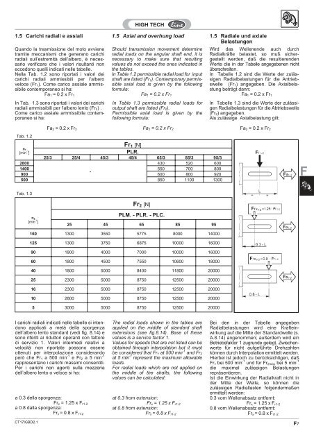
1.5 Carichi radiali e assiali 1.5 Axial and overhung load 1.5 Radiale und axiale<br />
Belastungen<br />
Quando la trasmissione del moto avviene<br />
tramite meccanismi che generano carichi<br />
radiali sull’estremità dell’albero, è necessario<br />
verificare che i valori risultanti non<br />
eccedono quelli indicati nelle tabelle.<br />
Nella Tab. 1.2 sono riportati i valori dei<br />
carichi radiali ammissibili per l’albero<br />
veloce (Fr1). Come carico assiale ammissibile<br />
contemporaneo si ha:<br />
Fa1 = 0.2 x Fr1<br />
In Tab. 1.3 sono riportati i valori dei carichi<br />
radiali ammissibili per l’albero lento (Fr2) .<br />
Come carico assiale ammissibile contemporaneo<br />
si ha:<br />
Tab. 1.2<br />
n1<br />
[min -1 ]<br />
Tab. 1.3<br />
Fa2 = 0.2 x Fr2<br />
I carichi radiali indicati nelle tabelle si intendono<br />
applicati a metà della sporgenza<br />
dell’albero lento standard (vedi fig. 8.14) e<br />
sono riferiti ai riduttori operanti con fattore<br />
di servizio 1. Valori intermedi relativi a<br />
velocità non riportate possono essere<br />
ottenuti per interpolazione considerando<br />
però che Fr1 a 500 min -1 eFr2 a 5 min -1<br />
rappresentano i carichi massimi consentiti.<br />
Per i carichi non agenti sulla mezzeria<br />
dell’albero lento o veloce si ha:<br />
a 0.3 della sporgenza:<br />
Frx =1.25xFr1-2<br />
a 0.8 dalla sporgenza:<br />
Frx = 0.8 x Fr1-2<br />
Should transmission movement determine<br />
radial loads on the angular shaft end, it is<br />
necessary to make sure that resulting<br />
values do not exceed the ones indicated in<br />
the tables.<br />
In Table 1.2 permissible radial load for input<br />
shaft are listed (Fr1). Contemporary permissible<br />
axial load is given by the following<br />
formula:<br />
Fa1 =0.2xFr1<br />
In Table 1.3 permissible radial loads for<br />
output shaft are listed (Fr2).<br />
Permissible axial load is given by the<br />
following formula:<br />
Fr1 [N]<br />
<strong>PLR</strong>.<br />
Fa2 =0.2xFr2<br />
25/3 25/4 45/3 45/4 65/3 85/3 95/3<br />
2800<br />
430 520 600<br />
1400<br />
900<br />
-<br />
550<br />
600<br />
700<br />
800<br />
800<br />
920<br />
500 850 1100 1300<br />
n2<br />
[min -1 ]<br />
Fr2 [N]<br />
<strong>PLM</strong>. - <strong>PLR</strong>. - <strong>PLC</strong>.<br />
25 45 65 85 95<br />
160 1300 3550 5775 8000 14000<br />
125 1300 3750 6875 10000 16000<br />
90 1800 4000 7000 10000 16000<br />
60 1800 4500 7550 10600 18000<br />
40 1800 5000 8400 11800 20000<br />
25 2300 5000 8750 12500 20000<br />
16 2300 5000 8750 12500 20000<br />
10 2800 5000 8750 12500 20000<br />
5 3000 5000 8750 12500 20000<br />
The radial loads shown in the tables are<br />
applied on the middle of standard shaft<br />
extensions (see fig.8.14). Base of these<br />
values is a service factor 1.<br />
Values for speeds that are not listed can be<br />
obtained through interpolation but it must<br />
be considered that Fr1 at 500 min -1 and Fr2<br />
at 5 min -1 represent the maximum allowable<br />
loads.<br />
For radial loads which are not applied on<br />
the middle of the shafts, the following<br />
values can be calculated:<br />
at 0.3 from extension:<br />
Frx = 1.25 x Fr1-2<br />
at 0.8 from extension:<br />
Frx = 0.8 x Fr1-2<br />
Wird das Wellenende auch durch<br />
Radialkräfte belastet, so muß sichergestellt<br />
werden, daß die resultierenden<br />
Werte die in der Tabelle angegebenen nicht<br />
überschreiten.<br />
In Tabelle 1.2 sind die Werte der zulässigen<br />
Radialbelastungen für die Antriebswelle<br />
(Fr1) angegeben. Die Axialbelastung<br />
beträgt dann:<br />
Fa1 =0.2xFr1<br />
In Tabelle 1.3 sind die Werte der zulässigen<br />
Radialbelastungen für die Abtriebswelle<br />
(Fr2) angegeben.<br />
Als zulässige Axialbelastung gilt:<br />
Fa2 =0.2xFr2<br />
Bei den in der Tabelle angegeben<br />
Radialbelastungen wird eine Krafteinwirkung<br />
auf die Mitte der Standardwelle (s.<br />
A.8.14) angenommen; außerdem wird ein<br />
Betriebsfaktor 1 zugrunde gelegt. Zwischenwerte<br />
für nicht aufgeführte Drehzahlen<br />
können durch Interpolation ermittelt werden.<br />
Hierbei ist jedoch zu berücksichtigen, daß<br />
Fr1 bei 500 min -1 und für Fr2max bei 5 min -1<br />
die maximal zulässigen Belastungen<br />
repräsentieren.<br />
Ist die Einwirkung der Radialkraft nicht in<br />
der Mitte der Welle, so können die<br />
zulässigen Radiallasten folgendermaßen<br />
ermittelt werden:<br />
0.3 vom Wellenabsatz entfernt:<br />
Frx = 1.25 x Fr1-2<br />
0.8 vom Wellenabsatz entfernt:<br />
Frx = 0.8 x Fr1-2<br />
CT17IGBD2.1 F7<br />
F