PLM PLR PLC
PLM PLR PLC
PLM PLR PLC

You also want an ePaper? Increase the reach of your titles
YUMPU automatically turns print PDFs into web optimized ePapers that Google loves.
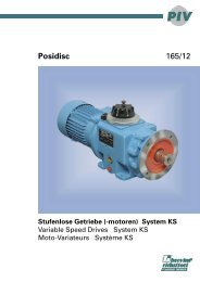
Nella tab. 1.4 sono riportate le grandezze motore<br />
accoppiabili (IEC) unitamente alle dimensioni<br />
albero/flangia motore standard.<br />
<strong>PLR</strong> 25/3<br />
<strong>PLR</strong>25/4<br />
<strong>PLR</strong> 45/3<br />
<strong>PLR</strong> 45/4<br />
<strong>PLR</strong> 65<br />
<strong>PLR</strong> 85<br />
<strong>PLR</strong> 95<br />
F12<br />
IEC<br />
112 (1)<br />
100 (1)<br />
In table 1.4 the possible shaft/flange dimensions<br />
IEC standard are listed.<br />
ir<br />
Tutti / All / Alle<br />
80 19/200 (B5) - 19/120 (B14) 19/160 - 19/140 - 19/105 � - 19/90 �<br />
71 14/160 (B5) - 14/105 (B14) 14/140 - 14/120 - 14/90�<br />
63 11/140 (B5) - 11/90� (B14) 11/160 - 11/120 - 11/105<br />
63 11/140 (B5) - 11/90 (B14) 11/120 - 11/80�<br />
56 9/120 (B5) - 9/80� (B14) 9/140 - 9/90<br />
28/250 (B5) - 28/160 (B14) 28/140<br />
28/250 (B5) - 28/160 (B14) 28/140<br />
90 24/200 (B5) - 24/140 (B14) - 24/250 - 24/160 - 24/120<br />
80 19/200 (B5) - 19/120 (B14) - 19/160 - 19/140 - 19/105�<br />
71 14/160 (B5) - 14/105� (B14) - 14/200 - 14/140 - 14/120<br />
80 19/200 (B5)<br />
71 14/160 (B5)<br />
112 28/250� (B5) - 28/160� (B14)<br />
100 28/250� (B5) - 28/160� (B14)<br />
90 24/200� (B5) - 24/140� (B14) 24/160� - 24/120�<br />
80 19/200� (B5) - 19/120� (B14) 19/160� - 19/140�<br />
71 14/160� (B5) 14/200� - 14/140� - 14/120�<br />
63 11/140� (B5)<br />
132 38/300� (B5) - 38/200� (B14) 38/250�<br />
112 28/250� (B5) - 28/160� (B14) 28/200� - 28/300�<br />
100 28/250� (B5) - 28/160� (B14) 28/200� - 28/300�<br />
90 24/200� (B5) - 24/140� (B14) 24/300� - 24/250� - 24/160� - 24/120�<br />
80 19/200� (B5) - 19/120� (B14) 19/160� - 19/140�<br />
71 14/160� (B5)<br />
160 42/350� (B5) - 42/300� - 42/250�<br />
132 38/300� (B5) - 38/350� - 38/250�<br />
112 28/250� (B5) - 28/350� - 28/300�<br />
100 28/250� (B5) - 28/350� - 28/300�<br />
90 24/200� (B5)<br />
80 19/200� (B5)<br />
In Tabelle 1.4 sind die möglichen Welle/Flansch-<br />
Abmessungen IEC-Standard aufgelistet.<br />
Tab. 1.4<br />
Possibili accoppiamenti con motori IEC - Possible couplings with IEC motors - Mögliche Verbindungen mit IEC-Motoren<br />
(1) ATTENZIONE!<br />
Linguette a disegno STM.<br />
(Vedere Paragrafo 1.11).<br />
Legenda:<br />
11/140 (B5) 11/120<br />
11/140 : combinazioni albero/flangia standard<br />
(B5) : forma costruttiva motore IEC<br />
11/120 : combinazioni albero/flangia a richiesta<br />
N.B.<br />
La configurazione standard della flangia attacco<br />
motore prevede 4 fori a 45° (esempio x:<br />
vedi par 2.3).<br />
Per le flange contrassegnate con il simbolo ( ) i<br />
fori per il fissaggio al motore sono disposti in<br />
croce (esempio +). Pertanto è opportuno<br />
valutare l’ingombro della morsettiera del motore<br />
che verrà installato in quanto essa verrà a<br />
trovarsi orientata a 45° rispetto agli assi. Per la<br />
scelta della posizione della morsettiera rispetto<br />
agli assi fare riferimento allo schema seguente<br />
(in cui la posizione 5 è quella standard):<br />
(1) WARNING!<br />
Key:<br />
11/140 (B5) 11/120<br />
11/140 : standard shaft/flange combination<br />
(B5) : IEC motor constructive shape<br />
11/120 : shaft/flange combinations upon request<br />
Note.<br />
The standard configuration for the 4 holes is<br />
45° to the axles (like an x: see par 2.3).<br />
For the B14 flanges marked with ( ) the holes to<br />
fit the motor are on the axles (like a +). Therefore<br />
we suggest to check the dimensions of the<br />
terminal board of the motor as it will be at 45° to<br />
the axles. Please choose the terminal board<br />
position refering to the following sketch (in which<br />
n° 5 is the standard position):<br />
(1) ACHTUNG!<br />
(Look at chapter 1.11). (s. S. 1.11).<br />
Legende:<br />
11/140 (B5) 11/120<br />
11/140 : Standardkombinationen Welle/Flansch<br />
(B5) : Konstruktionsform IEC-Motor<br />
11/120 : Sonderkombinationen Welle/Flansch<br />
HINWEIS.<br />
In der Standardkonfiguration sind die 4<br />
Flansch- bohrungen im 45°-Winkel zu den<br />
Achsen angeordnet (wie ein x: siehe kapitel<br />
2.3).<br />
Bei B14-Flanschen, die mit ( ) gekennzeichnet<br />
sind, sind die Bohrungen auf den Achsen<br />
angeord- net (wie ein +). Es sollte deshalb der<br />
Platzbedarf des Motorklemmenkastens<br />
beachtet werden, da er sich in 45°-Position zu<br />
den Achsen befinden wird. Die Lage des<br />
Klemmenkastens des Motors wählen Sie bitte<br />
anhand der folgenden Skizze (Pos. 5 ist<br />
Standardposition):<br />
CT17IGBD2.1