ventilconvettori canalizzati ductable fan coils ventilo-convecteurs ...
ventilconvettori canalizzati ductable fan coils ventilo-convecteurs ...
ventilconvettori canalizzati ductable fan coils ventilo-convecteurs ...

You also want an ePaper? Increase the reach of your titles
YUMPU automatically turns print PDFs into web optimized ePapers that Google loves.
VENTILCONVETTORI CANALIZZATI<br />
DUCTABLE FAN COILS<br />
VENTILO-CONVECTEURS CANALISÉS<br />
KANALISIERTE GEBLÄSEKONVEKTOREN<br />
UNIDADES FAN COILS CANALIZADAS<br />
LFC<br />
ISO 9001 - Cert. nº 0128/3<br />
AERMEC S.P.A.<br />
C E R T I F I E D<br />
Q U A L I T Y S Y S T E M<br />
MANUALE D’USO E INSTALLAZIONE<br />
USE AND INSTALLATION MANUAL<br />
MANUEL D'UTILISATION ET D'INSTALLATION<br />
BEDIENUNGS- UND INSTALLATIONSANLEITUNG<br />
MANUAL DE INSTRUCCIONES E INSTALACIÓN<br />
Sostituisce - Replace<br />
Remplace - Ersetzt:<br />
4025600_02/0401<br />
ILFCLJ<br />
0512<br />
4025600_03
I<br />
GB<br />
F<br />
D<br />
E<br />
INDICE CONTENTS INDEX INHALTSVERZEICHN ÍNDICE<br />
INFORMAZIONI GENERALI • GENERAL INFORMATION<br />
INFORMATIONS GENERALES ALLGEMEINE INFORMATIONEN INFORMACION GENERAL 4<br />
MISURE DI SICUREZZA SAFETY MEASURES MISURES DE SECURITE<br />
SICHEREITSMAßNAHMEN<br />
Trasporto • Carriage Transport Transport • Transporte<br />
Simboli di sicurezza Safety symbol Simboles de securite Sicherheitssymbole símbolos de seguridad 5<br />
CARATTERISTICHE FEATURES CARACTERISTIQUES EIGENSCHAFTEN CARACTERISTICAS<br />
Descrizione dell’unità Componenti principali 6<br />
Personalizzazioni 7<br />
Imballo Installazione dell’unità Collegamenti elettrici Rotazione batteria 8<br />
Description of the unit main description 9<br />
Customisations 10<br />
Packing Unit installation Electrical connections Rotating the coil 11<br />
Description de l’unité Principaux composants 12<br />
Personnalisations 13<br />
Emballage Installation de l’unité Raccordements electriques Rotation de la batterie 14<br />
Beschreibung der einheit Hauptkomponenten 15<br />
Anpassung 16<br />
Verpackung Installation des Gerätes Elektrische anschlüsse Idrehen der batterie 17<br />
Descripción de la unidad Componentes principales 18<br />
Personalizacion 19<br />
Embalaje Installación de la unidad Conexiones eléctricas Rotación de la batería 20<br />
DATI DIMENSIONALI DIMENSIONS DIMENSIONS ABMESSUNGEN DIMENSIONES 21<br />
SCHEMI ELETTRICI WIRING DIAGRAMS SCHEMAS ELECTRIQUES<br />
SCHALTPLANE ESQUEMAS ELECTRICOS 29<br />
MANUTENZIONE MANITENANCE ENTRETIEN WARTUNG MANTENIMIENTO 33<br />
3
AERMEC S.p.A.<br />
I-37040 Bevilacqua (VR) Italia – Via Roma, 44<br />
Tel. (+39) 0442 633111<br />
Telefax (+39) 0442 93730 – (+39) 0442 93566<br />
www.aermec.com - info@aermec.com<br />
Bevilacqua, 01/01/2005 La Direzione Commerciale - Sales and Marketing Director<br />
LUIGI ZUCCHI<br />
4<br />
LFC<br />
DICHIARAZIONE DI CONFORMITÀ<br />
Noi, firmatari della presente, dichiariamo sotto la nostra esclusiva responsabilità, che la macchina in oggetto è conforme a quanto prescritto<br />
dalle seguenti Direttive:<br />
- Direttiva macchine 89/392 CEE e modifiche 91/368 CEE - 93/44 CEE - 93/68 CEE;<br />
- Direttiva bassa tensione 73/23 CEE;<br />
- Direttiva compatibilità elettromagnetica EMC 89/36 CEE.<br />
LFC CON ACCESSORI<br />
è fatto divieto di mettere in servizio il prodotto dotato di accessori non di fornitura Aermec prima che gli stessi siano dichiarati conformi<br />
alle disposizioni della direttiva sopraccitata.<br />
DECLARATION OF CONFORMITY<br />
We declare under our own responsability that the above equipment complies with provisions of the following Standards:<br />
- Equipment Standard 89/392 CEE and amandments 91/368 CEE - 93/44 EEC - 93/68 EEC;<br />
- Low voltage Standard 73/23 EEC;<br />
- Electromagnetic compatibility Standard EMC 89/36 EEC.<br />
LFC WITH ACCESSORIES<br />
It is not allowed to use the unit equipped with accessories not supplied by Aermec, before they are declared to comply with the provisions<br />
of above regulations.<br />
CERTIFICAT DE CONFORMITE<br />
Nous, signataires de la présente, certifions sous notre propre responsabilité, que l’appareil en objet est conforme aux suivantes Directives:<br />
- Directive appareil 89/392 EEC e modifications 91/368 EEC - 93/44 EEC - 93/68 EEC;<br />
- Directive basse tension 73/23 EEC;<br />
- Direttiva compatibilità elettromagnetica EMC 89/36 EEC.<br />
LFC PLUS ACCESSOIRES<br />
Il est interdit de faire fonctionner l'appareil avec des accessoires qui ne sont pas fournis de Aermec, avant que les memes accessoires ne<br />
seront pas certifiés conformes aux dispositions de la directive.<br />
KONFORMITÄTSERKLÄRUNG<br />
Wir, Unterzeichner dieser Bescheinigung, bestätigen, daß diese Geräte den Vorschriften:<br />
- Vorschrift Geräte 89/392 EWG und entersprechende ergänzungen 91/368 EWG - 93/44 EWG - 93/68 EWG;<br />
- Niederspannung - Vorschrift 73/23 EWG;<br />
- Funkentstörung - Vorschrift EMC 89/36 EWG.<br />
LFC + ZUBEHÖR<br />
Falls das Gerät mit Zubehörteilen ausgerüstet wird, die nicht von Aermec geliefert werden, ist dessen Inbetriebnahme solange untersagt,<br />
bis die Komformität dieser Zubehörteile mit den Bestimmungen der unten angeführten Richtlinien festgestellt ist.<br />
DECLARACION DE CONFORMIDAD<br />
Declaramos bajo nuestra responsabilidad que los equipos arriba indicados cumplen con las siguientes directivas:<br />
- Máquinas 89/392 CEE y modificaciones 91/368 CEE, 93/44 CEE y 93/68 CEE;<br />
- Baja tensión 73/23 CEE;<br />
- Compatibilidad electromagnética (CEM) 89/36 CEE.<br />
LFC CON ACCESORIOS<br />
Está prohibido poner en marcha el producto con accesorios no suministrados por Aermec antes de que los mismos hayan sido declarados<br />
conformes con las disposiciones de la directiva arriba citada.<br />
Aermec partecipa al Programma di Certificazione EUROVENT. I prodotti interessati figurano nella Guida EUROVENT dei Prodotti Certificati.<br />
Aermec is partecipating in the EUROVENT Certification Programme. Products are as listed in the EUROVENT Directory of Certified Products.<br />
Aermec partecipe au Programme de Certification EUROVENT. Les produits figurent dans l’Annuaire EUROVENT des Produits Certifiés.<br />
Aermec ist am Zertifikations - Programm EUROVENT beteiligt. Die entsprechend gekennzeichneten Produkte sind im EUROVENT - Jahrbuch aufgefürt.<br />
AERMEC S.p.A. participa en el programa de certificación EUROVENT. Sus equipos aparecen en el directorio de productos certificados EUROVENT.
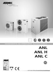
TRASPORTO CARRIAGE TRANSPORT TRANSPORT TRANSPORTE<br />
NON bagnare Do NOT wet<br />
CRAINT l’humidité Vor Nässe schützen<br />
NO mojar<br />
Sovrapponibilità: controllare sull’imballo la posizione della freccia per<br />
conoscere il numero di macchine impilabili.<br />
Stacking: control the packing for the arrow position to know the number<br />
of machines that can be stacked.<br />
Empilement: vérifier sur l’emballage la position de la flèche pour connaître<br />
le nombre d’appareils pouvant être empilés.<br />
Stapelung: Anhand der Position des Pfeiles an der Verpackung kontrollieren,<br />
wieviele Geräte stapelbar sind.<br />
Apilamiento: observe en el embalaje la posición de la flecha para saber<br />
cuántos equipos pueden apilarse.<br />
NON trasportare la macchina da soli se il suo peso supera i 35 Kg.<br />
DO NOT handle the machine alone if its weight is over 35 Kg.<br />
NE PAS transporter tout seul l’appareil si son poids dépasse 35 Kg.<br />
Das Gerät NICHT alleine tragen, wenn sein Gewicht 35 Kg überschreitet.<br />
NO maneje los equipos en solitario si pesan más de 35 kg.<br />
SIMBOLI DI SICUREZZA SAFETY SYMBOL SIMBOLES DE SECURITE<br />
SICHERHEITSSYMBOLE SIMBOLOS DE SEGURIDAD<br />
NON calpestare Do NOT trample<br />
NE PAS marcher sur cet emballage Nicht betreten<br />
NO pisar<br />
6<br />
5<br />
4<br />
3<br />
2<br />
1<br />
NON lasciare gli imballi sciolti durante il trasporto.<br />
Do NOT leave loose packages during transport.<br />
ATTACHER les emballages pendant le transport.<br />
Die Verpackungen nicht ungesichert transportieren.<br />
NO lleve las cajas sueltas durante el transporte.<br />
35 Kg<br />
Pericolo: Pericolo: Pericolo!!!<br />
Tensione Organi in movimento<br />
Danger: Danger: Danger!!!<br />
Power supply Movings parts<br />
Danger: Danger: Danger!!!<br />
Tension Organes en mouvement<br />
Gefahr ! Gefahr ! Gefahr!!!<br />
Spannung Rotierende Teile<br />
Peligro: Peligro: Peligro!!!<br />
Tensión Elementos en movimiento<br />
5
I<br />
DESCRIZIONE DELL’UNITÀ<br />
SCOPO DELLA MACCHINA<br />
Il ventilconvettore LFC è un terminale per il trattamento<br />
dell’aria sia nella stagione invernale sia in quella estiva.<br />
Il ventilconvettore LFC è stato concepito per essere inserito<br />
in impianti <strong>canalizzati</strong>, personabilizzabile su qualsiasi<br />
impianto grazie all’ampia gamma di accessori.<br />
VERSIONI E GRANDEZZE DISPONIBILI<br />
I <strong>ventilconvettori</strong> della serie LFC sono disponibili in:<br />
2 grandezze con batteria a 4 ranghi<br />
LFC1240 LFC1440<br />
2 grandezze con batteria a 4 ranghi + 1 rango<br />
LFC1241 LFC1441<br />
2 grandezze con batteria a 4 ranghi con allogiamento per<br />
resistenza elettrica a candela (non fornita)<br />
LFC1241R LFC1441R<br />
2 grandezze con batteria a 5 ranghi<br />
LFC1250 LFC1450<br />
CARATTERISTICHE TECNICHE:<br />
Terminale per il trattamento dell’aria per installazione orizzontale,<br />
costituito da un gruppo ventilante e da una batteria per raffreddamento<br />
e o riscaldamento, per impianti a due o a quattro tubi oltre<br />
alla possibilità di abbinare resistenze elettriche per il riscaldamento.<br />
LFC è stato concepito per consentire un facile accesso alla componentistica<br />
e di conseguenza l’installazione e la manutenzione<br />
saranno agevolate. LFC è personalizzabile con una vasta gamma di<br />
accessori per adattarsi alle più diverse esigenze di impianto, sono<br />
disponibili flange e plenum per collegare il terminale a canalizzazioni<br />
sia in aspirazione che in mandata, dritte e curve. Il ventilconvettore<br />
LFC può essere abbinato a pannelli comandi con commutatore di velocità<br />
o termostato elettronico (accessori). Per collegare un termostato<br />
elettronico ai <strong>ventilconvettori</strong> LFC è necessario l’utilizzo di una scheda<br />
di interfaccia SIT. E' possibile utilizzare uno stesso pannello comandi<br />
per più <strong>fan</strong>coil a patto di mettere una scheda di interfaccia per ogni <strong>fan</strong>coil.<br />
E’ possibile avere differenti prevalenze residue per le eventuali<br />
canalizzazioni grazie al motore ventilatore a 5 velocità; con i pannelli<br />
comandi a 3 velocità è possibile selezionare le tre preferite (collegamenti<br />
disponibili sulla morsettiera). Batterie reversibili con alette corrugate<br />
a 4 e a 5 ranghi (impianti a due tubi) e a 4 ranghi +1 (impianti a<br />
quattro tubi), con possibilità di batteria aggiuntiva e resistenza elettrica<br />
oltre ad una ampia gamma di altri accessori.<br />
Il libero accesso all’unità base deve essere impedito mediante l’utilizzo<br />
di opportuni mezzi, quali reti o griglie di protezione, conformi<br />
alla UNI EN 294.<br />
PERSONALIZZAZIONI (ACCESSORI):<br />
ACCESSORI OBBLIGATORI:<br />
I terminali LFC in alcune tipologie di installazione devono obbligatoriamente<br />
essere abbinati a degli accessori dedicati.<br />
BCL 10 - Bacinella integrale in poliuretano espanso per la raccolta<br />
della condensa, ispezionabile dal basso copre sia la batteria che gli<br />
attacchi idraulici.<br />
Accessorio obbligatorio nel funzionamento a freddo e in abbinamento<br />
con le valvole VCL.<br />
CA - COFANO DI ASPIRAZIONE<br />
Il co<strong>fan</strong>o di aspirazione permette di racchiudere il gruppo di ventilazione<br />
in un co<strong>fan</strong>o, è realizzato in lamiera zincata. E' dotato di<br />
staffe per il fissaggio a soffitto.<br />
Accessorio obbligatorio in abbinamento alla flangia di aspirazione<br />
FA1200<br />
CA4 - COFANO DI ASPIRAZIONE CON FILTRO AD ALTA EFFICIENZA<br />
Il co<strong>fan</strong>o di aspirazione permette di racchiudere il gruppo di ventilazione<br />
in un co<strong>fan</strong>o, è realizzato in lamiera zincata. E' dotato di<br />
staffe per il fissaggio a soffitto.<br />
Il filtro è in classe G4 secondo EN779.<br />
Accessorio obbligatorio in abbinamento alla flangia di aspirazione<br />
FA1200<br />
SIT - Scheda interfaccia per collegare i pannelli comandi elettronici<br />
ai <strong>ventilconvettori</strong> LFC, si applica nella scatola elettrica del ventilconvettore.<br />
E' possibile utilizzare uno stesso pannello comandi per<br />
più <strong>fan</strong>coil a patto di mettere una scheda di interfaccia per ogni<br />
<strong>fan</strong>coil.<br />
Accessorio obbligatorio in abbinamento ai termostati elettronici.<br />
6<br />
ACCESSORI:<br />
FA1200 - FLANGIA DI ASPIRAZIONE CON RACCORDI<br />
La flangia di aspirazione è dotata di raccordi a sezione circolare di<br />
diametro 225 mm, è realizzata in lamiera zincata.<br />
Accessorio da abbinare al co<strong>fan</strong>o di aspirazione CA / CA4.<br />
PA1200 - PLENUM DI ASPIRAZIONE REVERSIBILE<br />
Plenum di aspirazione reversibile (aspirazione longitudinale ed<br />
ortogonale) con raccordi a sezione circolare di diametro 225 mm, è<br />
realizzato in lamiera zincata.<br />
PM1200 - PLENUM DI MANDATA REVERSIBILE<br />
Plenum di mandata reversibile (mandata longitudinale ed ortogonale)<br />
con raccordi a sezione circolare di diametro 225 mm, è realizzato in<br />
lamiera zincata e coibentato internamente.<br />
PX2 PANNELLO COMANDI<br />
Pannello comandi da installarsi a parete, costituito da commutatore<br />
acceso/spento e da commutatore a tre posizioni per la selezione<br />
della velocità del ventilatore.<br />
PXB PANNELLO COMANDI ELETTRONICO<br />
Pannello comandi da installarsi a parete con termostato ambiente<br />
di tipo elettronico per il controllo dell’accensione e dello spegnimento<br />
del ventilatore. Il pannello comandi è dotato di un commutatore<br />
acceso/spento, di un commutatore estate/inverno, di un commutatore<br />
per la selezione della velocità del ventilatore e di una manopola<br />
per la regolazione della temperatura ambiente.<br />
La sonda di temperatura ambiente é posizionata all’interno del termostato.<br />
Non é possibile l’accoppiamento del termostato con una sonda<br />
della temperatura dell’acqua.<br />
Per ulteriori informazioni si rimanda alle istruzioni dell’accessorio.<br />
PXL2E PANNELLO COMANDI ELETTRONICO MULTIFUNZIONE<br />
Pannello comandi dotato di termostato elettronico multifunzione<br />
per impianti a 2 tubi, installazione a parete.<br />
Controlla il funzionamento del ventilconvettore in funzione della<br />
modalità impostata, della temperatura ambiente e della temperatura<br />
dell’acqua nel circuito per mantenere nell’ambiente la temperatura<br />
impostata.<br />
Il pannello comandi va utilizzato su impianti a 2 tubi con la possibilità<br />
di collegare una valvola (accessorio VCL) di tipo On - Off per<br />
l'intercettazione dell'acqua di alimentazione della batteria.<br />
La sonda di temperatura ambiente é posizionata all’interno del termostato.<br />
Il pannello può essere collegato ad una sonda SW3 (accessorio) di<br />
rilevazione della temperatura dell’acqua nella batteria di riscaldamento.<br />
Per ulteriori informazioni si rimanda alle istruzioni dell’accessorio.<br />
PXL4 PANNELLO COMANDI ELETTRONICO MULTIFUNZIO-<br />
NE<br />
Pannello comandi dotato di termostato elettronico multifunzione<br />
per impianti a 4 tubi o a 2 tubi, installazione a parete. Controlla il<br />
funzionamento del ventilconvettore in funzione della modalità<br />
impostata, della temperatura ambiente e della temperatura<br />
dell’acqua nel circuito per mantenere nell’ambiente la temperatura<br />
impostata.<br />
Il pannello comandi va utilizzato su impianti a 4 tubi o a 2 tubi più<br />
resistenza, con la possibilità di collegare due valvole (accessori VCL) di<br />
tipo On - Off per l'intercettazione dell'acqua di alimentazione delle<br />
batterie oppure una valvola (accessorio VCL) e una resistenza elettrica<br />
(accessori RX), ha quindi le funzioni per la gestione di una una resistenza<br />
elettrica RX (in integrazione o in sostituzione). La resistenza elettrica<br />
può essere abilitata manualmente agendo su di un pulsante del pannello<br />
comandi.<br />
Il termostato è dotato di una sonda di temperatura ambiente al suo<br />
interno.<br />
Il Change Over automatico lato aria, consente di stabilire automaticamente<br />
il modo di funzionamento del terminale a Caldo o a<br />
Freddo a seconda della differenza tra la temperatura impostata e la<br />
temperatura rilevata nell’ambiente.<br />
Per ulteriori informazioni si rimanda alle istruzioni dell’accessorio.<br />
RX 1200 - Resistenza elettrica di tipo corazzato da 3000 W con<br />
alettatura in acciaio, installabile in tutte le configurazioni (4 ranghi,<br />
5 ranghi, 4+1 ranghi). E' dotata di doppio termostato, il primo a<br />
riarmo automatico ed il secondo a riarmo manuale.<br />
SW3 SONDA DI MINIMA TEMPERATURA ACQUA<br />
L’accessorio SW3 è una sonda di rilevazione della temperatura<br />
dell’acqua nella batteria di riscaldamento, per impedire il funzionamento<br />
dei ventilatori quando la temperatura dell’acqua è minore di<br />
39 °C. Le sonde SW3 sono predisposte per alimentazione a 230V<br />
monofase.<br />
VCL 1 - Valvola a tre vie, quattro attacchi, per la batteria principale<br />
a 4 o 5 ranghi.<br />
VCL 2 - Valvola a tre vie, quattro attacchi, per la batteria di riscaldamento<br />
a 1 rango.
IMBALLO<br />
I <strong>ventilconvettori</strong> vengono spediti con imballo standard<br />
costituito da protezioni di polistirolo espanso e cartone.<br />
INSTALLAZIONE DELL’UNITÀ<br />
Il libero accesso all’unità base deve essere impedito<br />
mediante l’utilizzo di opportuni mezzi, quali reti o griglie<br />
di protezione, conformi alla UNI EN 294.<br />
Il ventilconvettore deve essere installato in posizione tale da<br />
consentire facilmente la manutenzione ordinaria (pulizia<br />
del filtro) e straordinaria, nonchè l’accesso alle valvole di<br />
sfiato dell’aria e di svuotamento dell’unità sui tubi di ingresso<br />
ed uscita dell’acqua nella batteria di scambio.<br />
Il luogo di montaggio deve essere scelto in modo che il<br />
limite di temperatura ambiente massimo e minimo venga<br />
rispettato 0÷45°C (
GB<br />
DESCRIPTION OF THE UNIT<br />
PURPOSE OF THE MACHINE<br />
The LFC <strong>fan</strong> coil unit is a terminal for the treatment of air in<br />
winter and in summer.<br />
The LFC <strong>fan</strong> coil unit has been designed to be incorporated<br />
into channelled systems and can be tailored to suit any<br />
system thanks to its wide range of accessories.<br />
AVAILABLE VERSIONS AND SIZES<br />
<strong>fan</strong> coil units in the LFC series are available in:<br />
2 sizes with 4-row battery<br />
LFC1240 LFC1440<br />
2 sizes with 4- + 1 row battery<br />
LFC1241 LFC1441<br />
2 sizes with 4-row battery with housing for candle-type<br />
electric resistor (not supplied)<br />
LFC1241R LFC1441R<br />
2 sizes with 5-row battery<br />
LFC1250 LFC1450<br />
TECHNICAL CHARACTERISTICS:<br />
Terminal for air treatment for horizontal installation consisting of a<br />
<strong>fan</strong> unit and a battery for cooling or heating, for systems with two or<br />
four pipes as well as the possibility of combining electrical resistors<br />
for heating.<br />
LFC has been designed to give easy access to the components and<br />
consequently the installation and maintenance will be made simplier.<br />
LFC can be tailored with a wide range of accessories to suit the<br />
most disparate system requirements, flanges and plenum chambers<br />
are available to connect the terminal to intake and deliver channels<br />
whether straight or "crooked”.<br />
LFC <strong>fan</strong> coil units can be combined with control panels with speed<br />
connectors or electronic thermostats (accessories). To connect an<br />
electronic thermostat to the LFC <strong>fan</strong> coil units a SIT interface card<br />
must be used.<br />
A single control panel can be used for several <strong>fan</strong> <strong>coils</strong> providing an<br />
interface card is installed for each <strong>fan</strong> coil.<br />
It is possible to have different residual heads for any channelling<br />
thanks to the five-speed <strong>fan</strong> motor; with control panels with threespeed<br />
selector it is possible to select the three most frequently used<br />
(connections available on the terminal block).<br />
Reversible four/ and five-row batteries with corrugated fins (twopipe<br />
version) and four + 1 row (systems with four pipes), with possibility<br />
of additional batteries and electrical resistors in addition to a<br />
wide range of other accessories.<br />
The free access to the base unit must be prevented by means of<br />
suitable devices such as protection meshes or grilles, in conformity<br />
with UNI EN 294.<br />
CUSTOMISATIONS (ACCESSORIES):<br />
OBLIGATORY ACCESSORIES:<br />
The LFC terminals in some types of installation may be compulsorily<br />
linked to dedicated accessories.<br />
BCL 10 - Integral foam polyurethane drip pan for the collection of<br />
condensate, that can be inspected from underneath, covers both<br />
the battery and the plumbing connections.<br />
Obligatory accessory for cold operation and in conjunction with<br />
the VCL valves.<br />
CA - INTAKE CASING<br />
The intake casing makes it possible to close of the ventilation<br />
assembly in a casing. It is made of galvanised sheet steel. It has<br />
brackets for ceiling mounting.<br />
An obligator accessory in combination with the FA1200 intake<br />
flange<br />
CA4 - INTAKE CASING WITH HIGH-EFFICIENCY FILTER<br />
The intake casing makes it possible to close of the ventilation<br />
assembly in a casing. It is made of galvanised sheet steel. It has<br />
brackets for ceiling mounting.<br />
G4 class filter in accordance with standard EN779.<br />
An obligator accessory in combination with the FA1200 intake<br />
flange<br />
SIT - Interface card for connecting the electronic control panels to<br />
the LFC <strong>fan</strong> <strong>coils</strong> is applied in the electrical <strong>fan</strong> coil box. A single<br />
control panel can be used for several <strong>fan</strong> <strong>coils</strong> providing an interfa-<br />
8<br />
ce card is installed for each <strong>fan</strong> coil.<br />
Obligatory accessory in conjunction with the electronic thermostats.<br />
ACCESSORIES:<br />
FA1200 - INTAKE FLANGE WITH FITTINGS<br />
The intake flange is fitted with circular cross section fittings 225 mm<br />
in diameter made of galvanised sheet steel.<br />
Accessory to be combined with CA / CA4.<br />
PA1200 - REVERSIBLE INTAKE PLENUM<br />
Reversible intake plenum (lengthwise and orthoganal intake) with<br />
circular section fittings 225 mm in diameter, made of galvanised<br />
sheet steel.<br />
PM1200 - REVERSIBLE DELIVERY PLENUM<br />
Reversible intake plenum (lengthwise and orthogonal intake) with<br />
circular section fittings 225 mm in diameter, made of galvanised<br />
sheet steel and insulated internally.<br />
PX2 CONTROL PANEL<br />
Control panel to be fitted on the wall, consisting of on/off selector<br />
switch and three-position selector switch to select <strong>fan</strong> speed.<br />
PXB ELECTRONIC CONTROL PANEL<br />
Control panel to be installed on the wall with electronic room thermostat<br />
for the control of the turning on and turning off of the <strong>fan</strong>. The<br />
control panel is fitted with an on/off selector switch, summer/winter<br />
selector switch, a selector switch for the selection of the <strong>fan</strong> speed<br />
and a knob for regulating the room temperature.<br />
The room temperature sensor is situated inside the thermostat.<br />
The thermostat can be coupled with a water temperature sensor.<br />
See the accessory instructions for further information.<br />
PXL2E ELECTRONIC MULTI-FUNCTION CONTROL PANEL<br />
Control panel fitted with electronic multifunction thermostat for<br />
wall-mounted two-pipe systems.<br />
Control of the <strong>fan</strong> coil function in accordance with the mode set,<br />
the room temperature and water temperature in the circuit to maintain<br />
the set temperature in the room.<br />
The control panel must bee used with two-pipe systems with the<br />
possibility of an on-off valve (accessory VCL) to cut off the water<br />
feeding the battery.<br />
The room temperature sensor is situated inside the thermostat.<br />
The panel can be linked to a SW3 detection sensor for the heat of<br />
the water inside the battery (accessory).<br />
See the accessory instructions for further information.<br />
PXL4 ELECTRONIC MULTIFUNCTION CONTROL PANEL<br />
Control panel fitted with electronic multifunction thermostat for<br />
wall-mounted four- or two-pipe systems.2 Control of the <strong>fan</strong> coil<br />
function in accordance with the mode set, the room temperature<br />
and water temperature in the circuit to maintain the set temperature<br />
in the room.<br />
The control panel must be used on four pipe systems or two-pipe<br />
systems with resistor, with the possibility of connecting two valves (VCL<br />
accessories) of the On - Off type for cutting off the water feeding the<br />
batteries or a valve (accessory VCL) and an electrical resistor (RX accessories),<br />
thus it has the functions for the management of an electrical<br />
resistor RX (in addition or as a substitution). The electrical resistor can<br />
be enabled manually by pressing a button on the control panel.<br />
The thermostat is fitted with a room temperature sensor inside it.<br />
The automatic air side Change Over makes it possible to automatically<br />
set the functioning mode of the Hot or Cold terminal according<br />
to the differences between the temperature set and the temperature<br />
detected in the room.<br />
See the accessory instructions for further information.<br />
RX 1200 - Armoured 3000 W electrical resistor with steel fins that<br />
can be installed in all the configurations (4 rows, 5 rows, 4+1<br />
rows). It is fitted with a double thermostat, the first to automatically<br />
rearm and the second to manually rearm.<br />
SW3 MINIMUM WATER TEMPERATURE SENSOR<br />
The SW3 accessory is a detector sensor for the temperature of the<br />
water inside the heating battery to prevent the <strong>fan</strong>s from working<br />
when the water temperature is less than 39 °C. The SW3 sensors are<br />
arranged for 230V single phase power supply.<br />
VCL 1 - Thee-way, four-connection valve or 4- or 5-row main battery.<br />
VCL 2 - Thee-way, four-connection valve for 1--row heating battery.
PACKING<br />
The <strong>fan</strong> <strong>coils</strong> are shipped in standard packaging and are<br />
protected by expanded polystyrene and cardboard.<br />
UNIT INSTALLATION<br />
Free access to the base unit must be avoided by using the<br />
appropriate means, which is netting or protective grilles,<br />
conforming to UNI EN 294.<br />
The <strong>fan</strong> coil must be installed in a position that will allow<br />
easy access for routine (cleaning of the filter) and extraordinary<br />
maintenance, as well as access to the air release<br />
valves and the input and output tubes for emptying the<br />
water in the exchange coil on the unit.<br />
The installation point must be chosen so that the minimum<br />
and maximum ambient temperatures of 0 - 45 °C are<br />
respected (< 85 % R.H.).<br />
Before performing any maintenance intervention protect<br />
yourself with the proper safety equipment.<br />
To install the unit proceed as follows:<br />
a) For ceiling mounting use the expansion bolts (not supplied)<br />
as indicated in Fig. 5.<br />
b)Perform the hydraulic connections. The position and the<br />
diameter of the hydraulic connections are reported with<br />
the dimensional data.<br />
It is recommended that the water piping be properly insulated<br />
to avoid dripping during the cooling operation.<br />
c) Apply the integral condensate drip tray BCL 10.<br />
The condensate discharge system must be correctly measured<br />
and the piping positioned in a way that will maintain<br />
an adequate inclination for the entire distance (min.<br />
1%). If draining into the sewer system, the implementation<br />
of a siphon is recommended which prohibits the<br />
return of unpleasant odors into the rooms.<br />
d)Perform the electrical connections according to that<br />
reported in the wiring diagrams and in the dedicated<br />
chapter. For access to the unit terminal strip remove the<br />
closing panel of the electrical box.<br />
e) Remount the closing panel of the electrical box.<br />
f) Apply the accessories.<br />
g) Connect the <strong>fan</strong> coil to the air intake and delivery ducts.<br />
ELECTRICAL CONNECTIONS<br />
Warning: before performing any maintenance intervention<br />
protect yourself with the proper safety equipment.<br />
Warning: before performing any maintenance intervention,<br />
make sure that the power supply is disconnected.<br />
WARNING: the electrical connections, the installation of<br />
the <strong>fan</strong> <strong>coils</strong> and their accessories must only be done by<br />
qualified individuals possessing the technical-professional<br />
requirements for the installation, trasformation, expansion<br />
and maintenance of the plants and able to verify the function<br />
and safety of these.<br />
In the specific case of electrical connections, the following<br />
must be checked:<br />
- Measurement of the isolation resistance of the electrical<br />
system.<br />
- Testing of the continuity of protection conductors.<br />
CONNECTION CABLE CHARACTERISTICS<br />
Use type H05V-K or N07V-K cables with 300/500 V insulation<br />
routed in either a tube or cable duct.<br />
All the cables must be routed in either a tube or cable duct<br />
so that they are not inside the <strong>fan</strong> coil.<br />
The cables exiting the tube or cable duct must be positioned<br />
in such a way as not to undergo traction or twisting stresses<br />
and at any rate protected from external agents.<br />
Stranded wires can only be used if fitted with end terminals.<br />
Make sure that all strands are securely inserted in the<br />
terminals.<br />
Stranded wires can only be used if fitted with end terminals.<br />
Make sure that all strands are securely inserted in the terminals.<br />
For all the connections follow the wiring diagrams accompanying<br />
the device and shown in this documentation.<br />
In order to protect the unit from short-circuits, mount an<br />
omnipolar thermal-magnetic switch 2A 250V (IG) to the<br />
power supply line with a minimum opening distance of 3 mm<br />
between the contacts.<br />
Each control panel can only control one <strong>fan</strong> coil.<br />
Never mount the control panel on a metal wall unless it is permanently<br />
grounded.<br />
The control panels are composed only of electric circuits connected<br />
to the 230V mains; all the probes and commands must<br />
therefore be insulated in correspondence to this voltage.<br />
By choosing the proper connections on the unit terminal strip,<br />
three selectable speeds of operation of the five available are<br />
enabled.<br />
The control panel with PX2 selector switch allows the <strong>fan</strong> coil<br />
to be connected either to the terminal strip of the panel or to<br />
the terminal strip of the unit.<br />
The panels equipped with electronic thermostats are all supplied<br />
with minimum water temperature probes, with the<br />
exception of the PXB.<br />
The minimum water temperature probe, to be positioned on<br />
the delivery tube, can automatically stop the <strong>fan</strong> if the input<br />
water temperature to the coil goes below 39°C.<br />
If the three-way valve is installed, the minimum water temperature<br />
probe must be placed on the delivery tube upstream<br />
from the valve.<br />
WARNING: THE PROBE IS DOUBLE INSULATED BECAU-<br />
SE IT IS SUBJECT TO A VOLTAGE OF 230V AC.<br />
For the control panels with PXL2E and PXL4 electronic thermostats,<br />
it is possible to connect an external contact to the<br />
internal terminal strip (EX), which would allow remote control<br />
of the <strong>fan</strong> coil.<br />
The multifunctional electronic thermostats are supplied<br />
ready to operate in the standard configuration, but allow the<br />
installer to adapt to the specific needs of the plant by adjusting<br />
the internal Dip-Switch.<br />
The personalized functions can vary from model to model,<br />
for this we recommend that you consult the relative<br />
manuals.<br />
Warning: check that the installation has been performed<br />
correctly. For PXL2E and PXL4 it is necessary to run the<br />
Autotest to check that the <strong>fan</strong> unit, the valves and the heater<br />
are all operating correctly.<br />
COIL ROTATION<br />
If, for reasons of hydraulic installation, the coil should be<br />
rotated. Proceed as follows:<br />
- remove the zinc plated sheet upper closure that is fastened<br />
with 4 screws.<br />
- remove the screws that fasten the coil (4 screws per side);<br />
- unthread the coil upwards;<br />
- rotate the coil;<br />
- reposition the coil in the unit;<br />
- fasten the coil with the screws;<br />
- remount the upper closure and fasten it with the screws,<br />
respecting<br />
9<br />
GB
F<br />
DESCRIPTION DE L'UNITE<br />
DESTINATION DE LA MACHINE<br />
Le <strong>ventilo</strong>-convecteur LFC est un terminal pour le traitement<br />
de l'air aussi bien en été qu'en hiver.<br />
Le <strong>ventilo</strong>-convecteur LFC a été réalisé pour être installé<br />
dans des installations canalisées, il peut s'adapter à toutes<br />
les installations grâce à sa vaste gamme d'accessoires.<br />
VERSIONS ET GRANDEURS DISPONIBLES<br />
Les <strong>ventilo</strong>-<strong>convecteurs</strong> LFC sont disponibles en:<br />
2 grandeurs avec batteries à 4 rangs<br />
LFC1240 LFC1440<br />
2 grandeurs avec batteries à 4 rangs+ 1 rang<br />
LFC1241 LFC1441<br />
2 grandeurs avec batteries à 4 rangs avec boîtier pour résistance<br />
électrique avec bougie (non fournie)<br />
LFC1241R LFC1441R<br />
2 grandeurs avec batteries à 5 rangs<br />
LFC1250 LFC1450<br />
CARACTÉRISTIQUES TECHNIQUES<br />
Terminal pour le traitement de l'air pour installation horizontale, composé<br />
d'un groupe de ventilation et d'une batterie pour le refroidissement<br />
et ou le chauffage, pour des installations à deux ou à quatre<br />
tubes avec également la possibilité d'ajouter des résistances électriques<br />
pour le chauffage.<br />
LFC a été réalisé de manière à ce qu'on puisse accéder facilement aux<br />
composants ce qui facilite l'installation et l'entretien.<br />
LFC peut être personnalisé car grâce à une vaste gamme d'accessoires,<br />
il s'adapte à toutes les exigences d'installation, on peut disposer<br />
de brides droites et "tordues" et de plenum pour relier le terminal à<br />
des canalisations aussi bien en aspiration qu'en refoulement.<br />
Le <strong>ventilo</strong>-convecteur LFC peut être associé à des panneaux de<br />
commande avec commutateur de vitesse ou thermostat électronique<br />
(accessoires). Pour connecter un thermostat électronique aux<br />
<strong>ventilo</strong>-<strong>convecteurs</strong> LCF il faut utiliser une carte d'interface SIT. On<br />
peut utiliser le même panneau de commandes pour plusieurs <strong>ventilo</strong>-<strong>convecteurs</strong><br />
à condition de mettre une carte d'interface pour<br />
chacun d'entre eux. On peut avoir plusieurs pression statiques résiduelles<br />
pour les éventuelles canalisations grâce au moteur ventilateur à 5 vitesses;<br />
Avec les panneaux de commande à 3 vitesses on peut sélectionner<br />
les trois préférées (connexions disponibles sur le bornier).<br />
Batteries réversibles avec ailettes cannelées à 4 et à 5 rangs (installations<br />
à deux tubes) et à 4 rangs +1 (installations à quatre tubes),<br />
avec la possibilité d'ajouter une batterie supplémentaire et une résistance<br />
électrique ainsi qu'une vaste gamme d'autres accessoires.<br />
Le libre accès à l'unité de base doit être empêché avec des moyens<br />
appropriés, comme des grilles de protection conformes à la UNI<br />
EN 294.<br />
PERSONNALISATIONS (ACCESSOIRES):<br />
ACCESSOIRES OBLIGATOIRES:<br />
Dans certaines typologies d'installation les terminaux LFC doivent<br />
obligatoirement être associés à des accessoires dédiés.<br />
BCL 10 - Cuve intégrale en polyuréthane expansé pour la récolte<br />
des condensats, inspectionnable par le bas qui couvre la batterie et<br />
les raccordements hydrauliques.<br />
Accessoire obligatoire avec le fonctionnement à froid et couplé<br />
avec les vannes VCL.<br />
CA - COFFRE D'ASPIRATION<br />
Le coffre d'aspiration permet de renfermer le groupe de ventilation<br />
à l'intérieur d'un coffre qui est réalisé en tôle zinguée. Il est fourni<br />
avec des étriers de montage pour la fixation au plafond.<br />
Accessoire obligatoire à associer à la bride d'aspiration FA1200.<br />
CA4 - COFFRE D'ASPIRATION AVEC FILTRE DE GRANDE EFFI-<br />
CACITÉ<br />
Le coffre d'aspiration permet de renfermer le groupe de ventilation<br />
à l'intérieur d'un coffre qui est réalisé en tôle zinguée. Il est fourni<br />
avec des étriers de montage pour la fixation au plafond.<br />
Le filtre en classe G4 d'après EN779.<br />
Accessoire obligatoire à associer à la bride d'aspiration FA1200.<br />
SIT - Carte d'interface pour connecter les panneaux de commandes<br />
électroniques aux <strong>ventilo</strong>-<strong>convecteurs</strong> LFC, elle doit être appliquée<br />
dans l'armoire électrique du <strong>ventilo</strong>-convecteur. On peut utiliser le<br />
même panneau de commandes pour plusieurs <strong>ventilo</strong>-<strong>convecteurs</strong> à<br />
condition de mettre une carte d'interface pour chacun d'entre eux.<br />
Accessoire obligatoire à associer aux thermostats électroniques.<br />
10<br />
ACCESSOIRES:<br />
FA1200 - BRIDE D'ASPIRATION AVEC RACCORDS<br />
La bride d'aspiration est équipée de raccords à section circulaire de<br />
225 mm de diamètre, elle est en tôle zinguée.<br />
Accessoire à associer au coffre d'aspiration CA / CA4.<br />
PA1200 - PLENUM D'ASPIRATION RÉVERSIBLE<br />
Plenum d'aspiration réversible (aspiration longitudinale et orthogonale)<br />
avec raccords à section circulaire de 225 mm de diamètre, il<br />
est en tôle zinguée.<br />
PM1200 - PLENUM DE SOUFFLAGE RÉVERSIBLE<br />
Plenum de soufflage réversible (soufflage longitudinal et orthogonal)<br />
avec raccords à section circulaire de 225 mm de diamètre, il<br />
est en tôle zinguée et avec intérieur calorifugé.<br />
PX2 TABLEAU DE COMMANDE<br />
Tableau de commande mural, il se compose d'un commutateur<br />
allumé/éteint et d'un commutateur à trois positions pour sélectionner<br />
la vitesse du ventilateur .<br />
PXB TABLEAU DE COMMANDE ELECTRONIQUE<br />
Tableau de commande mural avec thermostat d'ambiance de type<br />
électronique pour contrôler l'allumage et l'extinction du ventilateur.<br />
Le tableau de commande est équipé d'un commutateur allumé/éteint<br />
et d'un commutateur été/hiver, d'un commutateur pour sélectionner<br />
la vitesse du ventilateur et d'une poignée de réglage de la température<br />
ambiante. La sonde de la température ambiante se trouve à l'intérieur<br />
du thermostat. Il est impossible d'associer un thermostat à une<br />
sonde de la température de l'eau.<br />
Pour des informations supplémentaires se reporter aux instructions<br />
de l'accessoire.<br />
PXL2E TABLEAU DE COMMANDE ELECTRONIQUE MUL-<br />
TIFONCTION<br />
Tableau de commande équipé d'un thermostat électronique multifonctions<br />
pour des installations à 2 tubes, à installation murale.<br />
Contrôle le fonctionnement du <strong>ventilo</strong>-convecteur en fonction de la<br />
modalité établie, de la température ambiante et de la température<br />
de l'eau dans le circuit pour conserver la température ambiante<br />
programmée. Le tableau de commande doit être utilisé sur des<br />
installations à deux tubes avec possibilité de connecter une vanne<br />
(accessoire VCL) de type On - Off pour l'interception de l'eau d'alimentation<br />
de la batterie. La sonde de la température ambiante se<br />
trouve à l'intérieur du thermostat. Le panneau peut être connecté à<br />
une sonde SW3 (accessoire) de captage de la température de l'eau<br />
dans la batterie de chauffage.<br />
Pour des informations supplémentaires se reporter aux instructions<br />
de l'accessoire.<br />
PXL4 TABLEAU DE COMMANDE ELECTRONIQUE MULTIFONC-<br />
TION<br />
Tableau de commande équipé d'un thermostat électronique multifonctions<br />
pour des installations à 4 ou à 2 tubes, à installation<br />
murale. Contrôle le fonctionnement du <strong>ventilo</strong>-convecteur en fonction<br />
de la modalité établie, de la température ambiante et de la<br />
température de l'eau dans le circuit pour conserver la température<br />
ambiante programmée.<br />
Le tableau de commande doit être utilisé sur des installations à 4 tubes<br />
ou à 2 tubes plus résistance, avec la possibilité de connecter deux vannes<br />
(accessoires VCL) de type On - Off pour l'interception de l'eau d'alimentation<br />
des batteries ou une vanne (accessoire VCL) et une résistance<br />
électrique (accessoires RX), il est donc en état de commander<br />
une résistance électrique RX (supplémentaire ou de remplacement ). La<br />
résistance électrique peut être activée manuellement avec un poussoir<br />
du tableau de commande. Le thermostat est équipé d'une sonde de<br />
température ambiante qui se trouve à l'intérieur. Le Change Over<br />
automatique côté air, permet d'établir automatiquement le mode de<br />
fonctionnement du terminal à Chaud ou à Froid d'après la différence<br />
de température programmée et la température relevée dans le<br />
milieu ambiant. Pour des informations supplémentaires se reporter<br />
aux instructions de l'accessoire.<br />
RX 1200 - Résistance électrique de type blindé de 3000 W avec<br />
ailettes en acier, pouvant être installée dans toutes les configurations<br />
(4 rangs, 5 rangs, 4+1 rangs). Elle est équipée de deux thermostats,<br />
le premier à réarmement automatique et le deuxième à réarmement<br />
manuel.<br />
SW3 SONDE DE TEMPERATURE MINIMUM EAU<br />
L’accessoire SW3 est une sonde de captage de la température de<br />
l'eau de la batterie de chauffage, pour empêcher les ventilateurs de<br />
fonctionner lorsque la température de l'eau est inférieure à 39 °C.<br />
Les sondes SW3 sont prévues pour être alimentées à 230V<br />
monophasé.<br />
VCL 1 - Vannes à trois voies, quatre raccords, pour la batterie principale<br />
à 4 ou 5 rangs.<br />
VCL 2 - Vannes à trois voies, quatre raccords, pour la batterie de<br />
chauffage à 1 rang.
EMBALLAGE<br />
Les <strong>ventilo</strong>-<strong>convecteurs</strong> sont envoyés dans un emballage<br />
standard constitué de coques en polystyrène expansé et en<br />
carton.<br />
INSTALLATION DE L'UNITE<br />
Le libre accès à l'unité de base doit être empêché avec des<br />
moyens appropriés, comme des grilles de protection<br />
conformes à la UNI EN 294.<br />
Le <strong>ventilo</strong>-convecteur doit être installé dans une position<br />
qui permet d'effectuer facilement toutes les opérations d'entretien<br />
ordinaire (nettoyage du filtre) et extraordinaire, ainsi<br />
que d'accéder facilement aux soupapes de décharge de l'air<br />
et au vidage de l'unité sur les tubes d'entrée et sortie de<br />
l'eau dans la batterie d'échange.<br />
Lors du choix du lieu de montage, s'assurer que la plage de<br />
température ambiante maximale et minimale est respectée,<br />
à savoir 0÷45 °C (
D<br />
BESCHREIBUNG DER EINHEIT<br />
ZWECK DES GERÄTS<br />
Der Gebläsekonvektor LFC dient der Luftaufbereitung im<br />
Sommer wie im Winter.<br />
Der Gebläsekonvektor LFC wurde für den Einbau in kanalisierte<br />
Anlagen entwickelt und kann Dank der breiten Palette<br />
an Zubehör auf jeder anderen Anlage eingesetzt werden.<br />
ERHÄLTLICHE AUSFÜHRUNGEN UND GRÖSSEN<br />
Gebläsekonvektoren der Serie LFC sind erhältlich in:<br />
zwei Größen mit 4-Reihen-Wärmetauscher<br />
LFC1240 LFC1440<br />
zwei Größen mit 4-Reihen-Wärmetauscher + 1 Reihe<br />
LFC1241 LFC1441<br />
zwei Größen mit 4-Reihen-Wärmetauscher mit Fassung für<br />
einen elektrischen Kerzenwiderstand (wird nicht mitgeliefert)<br />
LFC1241R LFC1441R<br />
zwei Größen mit 5-Reihen-Wärmetauscher<br />
LFC1250 LFC1450<br />
TECHNISCHE EIGENSCHAFTEN:<br />
Endgerät zur Luftaufbereitung für die horizontale Installation, bestehend<br />
aus einer Lüftungseinheit und einem Wärmetauscher zur Kühlung oder<br />
zum Heizbetrieb, für Anlagen mit zwei oder vier Leitungen. Es besteht<br />
die Möglichkeit des Einbaus von Heizwiderständen.<br />
LFC wurde so konzipiert, dass man die Komponenten leicht erreichen<br />
kann, um Installation und Wartung zu vereinfachen. LFC kann durch<br />
eine breite Palette von Zubehör an alle Arten von Anlagen angepasst<br />
werden. Flansch und Mischkammer für den Anschluss an Kanalsysteme<br />
sind erhältlich, und zwar sowohl für die Ansaugung, als auch für die<br />
Beschickung, gerade und gebogen. Der Gebläsekonvektor LFC kann an<br />
eine Bedientafel mit Geschwindigkeitsregler oder an einen elektronischen<br />
Thermostat angeschlossen werden (Zubehör). Um einen elektronischen<br />
Thermostat an die Gebläsekonvektoren LFC anzuschließen,<br />
muss ein SIT-Interface verwendet werden. Es kann dieselbe Bedientafel<br />
für mehrere Fan<strong>coils</strong> verwendet werden, wenn jedes Fancoil ein eigenes<br />
Interface bekommt. Es können verschiedene Restförderhöhen für die<br />
einzelnen Kanalsysteme ausgewählt werden, Dank dem Motor mit 5<br />
Geschwindigkeitsstufen. Bei Bedientafel mit drei Geschwindigkeitsstufen<br />
können die drei bevorzugten ausgewählt werden (Anschluss der entsprechenden<br />
Kabel an die Kabelklemmen). Umkehrbare 4- und 5-<br />
Reihen-Wärmetauscher mit Kühlrippen (Anlagen mit zwei Leitungen)<br />
4+1 Reihen (Anlagen mit vier Leitungen), mit der Möglichkeit, eine<br />
Zusatzbatterie, einen Widerstand und eine breite Palette mit weiterem<br />
Zubehör zu installieren.<br />
Freier Zugang zur Basiseinheit muss durch geeignete Mittel wie Netze<br />
oder Gitter verhindert werden, die der Norm UNI EN 294 entsprechen.<br />
ANPASSUNG (ZUBEHÖR):<br />
NOTWENDIGES ZUBEHÖR:<br />
Die LFC-Geräte müssen bei einigen Installationen an das Zubehör<br />
angepasst werden.<br />
BCL 10 - Becken aus Polyurethan für das Kondenswasser, kontrollierbar<br />
von unten, deckt den Wärmetauscher und die<br />
Hydraulikanschlüsse ab.<br />
Notwendiges Zubehör für den Kaltbetrieb und für die Ausstattung<br />
mit VCL-Ventilen.<br />
CA - ANSAUGGEHÄUSE<br />
Das Ansauggehäuse besteht aus Zinkblech und verschließt die<br />
Ventilatorgruppe. Es ist mit Bügeln für die Befestigung an der Decke<br />
ausgestattet.<br />
Unverzichtbares Zubehör zur Ausstattung des Ansaugflansches<br />
FA1200<br />
CA4 - ANSAUGGEHÄUSE MIT HOCHLEISTUNGSFILTER<br />
Das Ansauggehäuse besteht aus Zinkblech und verschließt die<br />
Ventilatorgruppe. Es ist mit Bügeln für die Befestigung an der Decke<br />
ausgestattet. Der Filter hat Klasse G4 nach EN 779.<br />
Unverzichtbares Zubehör zur Ausstattung des Ansaugflansches<br />
FA1200 .<br />
SIT - Interface-Karte zum Anschluss der Bedientafeln an die<br />
Gebläsekonvektoren LFC. Sie wird in den Schaltkasten des<br />
Gebläsekonvektors gesteckt. Es kann dieselbe Bedientafel für mehrere<br />
Fan<strong>coils</strong> verwendet werden, wenn jedes Fancoil ein eigenes<br />
Interface bekommt.<br />
Notwendiges Zubehör zur Ausstattung der elektronischen<br />
Thermostate.<br />
12<br />
ZUBEHÖR:<br />
FA1200 - FLANSCH ZUR ANSAUGUNG MIT ANSCHLÜSSEN<br />
Der Flansch zur Ansaugung ist mit Anschlüssen versehen, die einen<br />
Querschnitt von 225 mm haben. Er besteht aus Zinkblech.<br />
Zubehör für das Ansauggehäuse CA / CA4.<br />
PA1200 - UMKEHRBARE MISCHKAMMER ZUR ANSAUGUNG<br />
umkehrbare Mischkammer zur Ansaugung (längs und quer) mit<br />
Anschlüssen, die einen Querschnitt von 225 mm haben. Es besteht<br />
aus Zinkblech.<br />
PM1200 - UMKEHRBARE MISCHKAMMER ZUR BESCHICKUNG<br />
umkehrbare Mischkammer zur Beschickung (längs und quer) mit<br />
Anschlüssen, die einen Querschnitt von 225 mm haben. Es besteht<br />
aus Zinkblech und ist voll isoliert.<br />
PX2 FERNBEDIENUNG<br />
Bedientafel zur Installation an der Wand, bestehend aus einem<br />
Ein/Aus-Schalter und einem Umschalter mit drei Positionen zur<br />
Auswahl der Ventilatorgeschwindigkeit.<br />
PXB ELEKTRONISCHE BEDIENTAFEL<br />
Bedientafel zur Installation an der Wand mit elektronischem<br />
Thermostat zur Kontrolle der Ein- und Ausschaltung des Ventilators<br />
Die Bedientafel hat einen Ein/Aus-Schalter, einen Umschalter für<br />
Sommer und Winter, einen Umschalter für die Auswahl der<br />
Ventilatorgeschwindigkeit und einen Knopf zur Regulierung der<br />
Temperatur.<br />
Die Lufttemperatursonde befindet sich im Thermostat.<br />
Dieser Thermostat ist nicht mit einem Wasserfühler zu verwenden.<br />
Für weitere Informationen wird auf die Anleitungen des Zubehörs<br />
verwiesen.<br />
PXL2E ELEKTRONISCHE MULTIFUNKTIONS-BEDIENTAFEL<br />
Bedientafel mit elektronischem Multifunktions-Thermostat für<br />
Anlagen mit zwei Leitungen für die Wandinstallation.<br />
Steuert den Betrieb des Gebläsekonvektors in Abhängigkeit der eingestellten<br />
Betriebsart, der Raumtemperatur und der<br />
Wassertemperatur im Kreislauf, um die eingestellte Raumtemperatur<br />
aufrecht zu erhalten.<br />
Die Bedientafel wird mit zwei Leitungen und der Möglichkeit zum<br />
Anschluss eines Ventils (VCL-Zubehör) zur Unterbrechung des<br />
Wassers für den Wärmetauscher verwendet.<br />
Die Lufttemperatursonde befindet sich im Thermostat.<br />
Die Bedientafel kann an eine SW3-Sonde (Zubehör) zur Ermittlung<br />
der Wassertemperatur in der Heizregister angeschlossen werden.<br />
Für weitere Informationen wird auf die Anleitungen des Zubehörs<br />
verwiesen.<br />
PXL4 ELEKTRONISCHE MULTIFUNKTIONS-BEDIENTAFEL<br />
Bedientafel mit elektronischem Multifunktions-Thermostat für<br />
Anlagen mit zwei oder vier Leitungen für die Wandinstallation.<br />
Steuert den Betrieb des Gebläsekonvektors in Abhängigkeit der eingestellten<br />
Betriebsart, der Raumtemperatur und der<br />
Wassertemperatur im Kreislauf, um die eingestellte Raumtemperatur<br />
aufrecht zu erhalten.<br />
Die Bedientafel wird mit Anlagen mit zwei oder vier Leitungen und<br />
Widerstand verwendet, es besteht die Möglichkeit, zwei Ventile (VCL-<br />
Zubehör) zur Unterbrechung des Wassers für den Wärmetauscher oder<br />
ein Ventil (VCL-Zubehör) und einen elektrischen Heizwiderstand (RX-<br />
Zubehör) anzuschließen. Sie hat die Funktion, einen elektrischen RX-<br />
Widerstand zu steuern (integriert oder ersatzweise). Der elektrische<br />
Heizwiderstand kann manuell durch Betätigung einer Drucktaste auf<br />
der Bedientafel eingeschaltet werden.<br />
Der Thermostat ist mit einer Temperatursonde im Innern ausgestattet.<br />
Bei der luftseitigen automatischen Umschaltung wird automatisch<br />
die Betriebsart (Heizbetrieb oder Kühlung) des Terminals bestimmt,<br />
je nach Differenz zwischen der eingestellten Temperatur und der<br />
gemessenen Raumtemperatur.<br />
Für weitere Informationen wird auf die Anleitungen des Zubehörs<br />
verwiesen.<br />
RX 1200 - Elektrischer Heizwiderstand mit 3000 W und<br />
Stahlrippen, der in allen Konfigurationen (4 Reihen, 5 Reihen, 4+1<br />
Reihen) installiert werden kann. Er ist mit einem doppelten<br />
Thermostat ausgestattet, der erste wird automatisch zurückgestellt,<br />
der zweite manuell.<br />
SW3- MINDESTTEMPERATURFÜHLER WASSER<br />
Das SW3 Zubehörteil ist eine Sonde zur Ermittlung der<br />
Wassertemperatur im Wärmetauscher und sie unterbricht im<br />
Winterbetrieb die Versorgung der Ventilatoren, wenn die<br />
Wassertemperatur unter 39° absinkt. Der Fühler SW3 ist mit 230 V<br />
Spannung versorgt.<br />
VCL 1 - Dreiwegeventil, vier Anschlüsse, für die<br />
Hauptwärmetauscher mit 4 oder 5 Reihen.<br />
VCL 2 - Dreiwegeventil, vier Anschlüsse, für die Heizregister mit 1<br />
Reihe.
VERPACKUNG<br />
Die Gebläsekonvektoren werden in der<br />
Standardverpackung verschickt, bestehend aus Polystyrol<br />
und Karton.<br />
INSTALLATION DER EINHEIT<br />
Freier Zugang zur Basiseinheit muss durch geeignete Mittel<br />
wie Netze oder Gitter verhindert werden, die der Norm<br />
UNI EN 294 entsprechen.<br />
Der Gebläsekonvektor muss so installiert werden, dass die<br />
regelmäßige (Reinigung des Filters) und die außerplanmäßige<br />
Wartung leicht durchgeführt werden können und dass<br />
man Zugang zu den Ventilen zum Ablassen der Luft und<br />
zum Entleeren der Einheit hat sowie zu den Eingangs- und<br />
Ausgangsleitungen des Wassers in der Tauscherbatterie.<br />
Bei der Wahl des geeigneten Montageortes ist die Grenze<br />
der maximalen und minimalen Raumtemperatur von 0-45°<br />
C einzuhalten (
E<br />
DESCRIPCIÓN DE LA UNIDAD<br />
OBJETIVO DE LA MÁQUINA<br />
La unidad <strong>fan</strong> coil LFC es un terminal para el tratamiento<br />
del aire de un ambiente, tanto en la estación invernal como<br />
en la estiva.<br />
La unidad <strong>fan</strong> coil LFC ha sido creada para ser introducida<br />
en las instalaciones canalizadas, personalizable en cualquier<br />
instalación gracias a la amplia gama de accesorios.<br />
VERSIONES Y MEDIDAS DISPONIBLES<br />
Las unidades <strong>fan</strong> coil de la serie LFC se encuentran disponibles<br />
en:<br />
2 tamaños con batería a 4 rangos<br />
LFC1240 LFC1440<br />
2 tamaños con batería a 4 rangos + 1 rango<br />
LFC1241 LFC1441<br />
2 tamaños con batería a 4 rangos con alojamiento para<br />
resistencia eléctrica a bujía (no suministrada)<br />
LFC1241R LFC1441R<br />
2 tamaños con batería a 5 rangos<br />
LFC1250 LFC1450<br />
CARACTERISTICAS TÉCNICAS:<br />
Terminal para el tratamiento del aire para instalación horizontal,<br />
formado por un grupo de ventilación y por una batería<br />
para frío y o calor, para instalaciones a dos o cuatro tubos<br />
además de la posibilidad de combinar resistencias eléctricas<br />
para la función calor. LFC ha sido creado para consentir un<br />
acceso fácil a los componentes y por consiguiente se facilitarán<br />
las labores de instalación y mantenimiento. LFC se<br />
puede personalizar con una amplia gama de accesorios para<br />
adaptarse a las más diversas exigencias de instalación, son<br />
disponibles bridas y tanques compensadores para conectar el<br />
terminal a canalizaciones tanto en aspiración como en envío,<br />
rectos o "torcidos". La unidad <strong>fan</strong> coil LFC se puede combinar<br />
a tableros de mando con conmutador de velocidad o termostato<br />
electrónico (accesorios). Para conectar un termostato<br />
electrónico a las unidades <strong>fan</strong> coil LFC es necesario usar una<br />
tarjeta interfaz SIT. Se puede usar un mismo tablero de mandos<br />
para más <strong>fan</strong> <strong>coils</strong> a condición de poner una tarjeta interfaz<br />
por cada uno de los <strong>fan</strong> <strong>coils</strong>. Se pueden tener distintas<br />
prevalencias de residuos para posteriores canalizaciones gracias<br />
al motor ventilador de 5 velocidades; con los tableros de<br />
mandos de 3 velocidades se pueden seleccionar las tres preferidas<br />
(conexiones disponibles en el terminal de conexión).<br />
Baterías reversibles con aletas rugosas a 4 y a 5 rangos (instalaciones<br />
de dos tubos) y a 4 rangos +1 (instalaciones de cuatro<br />
tubos), con posibilidad de añadir batería y resistencia eléctrica<br />
además de una amplia gama de accesorios.<br />
El libre acceso a la unidad base se debe impedir mediante<br />
el uso de medios oportunos, como pueden ser redes o rejillas<br />
de protección, conformes con UNI EN 294<br />
PERSONALIZACION (ACCESORIOS)<br />
ACCESORIOS OBLIGATORIOS:<br />
Los terminales en algunos tipos de instalación obligatoriamente<br />
deben estar combinados con accesorios pertinentes.<br />
BCL 10 - Cubeta integral en poliuretano expandido para la recogida<br />
del agua de condensación, inspeccionable desde abajo, cubre tanto<br />
la batería como las conexiones hidráulicas.<br />
Accesorio obligatorio en el funcionamiento en frío y en combinación<br />
con las válvulas VCL.<br />
CA - CAJA DE ASPIRACION<br />
La caja de aspiración permite contener el grupo de ventilación en<br />
una caja, realizada en plancha galvanizada. Está provisto de estribos<br />
para la fijación al techo.<br />
Accesorio obligatorio en combinación con la brida de aspiración<br />
FA1200<br />
CA4 - CAJA DE ASPIRACION CON FILTRO DE ALTA EFICACIA<br />
La caja de aspiración permite contener el grupo de ventilación en<br />
una caja, realizada en plancha galvanizada. Está provisto de estribos<br />
para la fijación al techo.<br />
El filtro en clase G4 según EN779.<br />
Accesorio obligatorio en combinación con la brida de aspiración FA1200<br />
14<br />
SIT - Tarjeta interfaz para conectar los tableros de mandos electrónicos<br />
a las unidades <strong>fan</strong> coil LFC, se aplica en la caja eléctrica del<br />
<strong>fan</strong> coil. Se puede usar un mismo tablero de mandos para más <strong>fan</strong><br />
<strong>coils</strong> a condición de poner una tarjeta interfaz por cada uno de los<br />
<strong>fan</strong> <strong>coils</strong>. Accesorio obligatorio en combinación con los termostatos<br />
electrónicos.<br />
ACCESORIOS:<br />
FA1200 - BRIDA DE ASPIRACION CON RACORES<br />
La brida de aspiración está provista de racores a sección circular de<br />
diámetro 225 mm, y realizada en plancha galvanizada.<br />
Accesorio para combinar a la caja de aspiración CA / CA4.<br />
PA1200 - TANQUE COMPENSADOR DE ASPIRACION REVERSIBLE<br />
Tanque compensador de aspiración reversible (aspiración longitudinal<br />
y ortogonal) con racores de sección circular de diámetro 225<br />
mm, y realizado en plancha galvanizada.<br />
PM1200 - TANQUE COMPENSADOR DE SALIDA REVERSIBLE<br />
Tanque compensador de salida reversible (envío longitudinal y<br />
ortogonal) con racores a sección circular de diámetro 225 mm, y<br />
realizado en plancha galvanizada y aislado en el interior.<br />
PX2 TABLERO DE MANDOS<br />
Tablero de mandos para instalar en pared, formado por conmutador<br />
encendido/apagado y por un conmutador de tres posiciones para la<br />
selección de la velocidad del ventilador.<br />
PXB TABLERO DE MANDOS ELECTRONICO<br />
Tablero de mandos para instalar en pared con termostato ambiental<br />
de tipo electrónico para controlar el encendido y apagado del ventilador.<br />
El tablero de mandos está provisto de un conmutador encendido/apagado,<br />
de un conmutador verano/invierno, de un conmutador<br />
para la selección de la velocidad del ventilador y de una manivela<br />
para regular la temperatura ambiente.<br />
La sonda de temperatura ambiente está situada en el interior del<br />
termostato. No se pueden emparejar el termostato con una sonda<br />
de la temperatura del agua.<br />
Para más información consultar las instrucciones del accesorio.<br />
PXL2E TABLERO DE MANDOS ELECTRONICO MULTIFUNCIÓN<br />
Tablero de mandos provisto de termostato electrónico multifunción<br />
para instalaciones de 2 tubos, instalación en pared.<br />
Controla el funcionamiento del <strong>fan</strong> coil en función de la modalidad<br />
programada, de la temperatura ambiente y de la temperatura del<br />
agua en el circuito para mantener en el ambiente la temperatura<br />
programada.El tablero de mandos se usa en instalaciones con 2<br />
tubos con la posibilidad de conectar una válvula (accesorio VCL)<br />
de tipo On - Off para la interceptación del agua de alimentación de<br />
la batería. La sonda de temperatura ambiente está situada en el<br />
interior del termostato. El tablero se puede conectar a una sonda<br />
SW3 (accesorio) de relevación de la temperatura del agua en la<br />
batería calor.<br />
Para más información consultar las instrucciones del accesorio.<br />
PXL4 TABLERO DE MANDOS ELECTRONICO MULTIFUNCIÓN<br />
Tablero de mandos provisto de termostato electrónico multifunción<br />
para instalaciones de 4 tubos o de 2 tubos, instalación en pared.<br />
Controla el funcionamiento del <strong>fan</strong> coil en función de la modalidad<br />
programada, de la temperatura ambiente y de la temperatura del<br />
agua en el circuito para mantener en el ambiente la temperatura<br />
programada. El tablero de mandos se usa en instalaciones de 4 ó de 2<br />
tubos más la resistencia, con la posibilidad de conectar dos válvulas<br />
(accesorios VCL) de tipo On - Off para la interceptación del agua de<br />
alimentación de las baterías o bien una válvula (accesorio VCL) y una<br />
resistencia eléctrica (accesorios RX), por tanto, tiene las funciones para<br />
efectuar la gestión de una resistencia eléctrica RX (en integración o en<br />
sustitución). La resistencia eléctrica puede ser habilitada manualmente<br />
manejando un pulsador en el tablero de mandos. El termostato está<br />
dotado de una sonda de temperatura ambiente en su interior. El<br />
Change Over automático de la parte del aire, permite establecer<br />
automáticamente la manera de funcionamiento del terminal en<br />
Calor o en Frío según la diferencia de la temperatura programada y<br />
de la temperatura relevada en el ambiente.<br />
Para más información consultar las instrucciones del accesorio.<br />
RX 1200 - Resistencia eléctrica de tipo protegida de 3000 W con<br />
aleación en acero, instalable en todas las configuraciones (4 rangos,<br />
5 rangos, 4+1 rangos). Está provista de doble termostato, el primero<br />
con rearme automático y el segundo con rearme manual.<br />
SW3 SONDA DE MINIMA TEMPERATURA AGUA<br />
El accesorio SW3 es una sonda de relevación de la temperatura del<br />
agua en la batería calor para impedir el funcionamiento de los ventiladores<br />
cuando la temperatura del agua es menor de 39 °C. Las sondas<br />
SW3 están predispuestas para alimentación a 230V monofase.<br />
VCL 1 - Válvula de tres vías, cuatro conexiones, para la batería<br />
principal de 4 o 5 rangos.<br />
VCL 2 - Válvula de tres vías, cuatro conexiones, para la batería<br />
calor de 1 rango.
EMBALAJE<br />
Los <strong>fan</strong> <strong>coils</strong> se envían con un embalaje estándar compuesto<br />
por protecciones de poliestireno expandido y cartón.<br />
INSTALACIÓN DE LA UNIDAD<br />
El libre acceso a la unidad base se debe impedir mediante<br />
el uso de medios oportunos, como pueden ser redes o rejillas<br />
de protección, conformes con UNI EN 294<br />
El <strong>fan</strong> coil debe ser instalado en tal posición que permita<br />
fácilmente el mantenimiento simple (limpieza filtro) y a<br />
fondo, además del acceso a las válvulas de escape de aire y<br />
de vaciado de la unidad en los tubos de entrada y salida de<br />
agua en la batería de cambio.<br />
El lugar de montaje debe ser elegido de modo que el límite<br />
de temperatura ambiente máximo y mínimo sea respetado<br />
0÷45 °C (
I<br />
GB<br />
F<br />
D<br />
E<br />
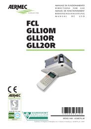
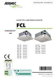
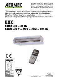
COMPONENTI PRINCIPALI MAIN DESCRIPTION PRINCIPAUX COMPOSANTS<br />
HAUPTKOMPONENTEN COMPONENTES PRINCIPALES<br />
LFC<br />
7<br />
1<br />
1 Scatola elettrica<br />
2 Ventilatore<br />
3 Motore ventilatore<br />
4 Struttura portante<br />
5 Batteria di scambio termico<br />
16<br />
9 8<br />
1 Electric box<br />
2 Fan<br />
3 Fan motor<br />
4 Load-bearing structure<br />
5 Thermal exchange battery<br />
1 Armoire électrique<br />
2 Ventilateur<br />
3 Moteur ventilateur<br />
4 Structure portante<br />
5 Batterie d'échange thermique<br />
6<br />
1 Schaltkasten<br />
2 Ventilator<br />
3 Motor des Ventilators<br />
4 Trägerstruktur<br />
5 Wärmetauscher für den thermischen Austausch<br />
1 Caja eléctrica<br />
2 Ventilador<br />
3 Motor ventilador<br />
4 Estructura portante<br />
5 Batería de intercambio térmico<br />
4<br />
10<br />
6 Valvola fiato aria batteria<br />
7 Collegamenti idraulici<br />
8 Valvola di scatico batteria<br />
9 Scarico condensa<br />
10 BCL10 (accessorio)<br />
6 Battery air breather valve<br />
7 Water connections<br />
8 Battery drain valve<br />
9 Condensate drain<br />
10 BCL10 (accessory)<br />
6 Vanne d'échappement air batterie<br />
7 Raccordements eau<br />
8 Vanne d'échappement batterie<br />
9 Evacuation des condensats<br />
10 BCL10 (accessoire)<br />
3<br />
6 Ventil für die Belüftung des Wärmetauscher<br />
7 Hydraulikanschlüsse<br />
8 Ventil zum Entladen des Wärmetauscher<br />
9 Auslass für Kondenswasser<br />
10 BCL10 (Zubehör)<br />
6 Válvula de escape aire batería<br />
7 Conexiones hidráulicas<br />
8 Válvula de descarga batería e<br />
9 Descarga del agua de condensación<br />
10 BCL10 (accesorio)<br />
2<br />
5<br />
fig. 1
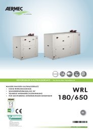
DATI DIMENSIONALI DIMENSIONS DIMENSIONS ABMESSUNGEN DIMENSIONES [mm]<br />
LFC + BCL10<br />
C<br />
LFC 1240 - 1440<br />
C'<br />
B'<br />
B<br />
A'<br />
B<br />
BCL 10<br />
A<br />
C BCL 10<br />
A<br />
B<br />
C<br />
Raccordi 4R/5R attacchi Sx attacchi Dx<br />
Connections 4R/5R left connections right connections<br />
Raccords 4R/5R ø raccords gauche raccords droit<br />
Anschlüsse 4R/5R Anschlüsse links Anschlüsse rechts<br />
Racordes 4R/5R conexiones Sx conexiones Dx<br />
Uscita acqua Water outlet<br />
A 125 125<br />
18<br />
Sortie de l'eau Wasserausgang Salida agua A’ 52 220<br />
Ingresso acqua Water inlet<br />
B 182 182<br />
18<br />
Entrée de l'eau Wassereingang Entrada agua B’ 220 52<br />
Scarico condensa Condensate discharge<br />
Evacuation des condensats Ausgang für das Kondenswasser 16,5<br />
Descarga del agua de condensación<br />
LFC<br />
LFC<br />
A<br />
Mod. LFC<br />
A 1500<br />
B 303<br />
C<br />
Peso<br />
Weight<br />
549<br />
Poids<br />
Gewicht<br />
Peso<br />
kg 31<br />
C 153 153<br />
C’ 281 281<br />
fig. 2<br />
fig. 3<br />
17
DATI DIMENSIONALI DIMENSIONS DIMENSIONS ABMESSUNGEN DIMENSIONES [mm]<br />
LFC - spazi tecnici minimi minimum distances<br />
espaces techniques minimum Mindestabstände für technische Eingriffe<br />
espacios técnicos mínimos<br />
18<br />
B<br />
C<br />
D<br />
Le distanze minime si intendono senza accessori montati.<br />
The minimum distances are reported without accessories mounted<br />
Les distances minimum ne prévoient pas les accessoires montés<br />
Die Mindestabstände verstehen sich ohne Zubehör<br />
Se entiende por distancias mínimas, éstas sin accesorios montados.<br />
LFC - punti di fissaggio<br />
fastening points<br />
points de fixation<br />
Befestigungspunkte<br />
puntos de fijación<br />
A<br />
DISTANZE MINIME<br />
MINIMUM DISTANCES<br />
DISTANCES MINIMUM<br />
MINDESTABSTÄNDE<br />
DISTANCIAS MÍNIMAS<br />
A 150<br />
B 150<br />
C 150<br />
D 150<br />
fig. 4<br />
fig. 5
DATI DIMENSIONALI DIMENSIONS DIMENSIONS ABMESSUNGEN DIMENSIONES [mm]<br />
LEGENDA READING KEY LEGENDE LEGENDE LEYENDA<br />
A 549<br />
B 1519<br />
C 209<br />
D 1229<br />
E 227<br />
LFC + BCL10<br />
BCL10<br />
F 63<br />
G 190<br />
H 273<br />
K 937<br />
L 168<br />
M 160<br />
N 19<br />
O 847<br />
P 225<br />
Q 49<br />
E D<br />
B<br />
F<br />
LFC<br />
R 607<br />
S 648<br />
T 946<br />
U 1236<br />
V 79<br />
C<br />
Q<br />
A<br />
fig. 6<br />
19
DATI DIMENSIONALI DIMENSIONS DIMENSIONS ABMESSUNGEN DIMENSIONES [mm]<br />
LFC + CA4<br />
20<br />
BCL10<br />
LFC + BCL 10 + CA<br />
E D<br />
B<br />
F<br />
BCL10<br />
CA4<br />
LFC<br />
E D<br />
B<br />
F<br />
CA<br />
LFC<br />
N<br />
G<br />
C<br />
Q<br />
N<br />
G<br />
C<br />
Q<br />
R<br />
R<br />
fig. 7<br />
fig. 8
DATI DIMENSIONALI DIMENSIONS DIMENSIONS ABMESSUNGEN DIMENSIONES [mm]<br />
LFC + BCL 10 + CA/CA4 + FA 1200<br />
E<br />
B<br />
D<br />
F<br />
P<br />
BCL10<br />
D<br />
= 295 295 295 =<br />
FA1200<br />
CA/CA4<br />
FA1200<br />
CA/CA4<br />
LFC<br />
145,5 145,5<br />
N<br />
G<br />
C<br />
Q<br />
fig. 9<br />
21
DATI DIMENSIONALI DIMENSIONS DIMENSIONS ABMESSUNGEN DIMENSIONES [mm]<br />
LFC + BCL 10 + PM1200<br />
22<br />
BCL10<br />
P<br />
E D<br />
F<br />
LFC<br />
PM1200<br />
B<br />
C<br />
L<br />
N<br />
M<br />
O<br />
fig. 10
DATI DIMENSIONALI DIMENSIONS DIMENSIONS ABMESSUNGEN DIMENSIONES [mm]<br />
LFC + BCL 10 + CA/CA4 + PA1200<br />
BCL10<br />
PA1200<br />
CA/CA4<br />
E D<br />
B<br />
F<br />
LFC<br />
P<br />
N<br />
H<br />
N<br />
G<br />
C<br />
Q<br />
K<br />
fig. 11<br />
23
DATI DIMENSIONALI DIMENSIONS DIMENSIONS ABMESSUNGEN DIMENSIONES [mm]<br />
LFC + BCL 10 + CA/CA4 + FA1200 + PM1200<br />
24<br />
BCL10<br />
FA1200<br />
CA/CA4<br />
P<br />
E D<br />
B<br />
F<br />
LFC<br />
PM1200<br />
LFC - dimensione con gli accessori BCL 10 + CA/CA4 + PM1200 + PA1200<br />
dimensions with the accessories BCL 10 + CA/CA4 + PM1200 + PA1200<br />
BCL10<br />
PA1200<br />
CA/CA4<br />
P<br />
E D<br />
B<br />
F<br />
LFC<br />
PM1200<br />
P<br />
P<br />
N<br />
G<br />
C<br />
L<br />
N<br />
M<br />
N<br />
H<br />
N<br />
G<br />
C<br />
L<br />
N<br />
M<br />
T<br />
U<br />
fig. 12<br />
fig. 13
SCHEMI ELETTRICI WIRING DIAGRAMS SCHEMAS ELECTRIQUES SCHALTPLÄNE ESQUEMAS ELÉCTRICOS<br />
LEGENDA READING KEY LEGENDE LEGENDE LEYENDA<br />
CRE =Contattore resistenza elettrica Electric heater contactor<br />
Contacteur résistance eléctrique El. Heizregister-Schutz<br />
Contactor de la resistencia eléctrica<br />
IG =Interruttore generale Main switch<br />
Interupteur général Hauptschalter<br />
Interruptor general<br />
M =Morsettiera Terminal board<br />
Boitier Klemmleiste Placa de bornes<br />
MV =Motore ventilatore Fan motor Moteur ventilateur<br />
Ventilatormotor Motor del ventilador<br />
RX =Resistenza elettrica Electric heater<br />
SA<br />
Résistance électrique Elt. Heizregister<br />
Resistencia eléctrica<br />
=Sonda ambiente Room sensor Sonde ambiante<br />
Raumtemperaturfuhler Sonda ambiente<br />
SW =Sonda minima temperatura acqua<br />
Water low temperature sensor<br />
Sonde minimum temp. eau<br />
Wasserfühler<br />
Sonda temperatura mínima del agua<br />
TR =Trasformatore Transformer Transformateur<br />
Transformator Transformador<br />
TSR =Termostato a riarmo automatico<br />
Automatic resetting thermostat<br />
Thermostat à réarmement automatique<br />
Thermostat automatischer Entriegelung<br />
Termostato de rearme automático<br />
TSRM = Termostato a riarmo manuale<br />
Manual resetting thermostat<br />
Thermostat à réarmement manuel<br />
Thermostat manueller Entriegelung<br />
Termostato de rearme manual<br />
SIT = Scheda interfaccia interface card<br />
Carte d'interface Schnittstellenkarte Tarjeta interfaz<br />
VCL1 = Valvola solenoide Caldo/Freddo Solenoid valve<br />
Vanne solenoide Magnetventil Válvula solenoide<br />
L<br />
MIN<br />
M<br />
1<br />
MED<br />
MV<br />
BL RO MA GR VI NE<br />
230V 50Hz<br />
MAX<br />
N V1 V2 V3 V4 V5<br />
V1<br />
BASSA<br />
V2<br />
V3<br />
ALTA<br />
V4<br />
V5<br />
VF<br />
N<br />
VC<br />
VCL2 = Valvola solenoide caldo Solenoid valve hot<br />
Vanne magnétique chaud Magnetventil Heizbetrieb<br />
Válvula solenoide para calor<br />
VF = Valvola solenoide freddo Solenoid valve cold<br />
Vanne magnétique froid Magnetventil Kühlbetrieb<br />
Válvula solenoide para frío<br />
= Componenti non forniti Components not supplied<br />
Composants non fournis Nicht lieferbare Teile<br />
Componentes no suministrados<br />
=Collegamenti da eseguire in loco On-site wiring<br />
Raccordements à effectuer in situ<br />
*<br />
Vor Ort auszuführende Anschlüsse Cableado in situ<br />
= Componenti forniti optional Optional components<br />
Composants en option Optionsteile<br />
Componentes opcionales<br />
V1 = Minima velocità Minimun speed<br />
Vitesse minimale Mindestgeschwindigkeit<br />
Velocidad mínima<br />
V2 = Bassa velocità Low speed Basse vitesse<br />
Niedrige Geschwindigkeit Baja velocidad<br />
V3 = Media velocità Mediun <strong>fan</strong> speed<br />
Vitesse moyenne Mittlere Geschwindigkeit<br />
Velocidad media<br />
V4 = Alta velocità High speed Haute vitesse<br />
Hohe Geschwindigkeit Alta velocidad<br />
V5 = Massima velocità Maximun speed<br />
Vitesse maximale Max. Geschwindigkeit<br />
Velocidad máxima<br />
AR = Arancio Orange Orange Orange Naranja<br />
BI = Bianco White Blanc Weiss Blanco<br />
BL = Blu Blue Bleu Blau Azul<br />
GR = Grigio Grey Gris Gray Gris<br />
MA = Marrone Brown Marron Braun Marrón<br />
NE = Nero Black Noir Schwarz Negro<br />
RO = Rosso Red Rouge Rot Rojo<br />
VE = Verde Green Vert Grün Verde<br />
VI = Viola Violet Violet Violet Violeta<br />
SCHEMA DI COLLEGAMENTO MOTORE MOTOR CONNECTION DIAGRAM<br />
SCHEMA DE RACCORDEMENT MOTEUR ANSCHLUSSPLAN MOTOR<br />
ESQUEMA DE CONEXIONADO ELÉCTRICO DEL MOTOR<br />
M<br />
Le velocità disponibili sono numerate da V1 a V5<br />
Available speeds are numbered from V1 to V5<br />
Les vitesses disponibles sont numeratées de V1 à V5<br />
Die verfügbaren Drehzahlen sind von V1 zu V5<br />
Las velocidades disponibles se numeran de V1 a 5<br />
25
PX2 LFC con commutatore a distanza e alimentazione all’unità LFC<br />
LFC with remote control selector switch and power supply to the LFC unit<br />
LFC avec commutateur à distance et alimentation à l'unité LFC<br />
26<br />
Sez. 1,5mm 2<br />
L<br />
L<br />
IG L N<br />
BL<br />
230V 50Hz<br />
MIN<br />
M<br />
1<br />
BASSA<br />
MED<br />
BL<br />
MIN<br />
M<br />
1<br />
BASSA<br />
MED<br />
MV<br />
ALTA<br />
MAX<br />
N V1 V2 V3 V4 V5<br />
MV<br />
ALTA<br />
RO MA GR VI<br />
MAX<br />
N V1 V2 V3 V4 V5<br />
VF<br />
N<br />
VC<br />
NE<br />
VF<br />
M<br />
N<br />
VC<br />
M<br />
Sez. 1,5mm 2<br />
1<br />
2<br />
3<br />
4<br />
5<br />
6<br />
0<br />
1<br />
1<br />
2<br />
3<br />
4<br />
5<br />
6<br />
PX2*<br />
1<br />
* = Componenti forniti optional Optional components Composants en option Optionsteile Componentes opcionales<br />
PX2 LFC con commutatore a distanza e alimentazione al pannello comandi<br />
LFC with remote control selector switch and power supply to the control panel<br />
LFC avec commutateur à distance et alimentation au panneau de commande<br />
RO MA GR VI<br />
NE<br />
N<br />
Sez. 1,5mm 2<br />
230V 50Hz<br />
L<br />
IG<br />
Sez. 1,5mm 2<br />
2 3<br />
0<br />
1<br />
PX2*<br />
1<br />
* = Componenti forniti optional Optional components Composants en option Optionsteile Componentes opcionales<br />
2 3
PXB LFC con termostato elettronico semplificato<br />
LFC with simplified electronic thermostat<br />
LFC avec thermostat électronique simplifié<br />
PE<br />
PE<br />
Sez. 1,5mm 2<br />
Sez. 1,5mm 2<br />
L<br />
IG L N<br />
230V 50Hz<br />
L<br />
IG L N<br />
230V 50Hz<br />
BL<br />
BL<br />
MIN<br />
MIN<br />
M<br />
1<br />
M<br />
1<br />
BASSA<br />
MED<br />
MED<br />
MV<br />
RO MA GR VI<br />
BASSA<br />
ALTA<br />
MV<br />
RO MA GR VI<br />
ALTA<br />
NE<br />
MAX<br />
N V1 V2 V3 V4 V5 VF<br />
NE<br />
MAX<br />
N V1 V2 V3 V4 V5 VF<br />
N<br />
N<br />
VCL1*<br />
VC<br />
VCL1*<br />
VC<br />
M<br />
M<br />
N N L L V1 V2 V3<br />
SIT*<br />
V1 V2 V3<br />
N N L L V1 V2 V3<br />
SIT*<br />
V1 V2 V3<br />
Sez. 1,5mm 2<br />
Sez. 1,5mm 2<br />
EX<br />
SW*<br />
N<br />
N<br />
PE<br />
L<br />
Y1<br />
V3<br />
V2<br />
V1<br />
M1<br />
M2<br />
N<br />
N<br />
N<br />
PE<br />
L<br />
Y1<br />
V3<br />
V2<br />
V1<br />
M<br />
EX<br />
M<br />
SA<br />
M<br />
SW<br />
PT1<br />
0 1<br />
1 2 3<br />
DL1<br />
T °C<br />
JP1<br />
OFF/VEL<br />
SA<br />
PXB*<br />
DL2<br />
EXT INT<br />
* = Componenti forniti optional Optional components Composants en option Optionsteile Componentes opcionales<br />
PXL2ELFC con termostato elettronico multifunzione<br />
LFC with multifunctional electronic thermostat<br />
LFC avec thermostat électronique multifonction<br />
* = Componenti forniti optional Optional components Composants en option Optionsteile Componentes opcionales<br />
PXL2E*<br />
SA<br />
27
PXL4 LFC con termostato elettronico multifunzione con controllo valvole<br />
LFC with multifunctional electronic thermostat and valves control<br />
LFC avec thermostat électronique multifonction et contrôle des vannes<br />
PE<br />
28<br />
Sez. 1,5mm 2<br />
Sez. 1,5mm 2<br />
L<br />
IG L N<br />
230V 50Hz<br />
L<br />
BL<br />
IG L N<br />
230V 50Hz<br />
MIN<br />
BL<br />
MIN<br />
M<br />
1<br />
M<br />
1<br />
BASSA<br />
MED<br />
MV<br />
RO MA GR VI<br />
BASSA<br />
ALTA<br />
MED<br />
NE<br />
MAX<br />
N V1 V2 V3 V4 V5 VF<br />
RO MA GR VI<br />
VCL1*<br />
MV<br />
ALTA<br />
NE<br />
MAX<br />
N V1 V2 V3 V4 V5 VF<br />
MA<br />
BL<br />
N<br />
VCL1*<br />
VC<br />
MA<br />
BL<br />
N<br />
RO<br />
RX*<br />
VC<br />
VCL2*<br />
MA<br />
M<br />
RO<br />
MA<br />
GR<br />
IG<br />
CRE<br />
6<br />
M<br />
1<br />
1<br />
0<br />
230V 50Hz<br />
N<br />
1 TSRE C<br />
2<br />
GR<br />
L<br />
TSRM 4<br />
2<br />
5<br />
C<br />
6<br />
4 8<br />
2 6<br />
RX<br />
PE<br />
N N L L V1 V2 V3<br />
SIT*<br />
V1 V2 V3<br />
N N L L V1 V2 V3<br />
SIT*<br />
V1 V2 V3<br />
Sez. 1,5mm 2<br />
EX<br />
SW*<br />
Sez. 1,5mm 2<br />
EX<br />
SW*<br />
N<br />
N<br />
N<br />
PE<br />
L<br />
Y2<br />
Y1<br />
V3<br />
V2<br />
V1<br />
M<br />
EX<br />
M<br />
SA<br />
M<br />
SW<br />
N<br />
N<br />
N<br />
PE<br />
L<br />
Y2<br />
Y1<br />
V3<br />
V2<br />
V1<br />
M<br />
EX<br />
M<br />
SA<br />
M<br />
SW<br />
T °C<br />
OFF/VEL<br />
* = Componenti forniti optional Optional components Composants en option Optionsteile Componentes opcionales<br />
PXL4 LFC con termostato elettronico multifunzione con controllo valvola e resistenza elettrica<br />
LFC with multifunctional electronic thermostat, valve control and electric heater<br />
LFC avec thermostat électronique multifonction, contrôle de la vanne et résistance électrique<br />
T °C<br />
OFF/VEL<br />
* = Componenti forniti optional Optional components Composants en option Optionsteile Componentes opcionales<br />
PXL4*<br />
SA<br />
PXL4*<br />
SA
MANUTENZIONE MAINTENANCE MAINTENANCE WARTUNG MANTENIMIENTO<br />
Il ventilconvettore AERMEC è costruito con tecnologie moderne che ne assicurano l’efficenza ed il funzionamento nel tempo.<br />
Pertanto l’unica manutenzione che necessita è la pulizia del filtro dell’aria per avere un funzionamento ottimale del ventilconvettore<br />
e, soprattutto, per ottenere una corretta filtrazione dell’aria. È sufficiente pulire periodicamente il filtro, estraendolo dalla sua sede.<br />
Una pulizia quindicinale può essere sufficiente per ambienti non eccessivamente polverosi.<br />
The AERMEC <strong>fan</strong>coil is constructed with state of the art technology that ensures long-term efficiency and operation. The only<br />
maintenance required is to clean the air filters, which optimises the <strong>fan</strong><strong>coils</strong> operation and, above all, achieves an effective<br />
filtration of the air. It is quite sufficient to periodically wash the filter, by simply sliding it out of its housing. Cleaning every fifteen<br />
days is enough for rooms which are not excessively dusty.<br />
Le convecteur soufflant AERMEC est construit avec des technologies modernes qui garantissent son efficacité et son fonctionnement pour<br />
longtemps. C'est pourquoi, le seul entretien qu’il requiert est le nettoyage du filtre à air pour assurer un fonctionnement optimal du convecteur<br />
soufflant et surtout pour obtenir un filtrage parfait de l’air. Pour se faire, il suffit de nettoyer périodiquement le filtre en l’enlevant de<br />
son emplacement. Un nettoyage par quinzaine est suffisant pour des locaux qui ne sont pas excessivement poussiéreux.<br />
Der Gebläsekonvektor AERMEC ist nach modernen Technologien gebaut, die eine dauerhafte Leistungsfähigkeit und eine lange<br />
Standzeit gewährleisten. Für einen optimalen Betrieb des Gebläsekonvektors ist als einzige Wartung die regelmäßige Reinigung des<br />
Luftfilters erforderlich, um eine ordnungsgemäße Luftfiltration zu sichern. Der Filter ist für die Reinigung auszubauen. Eine Reinigung<br />
alle zwei Wochen ist bei nicht übermäßig staubhaltigen Räumen ausreichend.<br />
El <strong>fan</strong> coil AERMEC está construido con tecnologías modernas que aseguran su eficacia y su duración. El único mantenimiento<br />
que precisa es la limpieza del filtro de aire, operación que asegura el funcionamiento correcto del equipo y, sobre<br />
todo, la pureza del aire. Es suficiente extraer periódicamente el filtro de su alojamiento y lavarlo. En un ambiente no demasiado<br />
polvoriento puede ser suficiente una limpieza cada quince días.<br />
PER PULIRE L’UNITÀ TO CLEAN THE UNIT POUR NETTOYER L’UNITÉ REINIGUNG DES GERÄTES LIMPIEZA DEL EQUIPO<br />
Non indirizzare getti d’acqua sull’unità. Può causare scosse elettriche o danneggiare l’unità.<br />
Non usare acqua calda, sostanze abrasive o solventi; per pulire l’unità usare un panno soffice.<br />
Do not splash water on the unit. It could result in electrical shock or damage to the product.<br />
Do not use hot water, abrasive powders or strong solvents; to clean the unit use a soft cloth.<br />
Ne pas diriger de jet d’eau en direction de l’unité. Cela peut causer des chocs électriques ou endommager l’unité.<br />
Ne pas utiliser d’eau chaude, de substances abrasives ou de solvants; pour nettoyer l’unité, utiliser un chiffon doux.<br />
Keine Wasserstrahlen auf das Gerät richten, da Stromschläge oder Geräteschäden entstehen könnten. Kein heißes Wasser,<br />
Scheuermittel oder Lösungsmittel verwenden. Das Gerät mit einem weichen Tuch reinigen.<br />
No dirija chorros de agua sobre el equipo, pueden dañarlo o provocar descargas eléctricas<br />
No utilice agua caliente, sustancias abrasivas ni disolventes; limpie con un paño suave.<br />
PERICOLO: Togliere tensione prima d’iniziare le operazioni di pulizia del filtro e/o dell’unità.<br />
DANGER: Switch off power supply before cleaning filter and/or unit.<br />
DANGER: Couper la tension avant de commencer les opérations de nettoyage du filtre et/ou de l'unité.<br />
GEFAHR: Vor der Reinigung des Filters und/oder des Gerätes die Stromversorgung abschalten.<br />
PELIGRO: Desconecte la corriente eléctrica antes de comenzar a limpiar el filtro o el equipo.<br />
29
SERVIZI ASSISTENZA ITALIA<br />
VALLE D’AOSTA<br />
AOSTA<br />
PIEMONTE<br />
D.AIR di Squaiella D. & Bidoggia C. snc Via Chambery 79/7 - 10142 Torino 0117 708 112<br />
ALESSANDRIA - ASTI - CUNEO BELLISI s.r.l. Corso Savona, 245 - 14100 Asti 0141 556 268<br />
BIELLA - VERCELLI LOMBARDI SERVICES s.r.l. Via delle Industrie - 13856 Vigliano Biellese (BI) 0158 113 82<br />
NOVARA - VERBANIA (tutta la gamma esclusi split system) AIR CLIMA SERVICE di F. & C. s.a.s. Via Pertini, 9 - 21021 Angera (VA) 0331 932 110<br />
NOVARA - VERBANIA (solo split system) CI. Elle Clima snc di Benvegnù L. Via S. Anna, 6 - 21018 Sesto Calende (VA) 0331 914 186<br />
TORINO<br />
LIGURIA<br />
AERSAT TORINO snc di Borioli Secondino & C.<br />
D.AIR di Squaiella D. & Bidoggia C. snc<br />
Strada Bertolla, 163 - 10156 Torino<br />
Via Chambery 79/7 - 10142 Torino<br />
0115 611 220<br />
0117 708 112<br />
GENOVA BRINZO ANDREA Via Del Commercio, 27 1/C2 - 16167 Genova Nervi 0103 298 314<br />
IMPERIA AERFRIGO di A. Amborno e C. s.n.c . Via Z. Massa, 152/154 - 18038 Sanremo (IM) 0184 575 257<br />
LA SPEZIA TECNOFRIGO di Veracini Nandino Via Lunense, 59 - 54036 Marina di Carrara (MS) 0585 631 831<br />
SAVONA<br />
LOMBARDIA<br />
CLIMA COLD di Pignataro D. Via Risorgimento, 11 - 17031 Albenga (SV) 0182 511 76<br />
BERGAMO ESSEBI di Sironi Bruno e C. sas Via Pacinotti, 98 - 24100 Bergamo 0354 536 670<br />
BRESCIA TERMOTEC. di Vitali G. & C. s.n.c. Via G. Galilei - Trav. I°, 2 - 25010 S. Zeno S. Naviglio (BS) 0302 160 812<br />
COMO - SONDRIO - LECCO PROGIELT di Libeccio & C. s.r.l. Via Rigamonti, 21 - 22020 San Fermo della Battaglia (CO) 0315 364 23<br />
CREMONA MORETTI ALBANO & C. s.n.c. Via Manini, 2/C - 26100 Cremona 0372 461 935<br />
MANTOVA F.LLI COBELLI di Cobelli Davide & C. s.n.c. Via Tezze, 1 - 46040 Cavriana (MN) 0376 826 174<br />
CLIMA CONFORT di O. Mazzoleni Via A. Moro, 113 - 20097 S. Donato Milanese (MI) 0251 621 813<br />
MILANO - LODI - Zona cremasca<br />
CLIMA LODI di Sali Cristian<br />
CRIO SERVICE s.r.l.<br />
Via Felice Cavallotti, 29 - 26900 Lodi<br />
Via Gallarate, 353 - 20151 Milano<br />
0371 549 304<br />
0233 498 280<br />
S.A.T.I.C. di Lovato Dario Via G. Galilei, 2 int. A/2 - 20060 Cassina dè Pecchi (MI) 0295 299 034<br />
PAVIA BATTISTON GIAN LUIGI Via Liguria, 4/A - 27058 Voghera (PV) 0383 622 53<br />
VARESE (tutta la gamma esclusi split system) AIR CLIMA SERVICE di Frascati Paolo & C. snc Via Pertini, 9 - 21021 Angera (VA) 0331 932 110<br />
VARESE (solo split system)<br />
TRENTINO ALTO ADIGE<br />
CI. Elle Clima snc di Benvegnù L. Via S. Anna, 6 - 21018 Sesto Calende (VA) 0331 914 186<br />
BOLZANO - TRENTO<br />
FRIULI VENEZIA GIULIA<br />
SESTER F. s.n.c. di Sester A. & C. Via E. Fermi, 12 - 38100 Trento 0461 920 179<br />
PORDENONE CENTRO TECNICO s.n.c. di Menegazzo G. & C. Via Conegliano, 94/A - 31058 Susegana (TV) 0438 450 271<br />
TRIESTE - GORIZIA LA CLIMATIZZAZIONE TRIESTE SRL Strada della Rosandra, 269 - 34018 San Dorligo della Valle(TS) 0408 280 80<br />
UDINE<br />
VENETO<br />
S.A.R.E. di Musso Dino Corso S. Valentino, 4 - 33050 Fraforeano (UD) 0432 699 810<br />
BELLUNO FONTANA SOFFIRO FRIGORIFERI s.n.c. Via Sampoi, 68 - 32020 Limana (BL) 0437 970 042<br />
LEGNAGO DE TOGNI STEFANO Via De Nicoli, 2 - 37045 Legnago (VR) 0442 203 27<br />
PADOVA CLIMAIR s.a.s. di F. Cavestro & C. Via Austria, 21 - Z.I. - 35127 Padova 0497 723 24<br />
ROVIGO FORNASINI MAURO Via Sammartina, 18/A - 44040 Chiesuol del Fosso (FE) 0532 978 450<br />
TREVISO CENTRO TECNICO di Menegazzo s.r.l. Via Conegliano, 94/A - 31058 Susegana (TV) 0438 450 269<br />
VENEZIA (zona centro città) SIMIONATO GIANNI Via Trento, 29 - 30174 Mestre (VE) 0419 598 88<br />
VENEZIA (provincia escluso il centro città) S.M. s.n.c. di Spolaore Andrea e Musner Maurizio Via Fapanni 41/D - 30030 Martellago (VE) 0415 402 047<br />
VERONA (escluso LEGNAGO) ALBERTI FRANCESCO Via Tombetta, 82 - 37135 Verona 0455 094 10<br />
VICENZA (solo split system) ASSICLIMA di Colpo Donato Via Capitello, 63/c - 36010 Cavazzale (VI) 3368 139 63<br />
VICENZA (tutta la gamma esclusi split system)<br />
EMILIA ROMAGNA<br />
BIANCHINI GIOVANNI & IVAN snc Via G. Galilei, 1Z - Loc. Nogarazza - 36057 Arcugnano (VI) 0444 569 481<br />
BOLOGNA EFFEPI s.n.c. di Ferrazzano & Proto Via I° Maggio, 13/8 - 40044 Pontecchio Marconi (BO) 0516 781 146<br />
FERRARA FORNASINI MAURO Via Sammartina, 18/A - 44040 Chiesuol del Fosso (FE) 0532 978 450<br />
FORLÌ - RAVENNA - RIMINI ALPI GIUSEPPE Via N. Copernico, 100 - 47100 Forlì 0543 725 589<br />
MODENA (zona Modena Sud) AERSAT s.n.c. di Leggio M. & Lolli S. Piazza Beccadori, 19 - 41057 Spilamberto (MO) 0597 829 08<br />
MODENA (zona Modena Nord) CLIMASERVICE di Golinelli Ste<strong>fan</strong>o Via Per Modena, 18/E - 41034 Finale Emilia (MO) 0535 921 56<br />
PARMA<br />
ALFATERMICA s.n.c. Galbano & Biondo<br />
BENASSI GRAZIANO<br />
Via Mantova, 161 - 43100 Parma<br />
Via Paisello, 8 - 43100 Parma<br />
0521 776 771<br />
0521 460 744<br />
PIACENZA MORETTI ALBANO & C. s.n.c. Via Manini, 2/C - 26100 Cremona 0372 461 935<br />
REGGIO EMILIA<br />
TOSCANA<br />
ECOCLIMA S.r.l. Via Maestri del lavoro, 14 - 42100 Reggio Emilia 0522 558 709<br />
AREZZO CLIMA SERVICE ETRURIA s.n.c. Via G. Caboto, 69/71/73/75 - 52100 Arezzo 0575 900 700<br />
FIRENZE - PRATO S.E.A.T. SERVIZI TECNICI srl Via Aldo Moro, 25 - 50019 Sesto Fiorentino (FI) 0554 255 721<br />
GROSSETO ACQUA e ARIA SERVICE s.r.l. Via D. Lazzaretti, 8A - 58100 Grosseto 0564 410 579<br />
LIVORNO - PISA SEA s.n.c. di Rocchi R. & C. Via dell’Artigianato, Loc.Picchianti - 57121 Livorno - 0586 426 471<br />
LUCCA - PISTOIA FRIGOTEC. s.n.c. G. & MC. BENEDETTI Via V. Civitali, 2 - 55100 Lucca 0583 491 089<br />
MASSA CARRARA TECNOFRIGO di Veracini Nandino Via Lunense, 59 - 54036 Marina di Carrara (MS) 0585 631 831<br />
SIENA (tutta la gamma esclusi split system) FRIGOTECNICA SENESE s.n.c. di B. & C. Strada di Cerchiaia, 42 - Z.A. 53100 Siena 0577 284 330<br />
SIENA (split system)<br />
MARCHE<br />
GLOBAL IMPIANTI SENESE srl Strada Massetana Romana, 52 - 53100 Siena 0577 247 406<br />
ANCONA - PESARO AERSAT snc di Marchetti S. & Sisti F. Via M. Ricci, 16/A - 60020 Palombina (AN) 0718 894 35<br />
MACERATA - ASCOLI PICENO<br />
UMBRIA<br />
CAST s.n.c. di Antinori-Cardinali & R. Via D. Alighieri, 68 - 62010 Morrovalle (MC) 0733 865 271<br />
PERUGIA A.I.T. s.r.l. Via dell’industria, Z.I. Molinaccio - 06154 Ponte S. Giovanni (PG) 0755 990 564<br />
TERNI<br />
ABRUZZO<br />
CAPOCCETTI OTELLO Via G. Medici, 14 - 05100 Terni 0744 277 169<br />
CHIETI - PESCARA - TERAMO<br />
L’AQUILA - ISERNIA - CAMPOBASSSO<br />
LAZIO<br />
PETRONGOLO DINO Via Torremontanara, 30 - 66010 Torre Vecchia Teatina (CH) 0871 360 311<br />
FROSINONE - LATINA MASTROGIACOMO AIR SERVICE - M. C. P.zza Berardi, 16 - 03023 Ceccano (FR) 0775 601 403<br />
RIETI CAPOCCETTI OTELLO Via G. Medici, 14 - 05100 Terni 0744 277 169<br />
(solo split system) DUEG CLIMA di Giulio Giornalista Via Chitignano, 12B - 00138 Roma 0688 130 20<br />
ROMA (solo split system) MARCHIONNI MARCO P.zza dei Bossi, 16 - 00172 Centocelle (RM) 0623 248 850<br />
(tutta la gamma esclusi split system)TAGLIAFERRI 2001 s.r.l. Via Guidonia Montecelio snc - 00191 Roma 0633 312 34<br />
VITERBO<br />
CAMPANIA<br />
AIR FRIGO di Massimo Piacentini Viale Baccelli, 74 - 00053 Civitavecchia (RM) 0766 541 945<br />
AVELLINO - SALERNO SAIT s.r.l. Via G. Deledda, 10 - 84010 San Marzano sul Sarno (SA) 0815 178 451<br />
CAPRI CATALDO COSTANZO Via Tiberio, 7/F - 80073 Capri (NA) 0818 378 479<br />
NAPOLI - CASERTA - BENEVENTO<br />
PUGLIA<br />
AERCLIMA Sud s.n.c. di Fisciano Carmelo & C. Via Nuova Toscanella, 34/c - 80145 Napoli 0815 456 465<br />
BARI KLIMAFRIGO s.r.l. Via Vallone, 81 - 70121 Bari 0805 538 044<br />
FOGGIA CLIMACENTER di Amedeo Nardella Via Carmicelli, 29 Pal. A Sc. A - 71016 San Severo (FG) 3396 522 443<br />
LECCE - BRINDISI GRASSO VINCENZO Zona P.I.P. - Lotto n. 38 - 73052 Parabita (LE) 0833 595 267<br />
TARANTO<br />
BASILICATA<br />
ORLANDO PASQUALE Via Vespucci, 5 - 74023 Grottaglie (TA) 099 5 639 823<br />
MATERA - POTENZA<br />
MOLISE<br />
AERLUCANA di A. Scalcione Via Dei Peucezi, 23 - 75100 Matera 0835 381 467<br />
CAMPOBASSO - ISERNIA<br />
CALABRIA<br />
PETRONGOLO DINO Via Torremontanara, 30 - 66010 Torre Vecchia Teatina (CH) 0871 360 311<br />
CATANZARO - COSENZA - CROTONE A.E.C. di Ranieri Annarita Via B. Miraglia, 72 - 88100 Catanzaro 0961 771 123<br />
REGGIO CALABRIA REPACI ANTONINO Via Militare 2nda Trav. 8D - 89053 Catona (RC) 0965 301 431<br />
REGGIO CALABRIA - VIBO VALENTIA<br />
SICILIA<br />
MANUTENSUD di Antonio Amato Via F. Cilea, 62 - 88065 Guardavalle (CZ) 0967 865 16<br />
CATANIA - MESSINA GIUFFRIDA GIUSEPPE Via Mandrà, 15/A - 95124 Catania 0953 514 85<br />
ENNA - CALTANISSETTA - AGRIGENTO FONTI FILIPPO Viale Aldo Moro, 141 - 93019 Sommatino (CL) 0922 871 333<br />
PALERMO - TRAPANI S.E.A.T. di A. Parisi & C. s.n.c. Via T. Marcellini, 7 - 90135 Palermo 0915 917 07<br />
SIRACUSA - RAGUSA<br />
SARDEGNA<br />
FINOCCHIARO ANTONINO Via Paternò, 71 - 96100 Siracusa 0931 756 911<br />
CAGLIARI - ORISTANO MUREDDU L. di Mureddu Pasquale Via Garigliano, 13 - 09122 Cagliari 0702 846 52<br />
SASSARI - NUORO POSADINU SALVATORE IGNAZIO Z.I. Predda Niedda - Sud - Strada 11 - 07100 Sassari 0792 612 34
Aermec partecipa al Programma di Certificazione EUROVENT. I prodotti interessati figurano nella Guida EUROVENT dei Prodotti Certificati.<br />
Aermec is partecipating in the EUROVENT Certification Programme. Products are as listed in the EUROVENT Directory of Certified Products.<br />
Aermec partecipe au Programme de Certification EUROVENT. Les produits figurent dans l’Annuaire EUROVENT des Produits Certifiés.<br />
Aermec ist am Zertifikations - Programm EUROVENT beteiligt. Die entsprechend gekennzeichneten Produkte sind im EUROVENT - Jahrbuch aufgefürt.<br />
AERMEC S.p.A. participa en el programa de certificación EUROVENT. Sus equipos aparecen en el directorio de productos certificados EUROVENT.<br />
AERMEC S.p.A.<br />
I-37040 Bevilacqua (VR) - Italia<br />
Via Roma, 44 - Tel. (+39) 0442 633111<br />
Telefax (+39) 0442 93730 - (+39) 0442 93566<br />
www.aermec.com