UNITÀ TRATTAMENTO ARIA AIR HANDLING UNIT VENTILO ...
UNITÀ TRATTAMENTO ARIA AIR HANDLING UNIT VENTILO ...
UNITÀ TRATTAMENTO ARIA AIR HANDLING UNIT VENTILO ...

You also want an ePaper? Increase the reach of your titles
YUMPU automatically turns print PDFs into web optimized ePapers that Google loves.
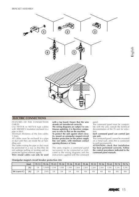
BRACKET ASSEMBLY<br />
ELECTRIC CONNECTIONS<br />
FEATURES OF THE CONNECTION<br />
CABLES<br />
Use H05V-K or N07V-K type cables<br />
with 300/500 V insulation enclosed in a<br />
pipe or duct.<br />
Minimum thickness of the line cable:<br />
1.5mm.<br />
All cables must be enclosed in a pipe<br />
or duct until they are inside the air handling<br />
unit.<br />
The cables exiting the pipe or duct must<br />
be positioned in a way so that they do<br />
not undergo pulling or twisting and are<br />
protected against external agents.<br />
Wire strand cables can only be used<br />
Omnipolar magnet-circuit breaker protection (IM)<br />
� � �<br />
� �<br />
with a tag board. Ensure that the wire<br />
strands are introduced correctly.<br />
The wiring diagrams are subject to continuous<br />
updating, it is therefore compusory<br />
to refer to that on the machine.<br />
To protect the unit against short circuits,<br />
mount an omnipolar magnet-circuit<br />
breaker protection on the power supply<br />
line (see table), with minimum contact<br />
opening distance of 3mm.<br />
The units require a command panel<br />
(accessory) to be connected as indicated<br />
in the wiring diagrams and the<br />
instructions supplied with the command<br />
panel.<br />
The command panel must be compatible<br />
with the unit, consult the technical<br />
documentation of the TS unit for selection.<br />
Each command panel can control just<br />
one unit.<br />
The command panel cannot be mounted<br />
on a metal wall, unles this is connected<br />
to earth permanently .<br />
ATTENTION: check that installation<br />
has been performed correctly. Follow<br />
the control procedures indicated in the<br />
command panel manuals.<br />
Mod. TS 13 TS 16 TS 23 TS 34 TS 36 TS 43 TS 46 TS 53 TS 56 TS 63 TS 74 TS 76<br />
[A] 1A 1,9A% 1,9A 1,9A 1,9A 2,6A 2,6A 2,6A 2,6A 3,9A 5,5A 5,5A<br />
IM (curve C) [A] 2A 2A% 3A 3A 3A 4A 4A 4A 4A 6A 8A 8A<br />
15<br />
English