ventilconvettori fan coil ventilo-convecteurs gebläsekonvektoren ...
ventilconvettori fan coil ventilo-convecteurs gebläsekonvektoren ...
ventilconvettori fan coil ventilo-convecteurs gebläsekonvektoren ...

You also want an ePaper? Increase the reach of your titles
YUMPU automatically turns print PDFs into web optimized ePapers that Google loves.
VENTILCONVETTORI<br />
FAN COIL<br />
VENTILO-CONVECTEURS<br />
GEBLÄSEKONVEKTOREN<br />
FCX<br />
Sostituisce - Replace<br />
Remplace - Ersetzt:<br />
64560.39/0005<br />
IFCXFX<br />
0201<br />
64560.52<br />
MANUALLE DII FUNZZZIOOONAMEENTTOOO • DIIIRECCCTTTIOOONSSS FOOOR USSSE<br />
MAANUELL DDE FOOONCTTTIOOONNEEMEENTTT BEEEDIIIENUNGGGSSSANLEEEITTTUNG
INDICE INDEX INDEX INHALTSVERZEICHNIS<br />
FCX - A<br />
Funzionamento • Operation Fonctionnement Betrieb 3<br />
FCX - ACB<br />
Funzionamento Operation Fonctionnement Betrieb 4<br />
FCX - ACT<br />
Funzionamento Operation Fonctionnement Betrieb 5<br />
Utilizzo Use 6<br />
Utilisation Betrieb 7<br />
Caratteristiche di funzionamento Operation 8<br />
Caracteristiques des fonctionnement Einsatzcharakteristik 9<br />
Configurazione Setting 10<br />
Configuration Konfiguration 11<br />
Autotest 12<br />
USI IMPROPRI IMPROPER USES USAGES IMPROPES UNSACHGEMÄßER GEBRAUCH<br />
MANUTENZIONE MEINTENANCE ENTRETIEN WARTUNG 13<br />
PROBLEMA - PROBABILE CAUSA - SOLUZIONE<br />
ROBLEM - PROBABLE CAUSE - REMEDY<br />
PROBLEME - CAUSE PROBABLE - SOLUTION<br />
PROBLEM - MÖGLICHE URSACHE - ABHILFE 14
FUNZIONAMENTO FCX - A • FCX - A OPERATION<br />
FONCTIONNEMENT DU FCX - A BETRIEB DER FCX - A<br />
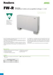
Commutatore manuale (versione A)<br />
Manual switch (A version)<br />
Commande standard (version A)<br />
Standard Fernbedienung (version A)<br />
a) Per accendere/spegnere il ventilconvettore:<br />
Commutare la posizione del selettore superiore.<br />
To turn on/off the <strong>fan</strong> <strong>coil</strong>:<br />
Shift the upper button. On the remote panel with<br />
Pour allumer/eteindre le ventilconvecteur:<br />
Pouser le bouton du haut. Sur le panneau avec<br />
Einschalten/Ausschalten des Gebläsekonvektors:<br />
Die Stellung des oberen Schiebers ändern. Auf der mit<br />
b) Per scegliere la velocità del ventilatore<br />
To select <strong>fan</strong> <strong>coil</strong> speed<br />
Pour choisir la vitesse du ventilateur<br />
Ventilatorgeschwindigkeit wählen<br />
3<br />
FFCXX --- AA
FCXXX - ACB<br />
FUNZIONAMENTO FCX - ACB FCX - ACB OPERATION<br />
FONCTIONNEMENT DU FCX - ACB BETRIEB DER FCX - ACB<br />
Termostato elettronico a funzioni ridotte (versione ACB)<br />
Reduced-function electronic thermostat (ACB version)<br />
Thermostat électronique à fonctions réduites (version ACB)<br />
Elektronischer Thermostat mit eingeschränkten Funktionen (version ACB)<br />
a) Per accendere/spegnere il ventilconvettore:<br />
1) Aprire la griglia di destra del ventilconvettore per accedere al pannello comandi.<br />
2) Commutare la posizione del selettore superiore:<br />
si accende/spegne la spia rossa.<br />
To turn on/off the <strong>fan</strong> <strong>coil</strong>:<br />
1) Open the <strong>fan</strong><strong>coil</strong> right grille to reach the control panel.<br />
2) Change over the upper button: red goes on/off.<br />
Pour allumer/éteindre le <strong>ventilo</strong>convecteur:<br />
1) Ouvrir la grille à droit du <strong>ventilo</strong>convecteur pour atteindre le panneau commandes.<br />
2) Pousser le bouton du haut:<br />
le témoin rouge s’allume/s’éteint.<br />
Einschalten/Ausschalten des Gebläsekonvektors:<br />
1) Um den thermostats zu betätigen, Das rechte Gitter öffnen.<br />
2) Die obene taste rüecken:<br />
leuchtet/erlöscht die rote Lampe auf.<br />
b) Per scegliere il funzionamento - To select operating mode<br />
Pour choisir le mode fonctionnement - Betriebsmodus anwählen<br />
Inverno Winter<br />
Hiver Winter<br />
c) Per scegliere la velocità del ventilatore<br />
To select <strong>fan</strong> <strong>coil</strong> speed<br />
Pour choisir la vitesse du ventilateur<br />
Ventilatorgeschwindigkeit wählen<br />
Estate Summer<br />
Eté Sommer<br />
d) Per impostare la temperatura: ruotare la manopola verso la zona blu per un’azione di raffreddamento e<br />
verso quella rossa per un’azione di riscaldamento.<br />
La spia gialla vicino alla manopola indica il tipo di funzionamento (spenta se l’unità non è in funzione,<br />
accesa se è in funzionamento).<br />
To set the temperature: turn the knob towards the blue zone in order to cool or towards the red zone in<br />
order to heat.<br />
The yellow pilot light near the knob shows the operation mode (off, if the unit is not working; on, if it is<br />
working).<br />
Pour programmer la température: tourner le bouton vers la zone bleue pour une action de refroidissement<br />
et vers la zone rouge pour une action de chauffage.<br />
Le voyant jaune près du bouton indique le type de fonctionnement (il est éteint si l’unité n’est pas en marche; il est allumé si<br />
l’unité est en fonction).<br />
Für die Temperatureinstellung: den Bedienungsknopf gegen den blauen Bereich für den Kühlbetrieb und gegen den roten<br />
Bereich für den Heizbetrieb drehen.<br />
Die gelbe Kontrollampe in der Nähe des Bedienungsknopfes zeigt die Betriebsart an (kein Aufleuchten bei ausgeschalteter Einheit,<br />
ein Aufleuchten im Betrieb).<br />
4
FUNZIONAMENTO FCX - ACT FCX - ACT OPERATION<br />
FONCTIONNEMENT DU FCX - ACT BETRIEB DER FCX - ACT<br />
Il pannello comandi è alloggiato sotto lo sportellino con griglia<br />
a destra o a sinistra del ventilconvettore (fig. 4).<br />
Il pannello può essere protetto da manomissioni, bloccando<br />
con una vite lo sportellino di copertura.<br />
Il termostato di regolazione controlla il funzionamento del ventilconvettore<br />
per mantenere nell’ambiente la temperatura impostata.<br />
Il modo di funzionamento in riscaldamento o in raffreddamento,<br />
avviene in modo automatico (cambio stagione) e dipende dalla<br />
temperatura dell’acqua circolante nell’impianto.<br />
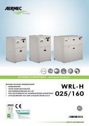
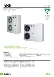
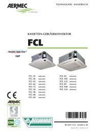
Il pannello comprende (fig. 1):<br />
–(A) selettore acceso-spento e modo di ventilazione;<br />
–(B) selettore della temperatura;<br />
–(C) led indicatore del modo di funzionamento (blu,<br />
rosso e fucsia);<br />
–(D) led giallo indicatore di richiesta ventilazione<br />
(o anomalie di funzionamento se lampeggiante).<br />
Le panneau de commande se trouve sous le volet à grille, à<br />
droite ou à gauche du <strong>ventilo</strong>-convecteur (fig. 4).<br />
Le panneau peut être protégé contre les manipulations en bloquant<br />
le volet de couverture à l'aide d'une vis.<br />
Le thermostat de régulation contrôle le fonctionnement du<br />
<strong>ventilo</strong>-convecteur, de façon à maintenir constante la température<br />
programmée dans la pièce.<br />
Le mode de fonctionnement Chauffage ou Rafraîchissement se<br />
fait automatiquement (changement de saison) et il dépend de<br />
la température de l'eau qui circule dans l'installation.<br />
Le panneau comprend (fig. 1):<br />
-(A) sélecteur marche-arrêt et mode de ventilation;<br />
-(B) sélecteur de la température;<br />
-(C) led indiquant le mode de fonctionnement (bleu,<br />
rouge et fuchsia);<br />
-(D) led jaune indiquant une demande de ventilation<br />
(ou des anomalies de fonctionnement si elle clignote).<br />
Fig.1<br />
B<br />
C<br />
A<br />
-<br />
+<br />
D<br />
The control panel is located under the door with grid on the<br />
left or right-hand side of the <strong>fan</strong><strong>coil</strong> (fig. 4).<br />
To prevent tampering with unit controls, secure the door with<br />
a screw.<br />
The thermostat controls the operation of the <strong>fan</strong><strong>coil</strong>, which is<br />
regulated to maintain the temperature setting.<br />
The unit operating mode switches automatically between heating<br />
and cooling (season change), depending on the temperature<br />
of the water in the system.<br />
The panel features (fig. 1):<br />
-(A) ON/OFF and ventilation mode selector switch;<br />
-(B) temperature selector switch;<br />
-(C) operating mode LED indicator lamp (blue, red and<br />
pink);<br />
-(D) ventilation request yellow LED lamp (also indicates<br />
operating fault when flashing).<br />
Das Bedienteil ist unter der Klappe mit Ausströmgitter rechts<br />
oder links am Gebläsekonvektor angeordnet (Abb. 4).<br />
Es kann durch Sichern der Klappe mit einer Schraube gegen<br />
unbefugtes Verstellen geschützt werden.<br />
Der Temperaturregler steuert den Betrieb des<br />
Gebläsekonvektors so, dass die eingestellte Raumtemperatur<br />
konstant gehalten wird.<br />
Die Einschaltung der Betriebsart Heizen oder Kühlen erfolgt<br />
automatisch (Umschaltung von Heizen/Kühlen) in Funktion<br />
der Temperatur des in der Anlage zirkulierenden Wassers.<br />
Auf dem Bedienteil sind folgende Elemente angeordnet (Abb. 1):<br />
-(A) Wahlschalter Ein/Aus und Gebläsebetrieb;<br />
-(B) Temperaturschalter;<br />
-(C) Anzeige-Led der Betriebsart (blau, rot und<br />
fuchsia);<br />
-(D) Gelbe Led zur Anzeige der Anforderung des<br />
Gebläsebetriebs (oder Betriebsstörungen bei Blinken).<br />
V1 =Velocità minima<br />
Minimun <strong>fan</strong> speed<br />
Vitesse minimale<br />
Mindestgeschwindigkeit<br />
V2 =Velocità media<br />
Mediun <strong>fan</strong> speed<br />
Vitesse moyenne<br />
Mittlere Geschwindigkeit<br />
V3 =Velocità massima<br />
Maximun <strong>fan</strong> speed<br />
Vitesse maximale<br />
Höchstgeschwindigkeit<br />
5<br />
FFCXXX -- AACTT
FCCX - AACTTT<br />
UTILIZZO (FCX-ACT)<br />
COMANDI:<br />
Selettore della Velocità (A)<br />
OFF Il ventilconvettore è spento. Può però<br />
ripartire in modalità Caldo (funzione Antigelo)<br />
se la temperatura ambiente diventa inferiore a<br />
8°C e la temperatura dell’acqua è idonea, in<br />
questo caso il led rosso lampeggia.<br />
AUTO Il termostato mantiene la temperatura<br />
impostata cambiando la velocità del ventilatore<br />
in Modo Automatico, in funzione della temperatura<br />
ambiente e di quella impostata.<br />
Il termostato mantiene la temperatura<br />
impostata mediante cicli di accensione<br />
e spegnimento, utilizzando rispettivamente la<br />
velocità minima, media o massima del ventilatore.<br />
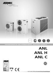
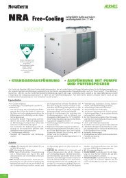
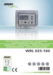
Selettore della Temperatura (B)<br />
Consente di impostare la temperatura desiderata<br />
(fig. 3).<br />
La temperatura corrispondente al selettore B<br />
impostato nella posizione centrale (fig. 5),<br />
dipende dal modo di funzionamento attivo<br />
-<br />
+<br />
(Caldo 20°C, Freddo 25°C, Antigelo 8°C). C<br />
Le differenze di temperatura massima e minima<br />
rispetto alla posizione centrale sono +8°C e -8°C<br />
D<br />
Cambio stagione<br />
Il ventilconvettore FCX- ACT imposta automaticamente<br />
il funzionamento a Caldo o a Freddo<br />
in funzione delle temperature dell’acqua nell’impianto;<br />
per impostazioni particolari è possibile il cambio stagione<br />
agendo sul selettore temperatura.<br />
Visualizzazioni luminose<br />
Il led C cambia di colore per indicare il modo di funzionamento<br />
attivo:<br />
ROSSO Caldo (riscaldamento),<br />
BLU Freddo (raffreddamento),<br />
FUCSIA lampeggiante indica che l’acqua nell’impianto non<br />
ha ancora raggiunto la temperatura idonea per<br />
abilitare la ventilazione,<br />
GIALLO acceso indica che la richiesta di ventilazione è attiva;<br />
lampeggiante indica una anomalia di funzionamento<br />
della sonda ambiente (Modo Emergenza).<br />
A<br />
-<br />
USE (FCX-ACT)<br />
CONTROLS:<br />
Speed selector switch (A)<br />
OFF The <strong>fan</strong><strong>coil</strong> is off, though will restart in<br />
heating mode (antifreeze function) if room temperature<br />
drops below 8°C and water tempera-<br />
+ ture is suitable; in this case, the red LED lamp<br />
will flash.<br />
AUTO The thermostat maintains temperature of<br />
the setting by adjusting <strong>fan</strong> speed in automatic<br />
mode, according to the room temperature and<br />
the temperature setting.<br />
The thermostat maintains the temperature<br />
of the setting by on-off cycles,<br />
Fig. 2<br />
using minimum, medium and maximum <strong>fan</strong><br />
speeds as required.<br />
Fig. 3<br />
Fig. 4<br />
6<br />
Temperature selector switch (B)<br />
Use to make the required temperature setting<br />
(fig. 3).<br />
The temperature at the central position (fig. 5)<br />
will depend on the current operating mode<br />
(Heating 20°C, Cooling 25°C, Antifreeze 8°C).<br />
The maximum temperature deviations from the<br />
central position are +8°C and -8°C<br />
Season change<br />
The FCX-ACT <strong>fan</strong><strong>coil</strong> automatically sets to<br />
Heating or Cooling mode according to the temperature<br />
of the water circulating through the<br />
unit. In special cases, season change can be made by adjusting<br />
the temperature selector switch.<br />
Displays<br />
The LED indicator lamp C changes colour to indicate the<br />
current operating mode:<br />
RED Heating,<br />
BLUE Cooling,<br />
PINK When flashing, water in unit has not yet reached<br />
temperature required to enable ventilation,<br />
YELLOW Ventilation request is activated. When flashing,<br />
an ambient probe operating fault has been detected<br />
(Emergency mode).
UTILISATION (FCX-ACT)<br />
COMMANDES:<br />
Sélecteur de la Vitesse (A)<br />
OFF Le <strong>ventilo</strong>-convecteur est éteint. Il peut<br />
toutefois repartir en mode Chauffage (fonction<br />
Antigel) si la température ambiante s'abaisse<br />
au-dessous de 8°C et que la température de -<br />
l'eau est appropriée; dans ce cas, la led rouge<br />
se met à clignoter.<br />
AUTO Le thermostat maintient la température<br />
programmée en modifiant la vitesse du ventilateur<br />
en Mode Automatique, en fonction de la tempéra- A<br />
ture ambiante et de la température programmée.<br />
Le thermostat maintient la température<br />
programmée en exécutant des<br />
cycles d'allumage et d'arrêt et en utilisant<br />
respectivement la vitesse minimale, moyenne ou maximale<br />
du ventilateur.<br />
Sélecteur de la Température (B)<br />
Il permet de programmer la température désirée<br />
(fig. 3).<br />
La température correspondant au sélecteur réglé<br />
sur la position centrale (fig. 5) dépend du mode<br />
B -<br />
de fonctionnement actif (Chaud 20°C, Froid<br />
25°C, Antigel 8°C).<br />
Les différences de température maximale et<br />
minimale par rapport à la position centrale sont<br />
+8°C et -8°C.<br />
Changement de saison<br />
Le <strong>ventilo</strong>-convecteur FCX- ACT règle automatiquement<br />
le fonctionnement en Chauffage ou<br />
Rafraîchissement en fonction de la température<br />
de l'eau présente dans l'installation; pour des réglages particuliers,<br />
le changement de saison est possible en agissant sur<br />
le sélecteur de température.<br />
Visualisations lumineuses<br />
La led C change de couleur pour indiquer le mode de fonctionnement<br />
actif:<br />
ROUGE Chaud (chauffage),<br />
BLEU Froid (rafraîchissement),<br />
FUCHSIA Si la led clignote, elle indique que l'eau présente<br />
dans l'installation n'a pas encore atteint la température<br />
appropriée pour valider la ventilation,<br />
JAUNE allumée, la led indique que la demande de ventilation<br />
est active;<br />
elle clignote pour indiquer une anomalie de fonctionnement<br />
de la sonde ambiante (Mode Urgence).<br />
Riscaldamento Heating<br />
Chaud Warm<br />
20°C<br />
-<br />
+<br />
12°C 28°C<br />
C D<br />
Fig. 2<br />
C D<br />
Fig. 3<br />
Raffreddamento Cooling<br />
Froid Kalt<br />
25°C<br />
-<br />
+<br />
17°C<br />
C D<br />
33°C<br />
GEBRAUCH (FCX-ACT)<br />
Bedienteile:<br />
Drehzahl-Wahlschalter (A)<br />
OFF Der Gebläsekonvektor ist ausgeschaltet.<br />
Er wird wieder in der Betriebsart Heizen<br />
(Einfrierschutz-Funktion) eingeschaltet, sobald<br />
+ die Raumtemperatur unter 8 °C abfällt und die<br />
Wassertemperatur dies zulässt. In diesem Fall<br />
blinkt die rote Led-Diode.<br />
AUTO Der Temperaturregler hält die eingestellte<br />
Temperatur durch Regelung der<br />
Gebläsedrehzahl im Automatikbetrieb in<br />
Funktion von Raumtemperatur und eingestelltem<br />
Temperatur-Sollwert konstant.<br />
Der Temperaturregler hält den eingestellten<br />
Temperatur-Sollwert durch zyklisches<br />
Ein- und Ausschalten konstant, er setzt dazu entweder die<br />
unterste, die mittlere oder die höchste Gebläsedrehzahl ein.<br />
Temperaturschalter (B)<br />
Dieser Schalter dient zur Einstellung der gewünschten<br />
Raumtemperatur (Abb. 3).<br />
Die Temperatur bei Mittelstellung des<br />
Wahlschalters (Abb. 5) ist von der jeweils akti-<br />
+<br />
ven Betriebsart abhängig (Heizen 20 °C,<br />
Kühlen 25 °C, Einfrierschutz 8 °C).<br />
Die Differenz der höchsten und niedrigsten<br />
Temperatur zur Mittelstellung beträgt +8 °C<br />
und -8 °C.<br />
Umschaltung Kühl-/Heizbetrieb<br />
Der Gebläsekonvektor FCX-ACT schaltet selbsttätig<br />
in Funktion der Wassertemperaturen in<br />
der Anlage die Betriebsart Heizen oder Kühlen<br />
ein. Für spezielle Einstellungen kann die Umschaltung von<br />
Kühl-/Heizbetrieb mit dem Temperaturschalter vorgenommen<br />
werden.<br />
Leuchtanzeigen<br />
Die Led-Diode C zeigt die jeweils aktive Betriebsart durch<br />
eine Farbänderung an:<br />
ROT Heizen (Heizung);<br />
BLAU Kühlen (Kühlung);<br />
FUCHSIA Durch Blinken wird angezeigt, dass die Wasserfüllung<br />
der Anlage noch nicht die zur Einschaltung des<br />
Gebläses erforderliche Temperatur erreicht hat.;<br />
GELB Zeigt durch Leuchten an, dass der Betrieb des<br />
Gebläses angefordert wurde.<br />
Blinken zeigt eine Funktionsstörung des<br />
Raumfühlers an (Notbetrieb).<br />
FROST PROTECTION<br />
8°C<br />
-<br />
+<br />
8°C 8°C<br />
C D<br />
Fig. 5<br />
7<br />
FFCXXX -- AACTT
FCCCX - ACTTT<br />
CARATTERISTICHE DI FUNZIONAMENTO<br />
I <strong>ventilconvettori</strong> FCX-ACT sono forniti pronti a funzionare in<br />
configurazione standard, ma consentono all’installatore di<br />
adeguarli alle necessità specifiche dell’impianto con accessori<br />
dedicati e personalizzando le funzioni agendo sui Dip-Switch<br />
interni (vedi IMPOSTAZIONI DIP-SWITCH e figg. 12 e 13).<br />
La risposta ai comandi è immediata, tranne casi particolari.<br />
Tipologie d’impianto<br />
I <strong>ventilconvettori</strong> della serie FCX-ACT sono progettati per<br />
impianti a 2 tubi, nelle varianti:<br />
- senza valvola;<br />
- con valvola a 2 vie (sonda acqua a valle della valvola);<br />
- con valvola a 3 vie (sonda acqua a monte della valvola).<br />
Ventilazione<br />
La ventilazione a tre velocità può essere comandata sia<br />
manualmente con selettore in posizione V1, V2 e V3 (il ventilatore<br />
è utilizzato con cicli di acceso-spento sulla velocità<br />
selezionata), oppure automaticamente con selettore in posizione<br />
AUTO (la velocità del ventilatore è gestita dal termostato in<br />
funzione delle condizioni ambientali).<br />
Per impianti con valvola e installazione Sonda Acqua a monte<br />
della valvola è possibile un ritardo (ventilazione ritardata fino<br />
ad un massimo 2’40”) tra accensione valvola ed abilitazione<br />
ventilatore (preriscaldamento scambiatore).<br />
Cambio stagione<br />
Il termostato cambia stagione automaticamente.<br />
Il cambio stagione avviene in base alla temperatura dell’acqua<br />
rilevata nell’impianto.<br />
In funzione delle settaggio dei Dip è possibile avere due modi<br />
di cambio stagione dal lato acqua:<br />
- con il solo controllo della temperatura minima/massima;<br />
- con il controllo della temperatura minima/massima ed il preriscaldamento<br />
della batteria (ventilazione ritardata fino ad un<br />
massimo di 2’40”).<br />
Solo per impianti particolari con sonda acqua a valle oppure<br />
valvola a 2 vie, il cambio stagione avviene dal lato aria, agendo sul<br />
selettore di temperatura; questa impostazione permette di poter utilizzare<br />
il ventilconvettore in impianti preesistenti con valvola a 2<br />
vie, ma è sconsigliata in quanto riduce la facilità d’uso del termostato<br />
elettronico (la visualizzazione dello stato di funzionamento<br />
Caldo/Freddo tramite led risulta alterata, dipende dalla temperatura<br />
selezionata e dalla temperatura dell’aria nell’ambiente ).<br />
Controlli sulla temperatura dell’acqua<br />
Il termostato abilita la ventilazione solamente se la temperatura<br />
dell’acqua è idonea al modo Caldo o Freddo.<br />
Le soglie di abilitazione 35°C o 39°C a caldo e 17°C o 22°C a<br />
freddo sono configurabili tramite i Dip-Switch.<br />
Il pannello comandi segnala la situazione in cui la temperatura<br />
dell’acqua non sia adeguata al modo di funzionamento<br />
impostato, tramite il lampeggio altermato sul led C del colore<br />
fucsia con i colori rosso o blu relativi al modo attivo .<br />
Nel caso sia installata la valvola a 3 vie la sonda acqua SW (di<br />
serie) dev’essere sostituita con l’accessorio SW3 il cui bulbo deve<br />
essere posizionato sul tubo di mandata a monte della valvola.<br />
Comando valvola<br />
La valvola può essere controllata in due modalità:<br />
- ottimizzata: sfrutta la capacità del ventilconvettore a Caldo<br />
di erogare calore anche con ventilazione spenta, e a Freddo di<br />
avere una ventilazione continua mantenendo il controllo della<br />
temperatura ambiente tramite la valvola;<br />
- normale: la valvola apre o chiude in corrispondenza<br />
dell’accensione o spegnimento del ventilatore.<br />
Modo Emergenza<br />
In caso di avaria della sonda ambiente SA il termostato entra<br />
in modalità Emergenza, indicata dal lampeggiare del led (D)<br />
giallo. In questa condizione il termostato si comporta nel<br />
modo seguente:<br />
- con selettore (A) in posizione OFF la valvola acqua è chiusa<br />
ed il ventilatore spento.<br />
- con selettore (A) in posizione AUTO, V1, V2 e V3 la valvola<br />
acqua è sempre aperta ed il ventilatore esegue dei cicli di<br />
acceso - spento; in questa situazione la potenza erogata dal<br />
terminale viene comandata maualmente tramite il selettore (B):<br />
ruotando verso destra la durata del ciclo di Acceso aumenta;<br />
ruotando verso sinistra la durata diminuisce.<br />
OPERATION<br />
FCX-ACT <strong>fan</strong><strong>coil</strong>s are delivered ready to operate in standard<br />
configuration, though can be adjusted by the installation technician<br />
to specific requirements by means of dedicated accessories<br />
and configuration of functions at the internal dipswitches<br />
(see DIP SWITCH CONFIGURATION and figures 12 + 13).<br />
Response to controls is immediate, except in special cases.<br />
Unit types<br />
FCX-ACT <strong>fan</strong><strong>coil</strong>s are designed for twin-tube units, in the following<br />
types:<br />
- without valve;<br />
- with 2-way valve (water probe below valve);<br />
- with 3-way valve (water probe above valve).<br />
Ventilation<br />
Ventilation speed can be controlled either manually by setting<br />
the selector switch to position V1, V2 or V3 (the <strong>fan</strong> operates<br />
in on-off cycles according to the speed selected), or automatically<br />
when the selector switch is set to the AUTO position (<strong>fan</strong><br />
speed is controlled by the thermostat according to room temperature<br />
detected).<br />
In the case of units with water probe above the valve, an operating<br />
delay (maximum time 2'40") can be set between valve<br />
start and <strong>fan</strong> enable (exchanger preheating).<br />
Season change<br />
The thermostat changes seasonal operation automatically.<br />
Season change takes place according to the water temperature<br />
detected in the unit.<br />
According to the dipswitch settings, two types of season<br />
change (water side) are possible:<br />
- with minimum/maximum temperature control only;<br />
- with minimum/maximum temperature control and <strong>coil</strong><br />
preheating (<strong>fan</strong> operation delay maximum 2'40").<br />
In the case of special units with water probe below the valve<br />
or fitted with 2-way valve, season change takes place from the<br />
air side, through operation of the temperature selector switch.<br />
Though this setting allows use of the <strong>fan</strong><strong>coil</strong> in pre-existing 2way<br />
valve plants, it is not recommended, given that it hampers<br />
the operation of the electronic thermostat (the Heating/Cooling<br />
mode status display by LED is altered, depending on the temperature<br />
selected and the room air temperature).<br />
Water temperature controls<br />
The thermostat only enables <strong>fan</strong> operation when the water<br />
temperature is suitable for Heating or Cooling mode.<br />
The enabling thresholds 35°C or 39°C (heating) and 17°C or<br />
22°C (cooling) can be configured as required by means of the<br />
dipswitches.<br />
If the water temperature is not suitable for the operating mode<br />
selected, LED lamp C on the control panel flashes alternately<br />
pink, red and blue next to the relative mode.<br />
If a 3-way valve is installed, replace the water probe SW (standard<br />
accessory) with the accessory SW3. Position the bulb of<br />
the latter accessory on the delivery line above the valve.<br />
Valve control<br />
La valvola può essere controllata in due modalità:<br />
- optimised: this mode exploits the capacity of the <strong>fan</strong><strong>coil</strong><br />
(Heating) to supply heat even when <strong>fan</strong> operation has been<br />
shut down; during Cooling, ventilation continues for control of<br />
room temperature by the valve.<br />
- normal: the valve opens or closes, depending on whether the<br />
<strong>fan</strong> starts up or shuts down.<br />
Emergency mode<br />
In the event of fault in the ambient probe SA, the thermostat<br />
sets to Emergency mode, indicated by the flashing of the yellow<br />
LED lamp (D). In this condition, the thermostat operates<br />
as follows:<br />
- with selector switch (A) in OFF position: water valve is closed<br />
and <strong>fan</strong> off;<br />
- with selector switch (A) in AUTO, V1, V2 or V3 position: the<br />
water valve remains open and the <strong>fan</strong> performs on - off cycles;<br />
in this case, the power supplied by the terminal is controlled<br />
manually by means of the selector switch (B): rotate the switch<br />
to right to increase cycle duration, or to the left to reduce it.<br />
8
CARACTERISTIQUES DE FONCTIONNEMENT<br />
Les <strong>ventilo</strong>-<strong>convecteurs</strong> FCX-ACT sont fournis prêts à fonctionner<br />
en configuration standard, mais ils permettent à l'installateur de<br />
les adapter aux besoins spécifiques de l'installation avec des<br />
accessoires spécifiques et en personnalisant les fonctions en agissant<br />
sur les commutateurs dip internes. (voir REGLAGES COM-<br />
MUTATEURS DIP et fig. 12 et 13).<br />
La réponse aux commandes est immédiate, à l'exception des cas<br />
particuliers.<br />
Types d'installation<br />
Les <strong>ventilo</strong>-<strong>convecteurs</strong> de la série FCX-ACT sont conçus pour les<br />
installations à 2 tubes, dans les variantes :<br />
- sans vanne;<br />
- avec vanne à 2 voies (sonde de l'eau en aval de la vanne);<br />
- avec vanne à 3 voies (sonde de l'eau en amont de la vanne).<br />
Ventilation<br />
La ventilation à trois vitesses peut être commandée manuellement,<br />
avec le sélecteur sur la position V1, V2 et V3 (le ventilateur<br />
est utilisé avec des cycles de marche-arrêt à la vitesse sélectionnée),<br />
ou automatiquement, avec le sélecteur sur la position<br />
AUTO (la vitesse du ventilateur est gérée par le thermostat en<br />
fonction des conditions ambiantes).<br />
Pour les installations munies d'une vanne et avec Sonde Eau installée<br />
en amont de la soupape, un retard est possible (ventilation retardée<br />
jusqu'à un maximum de 2'40") entre la mise en marche de la vanne et<br />
la validation du ventilateur (préchauffage de l'échangeur).<br />
Changement de saison<br />
Le thermostat change automatiquement de saison.<br />
Le changement de saison a lieu en fonction de température de<br />
l'eau mesurée dans l'installation.<br />
En fonction des réglages des Dip, il est possible d'avoir deux<br />
modes de changement de saison sur le côté eau :<br />
- uniquement avec le contrôle de la température minimale/maximale;<br />
- avec le contrôle de la température minimale/maximale et le préchauffage<br />
de la batterie (ventilation retardée jusqu'à un maximum<br />
de 2'40").<br />
Uniquement pour les installations particulières munies d'une sonde<br />
de l'eau en aval ou d'une vanne à 2 voies, le changement de saison<br />
se fait sur le côté air en agissant sur le sélecteur de température. Ce<br />
réglage permet de pouvoir utiliser le <strong>ventilo</strong>-convecteur dans des<br />
installations préexistantes avec vanne à 2 voies. Cela est pourtant<br />
déconseillé, dans la mesure où cela réduit la facilité d'emploi du<br />
thermostat électronique (la visualisation de l'état de fonctionnement<br />
Chauffage/Rafraîchissement au moyen de la led est faussée et<br />
dépend de la température sélectionnée et de la température de l'air<br />
ambiant).<br />
Contrôles de la température de l'eau<br />
Le thermostat valide la ventilation uniquement si la température<br />
de l'eau est appropriée au mode Chauffage ou Rafraîchissement.<br />
Les seuils de validation de 35°C ou 39°C en chaleur et de 17°C<br />
ou 22°C en rafraîchissement se configurent au moyen des commutateurs<br />
dip.<br />
Le panneau de commande signale la situation où la température<br />
de l'eau n'est pas appropriée au mode de fonctionnement programmé,<br />
par le clignotement sur la led C de la couleur fuchsia<br />
avec le rouge ou le bleu relatif au mode actif.<br />
Si l'installation est munie d'une vanne à 3 voies, la sonde de<br />
l'eau SW (de série) doit être remplacée par l'accessoire SW3 dont<br />
le bulbe doit être positionné sur le tuyau de refoulement situé en<br />
amont de la vanne.<br />
Commande de la vanne<br />
La vanne peut être contrôlée de deux manières différentes<br />
- optimisée: mode recourant à la capacité du <strong>ventilo</strong>-convecteur<br />
en Chauffage de fournir de la chaleur même si la ventilation est<br />
éteinte et, en Rafraîchissement, d'assurer une ventilation continue<br />
tout en maintenant le contrôle de la température ambiante au<br />
moyen de la vanne;<br />
- normale: la vanne s'ouvre ou se ferme à la mise en marche ou à<br />
l'arrêt du ventilateur.<br />
Mode Urgence<br />
En cas de panne de la sonde de température ambiante SA, le thermostat<br />
se met en mode Urgence, ce qui est indiqué par le clignotement<br />
de la led (D) jaune. Dans cette condition, le thermostat se<br />
comporte de la manière suivante :<br />
- Le sélecteur (A) étant sur la position OFF, la vanne eau est<br />
fermée et le ventilateur est éteint.<br />
- Le sélecteur (A) étant sur la position AUTO, V1, V2 et V3, la vanne<br />
d'eau est toujours ouverte et le ventilateur exécute des cycles de marche<br />
- arrêt; dans cette situation, la puissance fournie par le terminal est<br />
commandée manuellement au moyen du sélecteur (B) : en le tournant<br />
vers la droite, la durée du cycle Marche augmente; en le tournant vers<br />
la gauche, cette durée diminue.<br />
EINSATZCHARAKTERISTIK<br />
Die Gebläsekonvektoren FCX-ACT werden betriebsbereit in<br />
Standardkonfiguration geliefert. Der Installateur kann sie durch<br />
spezielle Zubehörteile auf die jeweiligen Anforderungen der<br />
Anlage abstimmen und deren Funktionen kundenspezifisch mit<br />
den internen DIP-Schaltern programmieren (siehe EINSTELLUNG<br />
DER DIP-SCHALTER und Abb. 12 u. 13).<br />
Die Schaltantwort auf Befehle erfolgt außer in speziellen Fällen<br />
verzögerungsfrei.<br />
Anlagenausführungen<br />
Die Gebläsekonvektoren der Serie FCX-ACT sind für<br />
Zweileitungsanlagen mit folgenden Varianten konzipiert:<br />
- ohne Ventil;<br />
- mit Zweiwegeventil (Wassertemperaturfühler hinter dem Ventil);<br />
- Dreiwegeventil (Wassertemperaturfühler vor dem Ventil).<br />
Gebläse<br />
Das dreistufige Gebläse kann wahlweise manuell mit Wahlschalter<br />
in den Stellungen V1, V2 und V3 (Betrieb des Gebläses durch zyklisches<br />
Ein-/Ausschalten mit der gewählten Drehzahl) bzw. automatisch<br />
mit Wahlschalter in der Stellung AUTO betrieben werden<br />
(Regelung der Gebläsedrehzahl über den Temperaturregler in<br />
Funktion des Raumklimas).<br />
Bei Anlagen mit Ventil und Anordnung des Wassertemperaturfühlers<br />
vor dem Ventil kann eine Verzögerungszeit (Verzögerung des<br />
Gebläsebetriebs um max. 2 Min u. 40 Sek.) zwischen<br />
Ventilumschaltung und Freigabe des Gebläses (Vorwärmen des<br />
Wärmeaustauschers) eingestellt werden.<br />
Umschaltung von Kühl-/Heizbetrieb<br />
Der Regler führt die Umschaltung der Betriebsarten<br />
Kühlen/Heizen automatisch durch.<br />
Die Umschaltung von Kühl-/Heizbetrieb erfolgt in Funktion der<br />
Temperatur der Wasserfüllung der Anlage.<br />
In Funktion der Einstellung der DIP-Schalter sind zwei Arten der<br />
Umschaltung von Kühl-/Heizbetrieb möglich:<br />
- Nur Kontrolle der Mindest-/Höchsttemperatur;<br />
- Kontrolle der Mindest-/Höchsttemperatur und Vorwärmen des<br />
Wärmeaustauschers (Gebläsebetrieb bis max. 2 Min u. 40 Sek.<br />
verzögert).<br />
Nur bei speziellen Anlagen mit Wassertemperaturfühler hinter dem<br />
Ventil oder Zweiwegeventil wird die Umschaltung von Kühl-<br />
/Heizbetrieb luftseitig mit dem Temperaturschalter geschaltet. Diese<br />
Einstellung ermöglicht die Verwendung des Gebläsekonvektors in<br />
bestehenden Anlagen mit 2-wege-Ventil, wird jedoch nicht empfohlen,<br />
da sie die Bedienungsfreundlichkeit des elektronischen Reglers<br />
einschränkt (die Anzeige der Betriebsart Kühlen/Heizen mittels Led-<br />
Dioden ist abweichend, sie richtet sich nach der gewünschten<br />
Raumtemperatur sowie der effektiven Raumlufttemperatur).<br />
Kontrolle der Wassertemperatur<br />
Der Regler gibt den Gebläsebetrieb nur frei, wenn die<br />
Wassertemperatur für die Betriebsarten Heizen oder Kühlen geeignet<br />
ist.<br />
Die Freigabe-Schwellwerte betragen 35 °C bzw. 39 °C für Heizen<br />
und 17 °C bzw. 22 °C für Kühlen, sie werden über DIP-Schalter<br />
konfiguriert.<br />
Auf dem Bedienteil wird durch abwechselndes Blinken der fuchsiafarbenen<br />
Led C in den Farben Rot und Blau (je nach aktiver<br />
Betriebsart) angezeigt, wenn die Wassertemperatur nicht zur<br />
gewünschten Betriebsart passt.<br />
Falls ein Dreiwegeventil installiert ist, muss der<br />
Wassertemperaturfühler SW (Standardversion) durch Zubehörteil<br />
SW3 ersetzt werden, dessen Kugel an der Vorlaufleitung vor dem<br />
Ventil montiert wird.<br />
Ventilsteuerung<br />
Das Ventil kann auf zwei Arten angesteuert werden:<br />
- Optimierter Betrieb: Hierbei wird die Fähigkeit des<br />
Gebläsekonvektors genutzt, in heißem Zustand auch bei ausgeschaltetem<br />
Gebläse Wärme abgeben zu können, und in kaltem<br />
Zustand durch Regelung der Raumtemperatur über das Ventil eine<br />
kontinuierliche Lüftung aufrechtzuerhalten.<br />
- Normalbetrieb: Das Ventil öffnet bzw. schließt bei Ein- und<br />
Ausschaltung des Gebläses.<br />
Notbetrieb<br />
Bei Ausfall des Raumfühlers SA schaltet der Regler auf Notbetrieb um<br />
und zeigt dies durch Blinken der gelben Led (D) an. In diesem<br />
Zustand ist die Schaltlogik des Reglers wie folgt:<br />
- Bei Wahlschalter (A) auf OFF sind das Wassermengenventil geschlossen<br />
und das Gebläse ausgeschaltet.<br />
- Bei Wahlschalter (A) in Stellung AUTO, V1, V2 oder V3 ist das<br />
Wassermengenventil geöffnet und das Gebläse führt zyklische<br />
Ein-/Ausschaltungen durch. In diesem Fall wird die<br />
Leistungsabgabe des Innengeräts von Hand über Wahlschalter (B)<br />
geregelt. Drehen nach rechts verlängert die Dauer der<br />
Einschaltung, Drehen nach links verkürzt sie.<br />
9<br />
FFCX -- ACT
FCCX - ACTTT<br />
CONFIGURAZIONE FCX-ACT FCX-ACT SETTING CONFIGURATION FCX-ACT KONFIGURATION FCX-ACT<br />
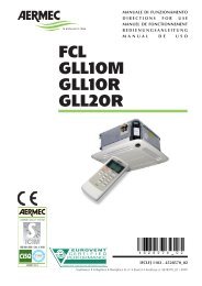
IMPOSTAZIONI DIP-SWITCH<br />
Da eseguire in fase di installazione solo da personale specializzato.<br />
Agendo sui Dip-Switch (figg. 6 e 7) all’interno del termostato<br />
otterremo le seguenti funzionalità:<br />
(Per un corretto funzionamento i Dip 1 e 2 devono avere la<br />
stessa impostazione).<br />
Dip 1 (Default OFF )<br />
Valvola di intercettazione:<br />
-se assente impostare OFF<br />
-se presente impostare ON<br />
Dip 2 (Default OFF )<br />
Posizione della sonda temperatura acqua:<br />
-con sonda a valle della valvola o valvola 2 vie impostare OFF,<br />
-con sonda a monte della valvola o valvola 3 vie impostare ON<br />
-la combinazione Dip.1 ON con Dip.2 OFF è sconsigliata, può<br />
trovare applicazione solo in caso di installazione su impianti<br />
che utilizzano solo 2 vie preesistenti.<br />
Dip 3 (Default OFF)<br />
Gestione valvola:<br />
-per Valvola Ottimizzata impostare OFF<br />
-per Valvola Normale impostare ON<br />
Dip 4 (Default OFF)<br />
Correzione Sonda a Caldo per compensare il surriscaldamento<br />
della strutttura metallica:<br />
-correzzione ottimizzata impostare OFF<br />
-correzzione fissa impostare ON<br />
Dip 5 (Default OFF)<br />
Abilitazione modo Caldo in base alla temperatura dell’acqua:<br />
-per modo Caldo Normale (39°C) impostare OFF<br />
-per modo Caldo Ridotto (35°C) impostare ON<br />
Dip 6 (Default OFF)<br />
Abilitazione modo Freddo in base alla temperatura dell’acqua:<br />
-per modo Freddo Normale (17°C) impostare OFF<br />
-per modo Freddo Ridotto (22°C) impostare ON<br />
OFF<br />
ON<br />
Fig. 6<br />
10<br />
DIPSWITCH CONFIGURATION<br />
Configuration of dipswitches must only be carried out by qualified<br />
personnel during unit installation.<br />
Adjust the dipswitches (figures 6 + 7) inside the thermostat for<br />
the following functions:<br />
(Dip 1 and 2 must have the same configuration for a correct<br />
functioning).<br />
Dipswitch 1 (Default OFF )<br />
Shut-off valve:<br />
- if not fitted, set to OFF<br />
- if fitted, set to ON<br />
Dipswitch 2 (Default OFF )<br />
Water temperature probe:<br />
- if probe is below valve or 2-way valve is fitted, set to OFF<br />
- if probe is above valve or 3-way valve is fitted, set to ON<br />
Combination of Dip.1 ON with Dip.2 OFF is not recommended<br />
(used only for installation on two units using only pre-existing<br />
2-way valves).<br />
Dipswitch 3 (Default OFF)<br />
Valve control:<br />
- for Optimised valve, set to OFF<br />
- for Normal valve, set to ON<br />
Dipswitch 4 (Default OFF)<br />
Probe (Heating) correction to compensate overheating of<br />
metal structure:<br />
- for optimised correction, set to OFF<br />
- for fixed correction, set to ON<br />
Dipswitch 5 (Default OFF)<br />
Enable Heating mode according to water temperature:<br />
- for Normal Heating mode (39°C), set to OFF<br />
- for Reduced Heating (35°C), set to ON<br />
Dipswitch 6 (Default OFF)<br />
Enable Cooling mode according to water temperature:<br />
- for Normal Cooling (17°C), set to OFF<br />
- for Reduced Cooling (22°C), set to ON
CONFIGURAZIONE FCX-ACT FCX-ACT SETTING CONFIGURATION FCX-ACT KONFIGURATION FCX-ACT<br />
OFF<br />
ON<br />
*<br />
*<br />
Valvola di intercettazione assente • No shut off valve<br />
Vanne d'interception absenté • Keine Absperrventil<br />
Sonda Acqua sullo scambiatore o valvola a 2 vie • Temperature water on exchanger or on 2-way valve<br />
Sonde eau sur l'échangeur ou vanne à 2 voies • Wasserfühler auf Wärmetauscher oder 2-Wege Ventil<br />
*<br />
*<br />
Gestione valvola ottimizzata • Optimised valve control<br />
Gestion vanne optimisée • Optimaler Ventilkontrolle<br />
*<br />
Correzione Sonda ottimizzata • Optimised probe correction<br />
Correction sonde optimisée • Normaler Heizbetrieb<br />
*<br />
1 2 3 4 5 6<br />
Abilitazione Caldo Normale • Enable standard set heating<br />
Validation chaleur normale • Normaler Heizbetrieb<br />
*<br />
Abilitazione Freddo Normale • Enable standard set cooling<br />
Validation rafraîchissement normal • Normaler Kühlbetrieb<br />
Abilitazione Freddo Ridotto • Enable reduced set cooling<br />
Validation rafraîchissement réduit • Reduzierter Kèhlbetrieb<br />
Abilitazione Caldo Ridotto • Enable reduced set heating<br />
Validation chaleur réduit • Reduzierter Heizbetrieb<br />
Correzione Sonda fissa • Standard probe control<br />
Correction sonde fixe • Standardkorrektur des Fühlers<br />
Gestione valvola normale • Standard valve control<br />
Gestion vanne normale • Standardkorrektur des Fühlers<br />
Sonda Acqua a Monte della valvola o valvola a 3 vie • Temperature probe before valve or 3-Way valve<br />
Sonde eau en a mont de la vanne ou vanne à 3 voies • Wasserfühler vor Ventil oder 3-Wege Ventil<br />
Valvola di intercettazione presente • Shut off valve is present<br />
Présence de la vanne d'interception • Absperrventil anwesend<br />
= Impostazioni di fabbrica • Factory settings • Configurations de l'usine • Werkseinstellung<br />
REGLAGES DES COMMUTATEURS DIP<br />
A faire exécuter au cours de l'installation uniquement par du<br />
personnel spécialisé.<br />
En agissant sur les commutateurs dip (Fig. 6 et 7) situés à<br />
l'intérieur du thermostat, on obtient les fonctions suivantes:<br />
(Pour un fonctionnement correct Dip 1 et 2 doivent être dans<br />
la même position).<br />
Dip 1 (Default OFF )<br />
Vanne d'arrêt:<br />
-si absente, régler OFF<br />
-si présente, régler ON<br />
Dip 2 (Default OFF )<br />
Position de la sonde de température de l'eau:<br />
- avec une sonde en aval de la vanne ou avec une vanne à 2<br />
voies, régler OFF,<br />
- avec une sonde en amont de la vanne ou avec une vanne à 3<br />
voies, régler ON;<br />
- la combinaison Dip.1 ON avec Dip.2 OFF est déconseillée;<br />
elle ne peut être appliquée qu'en cas d'installation sur les<br />
systèmes utilisant uniquement deux voies préexistantes.<br />
Dip 3 (Default OFF)<br />
Gestion de la vanne:<br />
- pour la Vanne Optimisée, régler OFF<br />
- pour la Vanne Normale, régler ON<br />
Dip 4 (Default OFF)<br />
Correction de la sonde en Chauffage pour compenser la surchauffe<br />
de la structure métallique :<br />
- correction optimisée, régler OFF<br />
- correction fixe, régler ON<br />
Dip 5 (Default OFF)<br />
Validation mode Chauffage en fonction de la température de<br />
l'eau:<br />
- pour mode Chauffage Normal (39°C), régler OFF<br />
- pour mode Chauffage Réduit (35°C), régler ON<br />
Dip 6 (Default OFF)<br />
Validation mode Rafraîchissement en fonction de la température<br />
de l'eau :<br />
- pour mode Rafraîchissement Normal (17°C), régler OFF<br />
- pour mode Rafraîchissement Réduit (22°C), régler ON<br />
11<br />
Fig. 7<br />
EINSTELLUNG DES DIP-SCHALTERS<br />
Diese Einstellung muss bei der Installation von einer Fachkraft<br />
vorgenommen werden.<br />
Mit den DIP-Schaltern (Abb. 6 u. 7) im Temperaturregler werden<br />
folgende Funktionen aktiviert:<br />
(Für einen normalen Betrieb sollen Dip 1 - 2 dieselbe<br />
Einstellung haben).<br />
Dip-Schalter 1 (Voreinstellung OFF )<br />
Absperrventil:<br />
- falls nicht montiert, auf OFF schalten<br />
- falls montiert, auf ON schalten<br />
Dip-Schalter 2 (Voreinstellung OFF )<br />
Position des Wassertemperaturfühlers:<br />
- Temperaturfühler hinter dem Ventil oder Zweiwegeventil -<br />
auf OFF schalten,<br />
- Temperaturfühler vor dem Ventil oder Dreiwegeventil - auf<br />
ON schalten.<br />
- Die Kombination Dip-Schalter 1 auf ON und Dip-Schalter 2 auf<br />
OFF ist nicht empfehlenswert. Sie wird nur bei Installationen in<br />
bestehende Anlagen mit nur 2 Leitungen verwendet.<br />
Dip-Schalter 3 (Voreinstellung OFF)<br />
Ventilsteuerung:<br />
- Ventil mit optimiertem Betrieb: auf OFF schalten<br />
- Ventil mit Normalbetrieb: auf ON schalten<br />
Dip-Schalter 4 (Voreinstellung OFF)<br />
Bei Heizbetrieb Korrektur des Temperaturfühlers zur<br />
Kompensation der Wärmeausdehnung des Metallgehäuses:<br />
- Optimierte Korrektur: auf OFF schalten<br />
- Korrektur mit Festwert: auf ON schalten<br />
Dip-Schalter 5 (Voreinstellung OFF)<br />
Freigabe des Heizbetriebs in Funktion der Wassertemperatur:<br />
- für normalen Heizbetrieb (39 °C) auf OFF schalten<br />
- für reduzierten Heizbetrieb (35 °C) auf ON schalten<br />
Dip-Schalter 6 (Voreinstellung OFF)<br />
Freigabe des Kühlbetriebs in Funktion der Wassertemperatur:<br />
- für normalen Kühlbetrieb (17 °C) auf OFF schalten<br />
- für reduzierten Kühlbetrieb (22 °C) auf ON schalten.<br />
FFFCXX - ACT
FCCX - ACTTT<br />
AUTOTEST<br />
É necessario eseguire la funzione Autotest per accertare il<br />
funzionamento del ventilatore, delle valvole e della resistenza.<br />
La sequenza di Autotest è la seguente:<br />
1) Selettore (B) in posizione centrale.<br />
2) Selettore (A) in posizione OFF.<br />
3) Agendo sul selettore (A), eseguire velocemente la sequenza:<br />
AUTO → OFF → V1 → OFF → V2 → OFF → V3 → OFF.<br />
A questo punto si entra in modo AUTOTEST, il LED FUCSIA<br />
lampeggia.<br />
4) Con il selettore (A) in posizione AUTO si accende la valvola.<br />
Il led giallo (D) esegue cicli di 1 lampeggio.<br />
5) Con il selettore (A) in posizione V1 si accende la velocità<br />
minima V1. Il led giallo (D) esegue cicli di 2 lampeggi.<br />
6) Con il selettore (A) in posizione V2 si accende la velocità<br />
media V3. Il led giallo (D) esegue cicli di 3 lampeggi.<br />
7) Con il selettore (A) in posizione V3 si accende<br />
la velocità massima V3. Il led giallo (D) esegue<br />
cicli di 4 lampeggi .<br />
La modalità Autotest si interrompe automaticamente<br />
dopo un minuto.<br />
AUTOTEST<br />
Il est nécessaire d'exécuter la fonction Autotest<br />
pour contrôler le fonctionnement du ventilateur,<br />
des vannes et de la résistance.<br />
La séquence de l'Autotest est la suivante:<br />
1) Sélecteur (B) sur la position centrale.<br />
2) Sélecteur (A) sur la position OFF.<br />
3) A l'aide du sélecteur (A), exécuter rapidement<br />
la séquence:<br />
AUTO → OFF → V1 → OFF → V2 → OFF → V3 → OFF.<br />
A ce moment donné, on accède au mode AUTOTEST, la LED<br />
FUCHSIA clignote.<br />
4) Le sélecteur (A) étant sur la position AUTO, la vanne s'allume.<br />
La led jaune (D) exécute des cycles de 1 clignotement.<br />
5) Le sélecteur (A) étant sur la position V1, la vitesse minimale<br />
V1 est lancée. La led jaune (D) exécute des cycles de 2 clignotements.<br />
6) Le sélecteur (A) étant sur la position V2, la vitesse moyenne<br />
V3 est lancée. La led jaune (D) exécute des cycles de 3 clignotements.<br />
7) Le sélecteur (A) étant sur la position V3, la vitesse maximale<br />
V3 est lancée. La led jaune (D) exécute des cycles de 4 clignotements.<br />
La fonction Autotest s'interrompt automatiquement au bout<br />
d'une minute.<br />
12<br />
AUTOTEST FUNCTION<br />
This function is designed to check the operation of the <strong>fan</strong>,<br />
valves and heaters.<br />
To run the Autotest function, proceed as follows:<br />
1) Selector switch B in central position.<br />
2) Selector switch A in OFF position.<br />
3) Adjust the selector switch A rapidly to obtain the following<br />
sequence:<br />
AUTO → OFF → V1 → OFF → V2 → OFF → V3 → OFF.<br />
At this stage the unit sets to AUTOTEST mode (PINK LED flashing).<br />
4) With the selector switch A in the AUTO position, the valve<br />
is activated. Yellow LED (D) runs 1-flash cycles.<br />
5) With the selector switch A in the V1 position, minimum<br />
speed V1 is activated. Yellow LED (D) runs 2-flash cycles.<br />
6) With the selector switch A in the V2 position, the medium<br />
speed V2 is activated. Yellow LED (D) runs 3flash<br />
cycles.<br />
7) With the selector switch A in the V3 position,<br />
the maximum speed V3 is activated. Yellow LED<br />
(D) runs 4-flash cycles.<br />
The Autotest function automatically stops after<br />
one minute.<br />
AUTOTEST-FUNKTION<br />
Die Autotest-Funktion muss ausgeführt werden,<br />
um den einwandfreien Betrieb des Gebläses<br />
sowie der Ventile und des Heizelements nachzuweisen.<br />
Der Ablauf der Autotest-Funktion ist wie folgt:<br />
1) Wahlschalter (B) in Mittelstellung.<br />
2) Wahlschalter (A) in Stellung OFF.<br />
3) Mit Wahlschalter (A) rasch die folgende Sequenz schalten:<br />
AUTO → OFF → V1 → OFF → V2 → OFF → V3 → OFF.<br />
Hiermit wird der AUTOTEST-Modus eingeschaltet, die FUCH-<br />
SIAFARBENE LED blinkt.<br />
4) Mit Wahlschalter (A) in Stellung AUTO das Ventil einschalten.<br />
Die gelbe Led (D) blinkt zyklisch jeweils einmal.<br />
5) Mit Wahlschalter (A) in Stellung V1 die Mindestdrehzahl V1<br />
einschalten. Die gelbe Led (D) blinkt zyklisch jeweils zweimal.<br />
6) Mit Wahlschalter (A) in Stellung V2 die mittlere<br />
Drehzahlstufe V2 einschalten. Die gelbe Led (D) blinkt zyklisch<br />
jeweils dreimal.<br />
7) Mit Wahlschalter (A) in Stellung V3 die Höchstdrehzahl V3<br />
einschalten. Die gelbe Led (D) blinkt zyklisch jeweils viermal.<br />
Der Autotest-Modus bricht automatisch nach einer Minute ab.<br />
Fig. 8
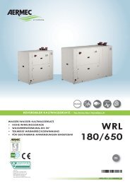
USI IMPROPRI IMPROPER USES USAGES IMPROPRES UNSACHGEMÄßER GEBRAUCH<br />
MANUTENZIONE<br />
Il ventilconvettore AERMEC è<br />
costruito con tecnologie moderne<br />
che ne assicurano l’efficenza<br />
ed il funzionamento nel<br />
tempo.<br />
Pertanto l’unica manutenzione<br />
che necessita è la pulizia<br />
del filtro dell’aria per avere un<br />
funzionamento ottimale del<br />
ventilconvettore e, soprattutto,<br />
per ottenere una corretta filtrazione<br />
dell’aria.<br />
È sufficiente pulire<br />
periodicamente il filtro,<br />
estraendolo dalla sua sede.<br />
Il lavaggio può essere effettuato<br />
con acqua corrente e normali<br />
detergenti, occorre<br />
asciugare bene il filtro prima<br />
di riposizionarlo nella sua<br />
sede.<br />
Una pulizia quindicinale può<br />
essere sufficiente per ambienti<br />
non eccessivamente polverosi.<br />
PER PULIRE L’UNITÀ:<br />
Non indirizzare getti d’acqua<br />
sull’unità. Può causare scosse<br />
elettriche o danneggiare l’unità.<br />
Non usare acqua calda, sostanze<br />
abrasive o solventi; per pulire<br />
l’unità usare un panno soffice.<br />
MAINTENANCE<br />
The AERMEC <strong>fan</strong><strong>coil</strong> is constructed<br />
with state of the art technology<br />
that ensures long-term efficiency<br />
and operation.<br />
The only maintenance required<br />
is to clean the air filters,<br />
which optimises the <strong>fan</strong><strong>coil</strong>s<br />
operation and, above all,<br />
achieves an effective filtration<br />
of the air.<br />
It is quite sufficient to periodically<br />
wash the filter, by simply<br />
sliding it out of its housing.<br />
The filter can be washed with<br />
tap water and usual detergents.<br />
Make sure it is dry before<br />
replacing in its housing.<br />
Cleaning every fifteen days is<br />
enough for rooms which are<br />
not excessively dusty.<br />
TO CLEAN THE UNIT:<br />
Do not splash water on the unit.<br />
It could result in electrical shock<br />
or damage to the product.<br />
Do not use hot water, abrasive<br />
powders or strong solvents; to<br />
clean the unit use a soft cloth.<br />
ENTRETIEN<br />
Le convecteur soufflant<br />
AERMEC est construit avec<br />
des technologies modernes<br />
qui garantissent son efficacité<br />
et son fonctionnement pour<br />
longtemps.<br />
C'est pourquoi, le seul entretien<br />
qu’il requiert est le nettoyage<br />
du filtre à air pour assurer<br />
un fonctionnement optimal<br />
du convecteur soufflant<br />
et surtout pour obtenir un filtrage<br />
parfait de l’air.<br />
Pour se faire, il suffit de nettoyer<br />
périodiquement le filtre en<br />
l’enlevant de son emplacement.<br />
Le lavage peut se faire avec<br />
de l’eau et des détergents habituels.<br />
Bien essuyer le filtre avant de<br />
le remettre dans son emplacement.<br />
Un nettoyage par quinzaine<br />
est suffisant pour des locaux<br />
qui ne sont pas excessivement<br />
poussiéreux.<br />
POUR NETTOYER L’UNITÉ:<br />
Ne pas diriger de jet d’eau en<br />
direction de l’unité. Cela peut<br />
causer des chocs électriques<br />
ou endommager l’unité.<br />
Ne pas utiliser d’eau chaude,<br />
de substances abrasives ou de<br />
solvants; pour nettoyer l’unité,<br />
utiliser un chiffon doux.<br />
GUERRA E PACE<br />
ASSASSINIO SUL<br />
L'ORIENT EXPRESS<br />
20.000 LEGHE<br />
SOTTO I MARI<br />
13<br />
WARTUNG<br />
Der Gebläsekonvektor AER-<br />
MEC ist nach modernen<br />
Technologien gebaut, die eine<br />
dauerhafte Leistungsfähigkeit<br />
und eine lange Standzeit<br />
gewährleisten.<br />
Für einen optimalen Betrieb<br />
des Gebläsekonvektors ist als<br />
einzige Wartung die regelmäßige<br />
Reinigung des Luftfilters<br />
erforderlich, um eine<br />
ordnungsgemäße Luftfiltration<br />
zu sichern.<br />
Der Filter ist für die Reinigung<br />
auszubauen.<br />
Das Spülen des Filtermaterials<br />
kann mit Leitungswasser<br />
und normalen Reinigungsmitteln<br />
erfolgen.<br />
Der Filter ist vor dem erneuten<br />
Einsatz sorgfältig zu<br />
trocknen.<br />
Eine Reinigung alle zwei<br />
Wochen ist bei nicht übermäßig<br />
staubhaltigen Räumen<br />
ausreichend.<br />
REINIGUNG DES GERÄTES:<br />
Keine Wasserstrahlen auf das<br />
Gerät richten, da Stromschläge<br />
oder Geräteschäden entstehen<br />
könnten. Kein heißes Wasser,<br />
Scheuermittel oder<br />
Lösungsmittel verwenden.<br />
Das Gerät mit einem weichen<br />
Tuch reinigen.<br />
PERICOLO: Togliere tensione prima d’iniziare le operazioni di pulizia del filtro e/o dell’unità.<br />
DANGER: Switch off power supply before cleaning filter and/or unit.<br />
DANGER: Couper la tension avant de commencer les opérations de nettoyage du filtre et/ou de<br />
l'unité.<br />
GEFAHR: Vor der Reinigung des Filters und/oder des Gerätes die Stromversorgung abschalten.
PROBLEMA PROBLEM<br />
PROBLEME PROBLEM<br />
Poca aria in uscita<br />
Feeble air discharge<br />
Il y a peu d’air en sortie<br />
Schwacher Luftstrom am Austritt<br />
Non fa caldo<br />
It does not heat<br />
Pas de chaleur<br />
Keine Heizung<br />
Non fa freddo<br />
It does not cool<br />
Pas de froid<br />
Keine Kühlung<br />
Il ventilatore non gira<br />
The <strong>fan</strong> does not turn<br />
Le ventilateur ne tourne pas<br />
Ventilator Arbeitet nicht<br />
Fenomeni di condensazione<br />
sulla struttura esterna dell’apparecchio.<br />
Condensation on the unit<br />
cabinetCondensation on the<br />
unit cabinet<br />
Phénoménes de condensation<br />
sur la structure externe de<br />
l’appareil.<br />
Kondenswasserbildung am<br />
Gerät.<br />
PROBABILE CAUSA PROBABLE CAUSE<br />
CAUSE PROBABLE MÖGLICHE URSACHE<br />
Errata impostazione della velocità sul pannello comandi<br />
Wrong speed setting on the control panel<br />
Mauvaise préselection de la vitesse sur le panneau de commandes<br />
Falsche Geschwindigkeitseinstellung am Bedienpaneel<br />
Filtro intasato<br />
Blocked filter<br />
Filtre encrassé<br />
Filter verstopft<br />
Ostruzione del flusso d’aria (entrata e/o uscita)<br />
Obstruction of the air flow (inlet and/or outlet)<br />
Obstruction du flux d’air (entrée/sortie)<br />
Luftstrom behindert (Eintritt bzw. Austritt)<br />
Mancanza di acqua calda<br />
Poor hot water supply<br />
Il n’y a pas d’eau chaude<br />
Kein Warmwasser<br />
Impostazione errata del pannello comandi<br />
Wrong setting on control panel<br />
Mauvaise présélection sur le panneau de commandes<br />
Falsche Einstellung am Bedienpaneel<br />
Mancanza di acqua fredda<br />
Poor chilled water supply<br />
Il n’y a pas d’eau froide<br />
Kein Kaltwasser<br />
Impostazione errata del pannello comandi<br />
Wrong setting on control panel<br />
Mauvaise présélection sur le panneau de commandes<br />
Falsche Einstellung am Bedienpaneel<br />
Mancanza di corrente<br />
No current<br />
l n’y a pas de courant<br />
Kein Strom<br />
È intervenuta, se presente, la sonda, perchè l’acqua è scesa<br />
sotto i 35 °C (nel funzionamento invernale)<br />
If present, the water sensor has tripped because the temperature<br />
has dropped below 35 °C (in winter mode)<br />
Si elle est présente, la sonde de température de l’eau s’est mise<br />
en route car celle-ci est en dessous de 35 °C (fonctionnement<br />
hivernal)<br />
Es hat, sofern vorhanden, der Warmwassersensor angesprochen,<br />
da die Wassertemperatur unter 35 °C gesunken ist (im<br />
Winterbetrieb)<br />
Sono state raggiunte le condizioni limite di temperatura e umidità<br />
descritte nel Manuale Tecnico (Limiti di funzionamento).<br />
The limit conditions of temperature and humidity indicated in<br />
the Technical booklets (Operating limits) have been reached.<br />
On a atteint les conditions limite de température et de humidité<br />
indiquées dans le Manuel Tecnique (Limites de fonctionnement).<br />
Erreichen der maximalen Temperatur- und Feuchtigkeitswerte<br />
(Betriebsgrenzen) anhand der technischen Anleitung.<br />
Per anomalie non contemplate, interpellare tempestivamente il Servizio Assistenza<br />
For anomalies don’t hesitate, contact the aftersales service immediately<br />
Pour toute anomalie non répertoriée, consulter le service après-vente<br />
Sich bei hier nicht aufgeführten Störungen umgehend an den Kundendienst wenden<br />
14<br />
SOLUZIONE REMEDY<br />
SOLUTION ABHILFE<br />
Scegliere la velocità corretta sul pannello<br />
comandi<br />
Select the speed on the control panel<br />
Choisir la vitesse sur la panneau de commandes<br />
Die Geschwindigkeit am Bedienpaneel wählen<br />
Pulire il filtro<br />
Clean the filter<br />
Nettoyer le filtre<br />
Filter reinigen<br />
Rimuovere l’ostruzione<br />
Remove the obstruction<br />
Enlever l’objet faisant obstruction<br />
Verstopfung beseitigen<br />
Controllare la caldaia<br />
Control the boiler<br />
Verifier la chaudière<br />
Kaltwasserseitigen Wärmeaustauscher kontrollieren<br />
Impostare il pannello comandi<br />
See control panel settings<br />
Présélectionner au panneau de commandes<br />
Richtige Einstellung am Bedienpaneel vornehmen<br />
Controllare il refrigeratore<br />
Control the chiller<br />
Vérifier le réfrigerateur<br />
Kaltwasserseitigen Wärmeaustauscher kontrollieren<br />
Impostare il pannello comandi<br />
See control panel settings<br />
Présélectionner au panneau de commandes<br />
Richtige Einstellung am Bedienpaneel vornehmen<br />
Controllare la presenza di tensione elettrica<br />
Control the power supply<br />
Contrôler l’alimentation électrique<br />
Kontrollieren, ob Spannung anliegt<br />
Controllare la caldaia<br />
Control the boiler<br />
Vérifier la chaudière<br />
Kaltwasserseitigen Wärmeaustauscher kontrollieren<br />
Inalzare la temperatura dell’acqua oltre i<br />
limiti minimi descritti nel Manuale Tecnico.<br />
Increase the water temperature beyond the<br />
minimum limits indicated in the technical<br />
booklet.<br />
Elever la température de l’eau audelà des<br />
limites minimales indiquées dans le Manuel<br />
Tecnique.<br />
Erhöhung der Wassertemperatur oberhalb der<br />
in technischen Anleitung beschriebenen<br />
Minimalgrenze.
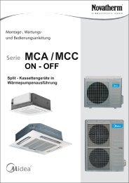
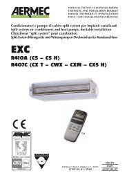
Minima temperatura media dell’acqua<br />
Per evitare fenomeni di condensazione sulla struttura esterna<br />
dell’apparecchio con ventilatore in funzione, la temperatura<br />
media dell’acqua non deve essere inferiore ai limiti riportati<br />
nella tabella sottostante, che dipendono dalle condizioni<br />
termo-igrometriche dell’aria ambiente.<br />
I suddetti limiti si riferiscono al funzionamento con ventilatore<br />
in moto alla minima velocità .<br />
In caso di prolungata situazione con ventilatore spento e passaggio<br />
di acqua fredda in batteria, è possibile la formazione di<br />
condensa all’esterno dell’apparecchio.<br />
Température moyenne minimale de l'eau<br />
Pour éviter des phénomènes de condensation sur la structure<br />
extérieure de l'appareil, la température moyenne de l'eau ne<br />
doit pas être inférieure aux limites indiquées dans le tableau<br />
ci-dessous, qui dépendent des conditions thermo-hygrométriques<br />
de l'air ambiant.<br />
Les limites précitées se rapportent au fonctionnement à la<br />
vitesse minimale.<br />
En cas de longue période avec ventilateur éteint et passage<br />
d'eau froide dans la batterie la formation de condensas à<br />
l'extérieur de l'appareil est possible.<br />
Average minimum water temperature<br />
To prevent the formation of condensate on the exterior of the<br />
unit, the average water temperature should not drop below the<br />
limits given in the table (see below); the limits are given by the<br />
humidity conditions and temperature of ambient air.<br />
The above limits refer to units operating at minimum speed.<br />
During periods with <strong>fan</strong>s switched off and water is flowing in<br />
the heat exchanger, the condensate might collect on the exterior<br />
of the unit<br />
Durchschnittliche Mindest-Wassertemperatur<br />
Um Kondensationserscheinungen auf der Außenseite der Einheit<br />
zu verhindern, darf die durchschnittliche Wassertemperatur nicht<br />
unter die Grenzwerte in untenstehender Tabelle sinken.<br />
Die Grenzwerte hängen von den thermohygrometrischen<br />
Bedienungen der Raumluft ab und betreffen die kritischste<br />
Anwendung den Betrieb bei Mindestdrehzahl.<br />
Beim stehenden Ventilator und Kaltwasserdurchfluß in den<br />
Wärmetauscher ist eine Kondesatbildung am Gerät möglich.<br />
MINIMA TEMPERATURA MEDIA ACQUA Temperatura a bulbo secco dell’aria ambiente °C<br />
MINIMUM AVERAGE WATER TEMPERATURE Dry bulb temperature °C<br />
TEMPÉRATURE MINIMUM MOYENNE DE L’EAU Température bulbe sèche °C<br />
MINIMALE MITTLERE WASSERTEMPERATUR Temperatur T.K. °C<br />
21 23 25 27 29 31<br />
Temperatura a bulbo umido 15 3 3 3 3 3 3<br />
dell’aria ambiente °C 17 3 3 3 3 3 3<br />
Wet bulb temperature °C 19 3 3 3 3 3 3<br />
Température bulbe humide °C 21 6 5 4 3 3 3<br />
Temperatur F.K. °C 23 - 8 7 6 5 5<br />
15
GARANZIA DI 3 ANNI<br />
La garanzia è valida solo se l’apparecchio è venduto ed installato sul territorio italiano. Il periodo decorre dalla data di acquisto<br />
comprovata da un documento che abbia validità fiscale (fattura o ricevuta) e che riporti la sigla commerciale dell’apparecchio.<br />
Il documento dovrà essere esibito, al momento dell’intervento, al tecnico del Servizio Assistenza Aermec di zona.<br />
Il diritto alla garanzia decade in caso di:<br />
- interventi di riparazione effettuati sull’apparecchiatura da tecnici non autorizzati;<br />
- guasti conseguenti ad azioni volontarie o accidentali che non derivino da difetti originari dei materiali di fabbricazione.<br />
L’Aermec Spa effettuerà la riparazione o la sostituzione gratuita, a sua scelta, delle parti di apparecchiatura che dovessero<br />
presentare difetti dei materiali o di fabbricazione tali da impedire il normale funzionamento.<br />
Gli eventuali interventi di riparazione o sostituzione di parti dell’apparecchio, non modificano la data di decorrenza e la<br />
durata del periodo di garanzia.<br />
Le parti difettose sostituite resteranno di proprietà dell’Aermec Spa.<br />
Non è prevista in alcun caso la sostituzione dell’apparecchio. La garanzia non copre le parti dell’apparecchio che risultassero<br />
difettose a causa del mancato rispetto delle istruzioni d’uso, di un’errata installazione o manutenzione, di danneggiamenti<br />
dovuti al trasporto, di difetti dell’impianto (es: scarichi di condensa non efficienti).<br />
Non sono coperte, infine, le normali operazioni di manutenzione periodica (es: la pulizia dei filtri d’aria) e la sostituzione<br />
delle parti di normale consumo (es: ifiltri d’aria).<br />
Le Agenzie di Vendita Aermec ed i Servizi di Assistenza Tecnica Aermec della vostra provincia sono negli Elenchi Telefonici<br />
dei capoluoghi di provincia - vedi “Aermec” - e nelle Pagine Gialle alla voce “Condizionatori d’aria - Commercio”.<br />
I dati tecnici riportati nella presente documentazione non sono impegnativi.<br />
L’Aermec S.p.A. si riserva la facoltà di apportare in qualsiasi momento tutte le<br />
modifiche ritenute necessarie per il miglioramento del prodotto.<br />
Technical data shown in this booklet are not binding.<br />
Aermec S.p.A. shall have the right to introduce at any time whatever modifications<br />
deemed necessary to the improvement of the product.<br />
AERMEC S.p.A.<br />
I-37040 Bevilacqua (VR) - Italia<br />
Via Roma, 44 - Tel. (+39) 0442 633111<br />
Telefax (+39) 0442 93566 - 0442 93730<br />
www.aermec.com<br />
Les données mentionnées dans ce manuel ne constituent aucun engagement de<br />
notre part.<br />
Aermec S.p.A. se réserve le droit de modifier à tous moments les données considérées<br />
nécessaires à l’amelioration du produit.<br />
Im Sinne des technischen Fortsschrittes behält sich Aermec S.p.A. vor, in der<br />
Produktion Änderungen und Verbesserungen ohne Ankündigung durchzuführen.<br />
carta riciclata<br />
recycled paper<br />
papier recyclé<br />
recycled Papier