GUIDE TCI LED DRIVERS 2016-17
ATON 30/250-700 DALI Direct current dimmable electronic drivers with DIP-SWITCH Alimentatori elettronici regolabili in corrente continua con DIP-SWITCH Made in Europe professional led applications SELV RIPPLE FREE 3.2 ATON 30/250-700 DALI ATON 30/250-700 DALI BI Dimmable multipower LED drivers Alimentatori LED multipotenza regolabili Rated Voltage Tensione Nominale 220 ÷ 240 V Frequency Frequenza 50...60 Hz AC Operation range Tensione di utilizzo AC 198 ÷ 264 V DC Operation range Tensione di utilizzo DC 176 ÷ 264 V (NO PUSH mode functions) Power Potenza 0 ÷ 30 W Maximum current output ripple Max. ondulazione della corrente uscita ≤ 3% (1) Reference Norms Norme di riferimento: EN 50172 (VDE 0108) EN 55015 EN 61000-3-2 EN 61000-3-3 EN 61347-1 EN 61347-2-13 EN 61547 EN 62384 EN 62386-101 EN 62386-102 EN 62386-207 VDE 0710-T14 Article Articolo ATON 30/250-700 DALI ATON 30/250-700 DALI BI Code Codice 127370 127372 P out W V out DC I out DC (1) Referred to V in = 230 V, 100% load - Riferito a V in = 230 V, carico 100% (2) Pout > 12 W Features • Multipower driver supplied with dip-switch for the selection of the output current. • IP20 independent driver, for indoor use (ATON). • Class I protection against electric shock for direct or indirect contact (ATON). • Driver for built-in use (ATON BI). • It can be used for lighting equipment in protection class I (ATON BI). • Active Power Factor Corrector. • Current regulation ±5 % including temperature variations. • Input and output terminal blocks on the opposite sides (wire cross-section up to 1,5 mm 2 / AWG15). • Clamping screws on primary and secondary circuits for cables with diameter: min. 3 mm - max. 8 mm (ATON). • Driver can be secured with slot for screws. • Protections: - against overheating and short circuits; - against mains voltage spikes; - against overloads. • Thermal protection = C.5.a. V out max. ta °C tc °C l Power Factor h max. Efficiency (1) 13 20...54 (3) 250 mA cost. 59 -25...+50 85 0,95 (2) >88 15 15...54 (3) 280 mA cost. 16,5 10...54 (3) 310 mA cost. 18 2...54 (3) 340 mA cost. 19,5 2...54 (3) 370 mA cost. 21 2...54 (3) 400 mA cost. 22,5 2...54 (3) 430 mA cost. 24 2...54 (3) 460 mA cost. 26 2...54 (3) 490 mA cost. 27,5 2...50 520 mA cost. 29 2...50 550 mA cost. 30 2...50 580 mA cost. 30 2...50 610 mA cost. 30 2...46 640 mA cost. 30 2...45 670 mA cost. 30 2...43 700 mA cost. Caratteristiche • Alimentatore multipotenza fornito di dip-switch per la selezione della corrente in uscita. • Alimentatore indipendente IP20, per uso interno (ATON). • Protetto in classe I contro le scosse elettriche per contatti diretti e indiretti (ATON). • Alimentatore da incorporare (ATON BI). • Utilizzabile per apparecchi di illuminazione in classe di protezione I (ATON BI). • PFC attivo. • Corrente regolata ±5 % incluse variazioni di temperatura. • Morsetti di entrata e uscita contrapposti (sezione cavo fino a 1,5 mm 2 / AWG15). • Serracavo su primario e secondario per cavi di diametro: min. 3 mm - max. 8 mm (ATON). • Fissaggio dell’alimentatore tramite asole per viti. • Protezioni: - termica e cortocircuito; - contro le extra-tensioni di rete; - contro i sovraccarichi. • Protezione termica = C.5.a. 180 www.tci.it TCI professional LED applications
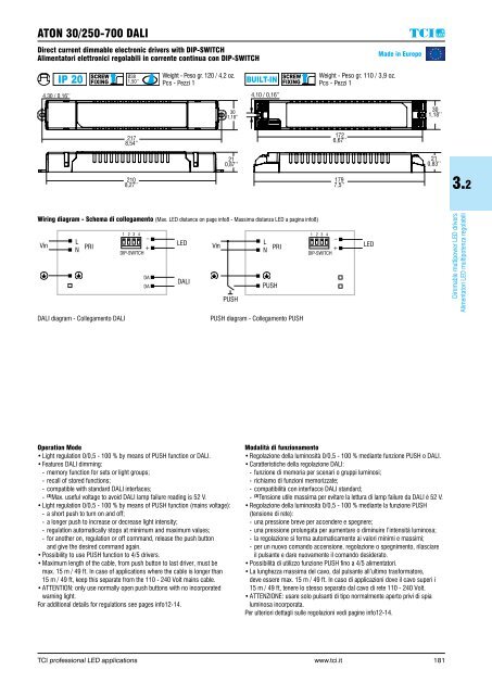
ATON 30/250-700 DALI Direct current dimmable electronic drivers with DIP-SWITCH Alimentatori elettronici regolabili in corrente continua con DIP-SWITCH Made in Europe professional led applications 4,30 / 0,16’’ Ø38 1,50’’ Weight - Peso gr. 120 / 4,2 oz. Pcs - Pezzi 1 4,10 / 0,16’’ Weight - Peso gr. 110 / 3,9 oz. Pcs - Pezzi 1 30 1,18’’ 30 1,18’’ 217 8,54’’ 172 6,67’’ 21 0,87’’ 21 0,83’’ 210 8,27’’ 179 7,5’’ 3.2 Wiring diagram - Schema di collegamento (Max. LED distance on page info8 - Massima distanza LED a pagina info8) Vin L N PRI 1 2 3 4 _ + DIP-SWITCH DA DA LED DALI Vin PUSH 1 2 3 4 _ L N PRI + DIP-SWITCH PUSH LED Dimmable multipower LED drivers Alimentatori LED multipotenza regolabili DALI diagram - Collegamento DALI PUSH diagram - Collegamento PUSH Operation Mode • Light regulation 0/0,5 - 100 % by means of PUSH function or DALI. • Features DALI dimming: - memory function for sets or light groups; - recall of stored functions; - compatible with standard DALI interfaces; - (3) Max. useful voltage to avoid DALI lamp failure reading is 52 V. • Light regulation 0/0,5 - 100 % by means of PUSH function (mains voltage): - a short push to turn on and off; - a longer push to increase or decrease light intensity; - regulation automatically stops at minimum and maximum values; - for another on, regulation or off command, release the push button and give the desired command again. • Possibility to use PUSH function to 4/5 drivers. • Maximum length of the cable, from push button to last driver, must be max. 15 m / 49 ft. In case of applications where the cable is longer than 15 m / 49 ft, keep this separate from the 110 - 240 Volt mains cable. • ATTENTION: only use normally open push buttons with no incorporated warning light. For additional details for regulations see pages info12-14. Modalità di funzionamento • Regolazione della luminosità 0/0,5 - 100 % mediante funzione PUSH o DALI. • Caratteristiche della regolazione DALI: - funzione di memoria per scenari o gruppi luminosi; - richiamo di funzioni memorizzate; - compatibilità con interfacce DALI standard; - (3) Tensione utile massima per evitare la lettura di lamp failure da DALI è 52 V. • Regolazione della luminosità 0/0,5 - 100 % mediante la funzione PUSH (tensione di rete): - una pressione breve per accendere e spegnere; - una pressione prolungata per aumentare o diminuire l’intensità luminosa; - la regolazione si ferma automaticamente ai valori minimi e massimi; - per un nuovo comando accensione, regolazione o spegnimento, rilasciare il pulsante e dare nuovamente il comando desiderato. • Possibilità di utilizzo funzione PUSH fino a 4/5 alimentatori. • La lunghezza massima del cavo, dal pulsante all’ultimo trasformatore, deve essere max. 15 m / 49 ft. In caso di applicazioni dove il cavo superi i 15 m / 49 ft, tenere lo stesso separato dal cavo di rete 110 - 240 Volt. • ATTENZIONE: usare solo pulsanti di tipo normalmente aperto privi di spia luminosa incorporata. Per ulteriori dettagli sulle regolazioni vedi pagine info12-14. TCI professional LED applications www.tci.it 181
- Page 164 and 165: WIDESQUARE R - 1...10 V & PUSH Dire
- Page 166 and 167: JOLLY DIN 32 Direct current dimmabl
- Page 168 and 169: MAXI JOLLY SV DALI 40 Direct curren
- Page 170 and 171: MAXI JOLLY US 50 - 1...10 V & PUSH
- Page 172 and 173: MAXI JOLLY US DALI 50 Direct curren
- Page 174 and 175: MAXI JOLLY SV - SELV 60 V - 1...10
- Page 176 and 177: MAXI JOLLY SV DALI - SELV 60 V Dire
- Page 178 and 179: MAXI JOLLY HV 50 - 1...10 V & PUSH
- Page 180 and 181: MAXI JOLLY HV DALI 50 Direct curren
- Page 182 and 183: MAXI JOLLY US TCM 50 - 1...10 V & P
- Page 184 and 185: MAXI JOLLY US DALI TCM 50 Direct cu
- Page 186 and 187: MAXI JOLLY HC 55 - 1...10 V & PUSH
- Page 188 and 189: MAXI JOLLY HC DALI 55 Direct curren
- Page 190 and 191: MAXI JOLLY HC TCM 55 - 1...10 V & P
- Page 192 and 193: MAXI JOLLY HC DALI TCM 55 Direct cu
- Page 194 and 195: MAXI JOLLY H 65 Direct current dimm
- Page 196 and 197: MAXI JOLLY DALI H 65 Direct current
- Page 198 and 199: MAXI JOLLY HTCM 65 Direct current d
- Page 200 and 201: MAXI JOLLY DALI HTCM 65 Direct curr
- Page 202 and 203: MAXI JOLLY DALI CR 50 Direct curren
- Page 204 and 205: DMX VST Direct current dimmable ele
- Page 206 and 207: RV LED professional led application
- Page 208 and 209: SUPERSLIM 1...10 V Direct current d
- Page 210 and 211: SUPERSLIM DALI Direct current dimma
- Page 212 and 213: SUPERFLAT DALI Direct current dimma
- Page 216 and 217: JOLLY SLIM 32 - 1...10 V & PUSH Dir
- Page 218 and 219: JOLLY SLIM HV 32 - 1...10 V & PUSH
- Page 220 and 221: MAXI JOLLY SLIM 60 - 1...10 V & PUS
- Page 222 and 223: MAXI JOLLY SLIM DALI 60 Direct curr
- Page 224 and 225: MAXI JOLLY SLIM HV 60 - 1...10 V &
- Page 226 and 227: MAXI JOLLY SLIM HV DALI 60 Direct c
- Page 228 and 229: MAXI JOLLY SLIM DALI 60 LS - LEDset
- Page 230 and 231: T-LED 80/350 1...10V SLIM Direct cu
- Page 232 and 233: T-LED 80/500 1...10V SLIM Direct cu
- Page 234 and 235: T-LED 80/700 1...10V SLIM Direct cu
- Page 236 and 237: T-LED 80/350 DALI SLIM Direct curre
- Page 238 and 239: T-LED 80/500 DALI SLIM Direct curre
- Page 240 and 241: T-LED 80/700 DALI SLIM Direct curre
- Page 242 and 243: T-LED 90/580 DALI SLIM Direct curre
- Page 244 and 245: T-LED 80/500 DALI SLIM LS - LEDset2
- Page 246 and 247: professional led applications Made
- Page 248 and 249: SIRIO 150/200-700 Direct current di
- Page 250 and 251: SIRIO 150/300-1050 Direct current d
- Page 252 and 253: SIRIO 150/700 ST2 professional led
- Page 254 and 255: SIRIO 100 - 1...10 V & BILEVEL Dire
- Page 256 and 257: SIRIO 120/600-2100 - 1...10 V & BIL
- Page 258 and 259: SIRIO 150/200-700 - 1...10 V & BILE
- Page 260 and 261: SIRIO 150/300-1050 - 1...10 V & BIL
- Page 262 and 263: MAXI JOLLY US FP - FULL PROGRAMMABL
ATON 30/250-700 DALI<br />
Direct current dimmable electronic drivers with DIP-SWITCH<br />
Alimentatori elettronici regolabili in corrente continua con DIP-SWITCH<br />
Made in Europe<br />
professional led applications<br />
4,30 / 0,16’’<br />
Ø38<br />
1,50’’<br />
Weight - Peso gr. 120 / 4,2 oz.<br />
Pcs - Pezzi 1<br />
4,10 / 0,16’’<br />
Weight - Peso gr. 110 / 3,9 oz.<br />
Pcs - Pezzi 1<br />
30<br />
1,18’’<br />
30<br />
1,18’’<br />
2<strong>17</strong><br />
8,54’’<br />
<strong>17</strong>2<br />
6,67’’<br />
21<br />
0,87’’<br />
21<br />
0,83’’<br />
210<br />
8,27’’<br />
<strong>17</strong>9<br />
7,5’’<br />
3.2<br />
Wiring diagram - Schema di collegamento (Max. <strong>LED</strong> distance on page info8 - Massima distanza <strong>LED</strong> a pagina info8)<br />
Vin<br />
L<br />
N<br />
PRI<br />
1 2 3 4<br />
_<br />
+<br />
DIP-SWITCH<br />
DA<br />
DA<br />
<strong>LED</strong><br />
DALI<br />
Vin<br />
PUSH<br />
1 2 3 4 _<br />
L<br />
N PRI +<br />
DIP-SWITCH<br />
PUSH<br />
<strong>LED</strong><br />
Dimmable multipower <strong>LED</strong> drivers<br />
Alimentatori <strong>LED</strong> multipotenza regolabili<br />
DALI diagram - Collegamento DALI<br />
PUSH diagram - Collegamento PUSH<br />
Operation Mode<br />
• Light regulation 0/0,5 - 100 % by means of PUSH function or DALI.<br />
• Features DALI dimming:<br />
- memory function for sets or light groups;<br />
- recall of stored functions;<br />
- compatible with standard DALI interfaces;<br />
- (3) Max. useful voltage to avoid DALI lamp failure reading is 52 V.<br />
• Light regulation 0/0,5 - 100 % by means of PUSH function (mains voltage):<br />
- a short push to turn on and off;<br />
- a longer push to increase or decrease light intensity;<br />
- regulation automatically stops at minimum and maximum values;<br />
- for another on, regulation or off command, release the push button<br />
and give the desired command again.<br />
• Possibility to use PUSH function to 4/5 drivers.<br />
• Maximum length of the cable, from push button to last driver, must be<br />
max. 15 m / 49 ft. In case of applications where the cable is longer than<br />
15 m / 49 ft, keep this separate from the 110 - 240 Volt mains cable.<br />
• ATTENTION: only use normally open push buttons with no incorporated<br />
warning light.<br />
For additional details for regulations see pages info12-14.<br />
Modalità di funzionamento<br />
• Regolazione della luminosità 0/0,5 - 100 % mediante funzione PUSH o DALI.<br />
• Caratteristiche della regolazione DALI:<br />
- funzione di memoria per scenari o gruppi luminosi;<br />
- richiamo di funzioni memorizzate;<br />
- compatibilità con interfacce DALI standard;<br />
- (3) Tensione utile massima per evitare la lettura di lamp failure da DALI è 52 V.<br />
• Regolazione della luminosità 0/0,5 - 100 % mediante la funzione PUSH<br />
(tensione di rete):<br />
- una pressione breve per accendere e spegnere;<br />
- una pressione prolungata per aumentare o diminuire l’intensità luminosa;<br />
- la regolazione si ferma automaticamente ai valori minimi e massimi;<br />
- per un nuovo comando accensione, regolazione o spegnimento, rilasciare<br />
il pulsante e dare nuovamente il comando desiderato.<br />
• Possibilità di utilizzo funzione PUSH fino a 4/5 alimentatori.<br />
• La lunghezza massima del cavo, dal pulsante all’ultimo trasformatore,<br />
deve essere max. 15 m / 49 ft. In caso di applicazioni dove il cavo superi i<br />
15 m / 49 ft, tenere lo stesso separato dal cavo di rete 110 - 240 Volt.<br />
• ATTENZIONE: usare solo pulsanti di tipo normalmente aperto privi di spia<br />
luminosa incorporata.<br />
Per ulteriori dettagli sulle regolazioni vedi pagine info12-14.<br />
<strong>TCI</strong> professional <strong>LED</strong> applications www.tci.it<br />
181


