Tabella delle perdite di carico nelle tubazioni Pipes charge losses ...
Tabella delle perdite di carico nelle tubazioni Pipes charge losses ...
Tabella delle perdite di carico nelle tubazioni Pipes charge losses ...

You also want an ePaper? Increase the reach of your titles
YUMPU automatically turns print PDFs into web optimized ePapers that Google loves.
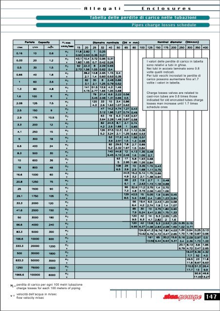
Hj =<br />
per<strong>di</strong>ta <strong>di</strong> <strong>carico</strong> per ogni 100 metri tubazione<br />
<strong>charge</strong> <strong>losses</strong> for each 100 meters of piping<br />
v =<br />
velocità dell’acqua in m/sec<br />
flow velocity m/sec<br />
Allegati Enclosures<br />
<strong>Tabella</strong> <strong>delle</strong> <strong>per<strong>di</strong>te</strong> <strong>di</strong> <strong>carico</strong> <strong>nelle</strong> <strong>tubazioni</strong><br />
<strong>Pipes</strong> <strong>charge</strong> <strong>losses</strong> schedule<br />
I valori <strong>delle</strong> <strong>per<strong>di</strong>te</strong> <strong>di</strong> <strong>carico</strong> in tabella<br />
sono relativi a tubi in ghisa.<br />
Nei tubi in acciaio laminato sono 0.8<br />
volte quelli in<strong>di</strong>cati.<br />
Per tubi vecchi incrostati le <strong>per<strong>di</strong>te</strong> <strong>di</strong><br />
<strong>carico</strong> possono aumentare fino a1.7<br />
voltie i valori in tabella.<br />
Charge <strong>losses</strong> valves are related to<br />
cast-iron tubes are 0.8 times those<br />
in<strong>di</strong>cated for old encrusted tubes <strong>charge</strong><br />
<strong>losses</strong> man increase until 1.7 times<br />
schedule ones<br />
147
148<br />
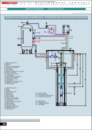
<strong>Tabella</strong> <strong>delle</strong> <strong>per<strong>di</strong>te</strong> <strong>di</strong> <strong>carico</strong> <strong>nelle</strong> curve, saracinesche e valvole<br />
Pressure drop in curves, gates and valves schedule<br />
La per<strong>di</strong>ta <strong>di</strong> <strong>carico</strong> <strong>nelle</strong> curve è soltanto quella dovuta alla contrazione dei<br />
filetti liqui<strong>di</strong> per cambiamento <strong>di</strong> <strong>di</strong>rezione (lo sviluppo <strong>delle</strong> curve deve essere<br />
quin<strong>di</strong> compreso nella lunghezza della tubazione), mentre la per<strong>di</strong>ta <strong>di</strong> <strong>carico</strong><br />
<strong>nelle</strong> valvole a saracinesche è stata determinata in base a prove tecniche.<br />
La per<strong>di</strong>ta <strong>di</strong> <strong>carico</strong> per saracinesche e curve normali è pari a quella <strong>di</strong> 5 metri<br />
<strong>di</strong> tubazione <strong>di</strong>ritta mentre per valvole <strong>di</strong> ritegno a clapet a 15 metri.<br />
I valori in<strong>di</strong>cati si intendodo per tubazione internamente liscia.<br />
In caso <strong>di</strong> tubazione incrostata occorrerà considerare i corrispondenti aumenti.<br />
Allegati Enclosures<br />
The pressure drop in curves is only the one due to the contraction of the<br />
liquid thin thread for <strong>di</strong>rectional change (the development of the curves<br />
must be included in the length of the piping), while the pressure drop in<br />
the valves and gates is been determined on the basis of technical testes.<br />
The pressure drop for gates and normal curves is equal to 5 metres of<br />
straigth piping, while for not return clapet valve is to 15 metres.<br />
The values in<strong>di</strong>cated are intended for piping internally smooth.<br />
In case of overlaid piping, will need to consider the correspon<strong>di</strong>ng increase.
Allegati Enclosures<br />
<strong>Tabella</strong> <strong>di</strong> scelta del generatore elettrico idoneo per l’azionamento del motore<br />
Choosing table of an electric generator suitable for the starting to power motor<br />
149
150<br />
Potenza:<br />
<strong>Tabella</strong> <strong>di</strong> conversione <strong>delle</strong> unità <strong>di</strong> misura<br />
Conversion table of the unit of measurement<br />
- Potenza utile della pompa Pu : potenzatrasmessa al liquido nel<br />
suo passaggio attraversso la pompa. Essa è data da:<br />
Pu = q g H = q y<br />
- Potenza assorbita della pompa P: potenza misurata all’asse<br />
<strong>di</strong> trasmissione della pompa.<br />
- Potenza del gruppo Pgr : potenza assorbita dal motore della pompa.<br />
Ren<strong>di</strong>mento:<br />
- Ren<strong>di</strong>mento della pompa h:<br />
h = Pu<br />
P<br />
potenza utile della pompa<br />
potenza assorbita della pompa<br />
- Ren<strong>di</strong>mento della trasmissione (linea d’asse, giunto, riduttore, etc) hint :<br />
hint =<br />
- Ren<strong>di</strong>mento del motore hmot :<br />
hmot =<br />
- Ren<strong>di</strong>mento del gruppo hgr :<br />
hgr = h hint hmot =<br />
potenza assorbita della pompa<br />
potenza all’asse motore<br />
potenza all’asse motore<br />
potenza del gruppo<br />
potenza utile della pompa<br />
potenza del gruppo<br />
Allegati Enclosures<br />
Power:<br />
- Milling width of the pump Pu : power to the liquid in its transit<br />
through the pump. It’s due by:<br />
Pu = q g H = q y<br />
- Power absorbed of the pump P : power meausured to the axis of<br />
transmission of the pump.<br />
- Power of the group Pgr : power absorbed by the motor of the pump.<br />
Efficency:<br />
- Efficency of the pump h:<br />
h = Pu<br />
P<br />
milling width of the pump<br />
power absorbed of the pump<br />
- Efficency of the transmission (axis line, coupling, reduction, etc) hint :<br />
hint =<br />
- Efficency of the motor hmot :<br />
hmot =<br />
- Efficency of the group hgr :<br />
hgr = h hint hmot =<br />
power absorbed of the pump<br />
power to the axis motor<br />
power to the axis motor<br />
power of the group<br />
milling width of the pump<br />
power of the group
Per<strong>di</strong>te <strong>di</strong> <strong>carico</strong><br />
Per <strong>per<strong>di</strong>te</strong> <strong>di</strong> <strong>carico</strong> si intendono il valore <strong>delle</strong> <strong>per<strong>di</strong>te</strong> <strong>di</strong> prevalenza<br />
<strong>di</strong> un liquido dovute alle resistenze passive,( attrito lungo le pareti<br />
<strong>di</strong> una tubazione, curve saracinesche e valvole).inoltre le <strong>per<strong>di</strong>te</strong><br />
<strong>di</strong> <strong>carico</strong> saranno tanto piu elevate quanto piu rugosa è la superfice<br />
interna della tubazione.<br />
La velocità dell’acqua nei tubi non deve in generale superare i 3<br />
m/sec dai piccoli ai gran<strong>di</strong> <strong>di</strong>ametri, sia per evitare eccessive<br />
<strong>per<strong>di</strong>te</strong> <strong>di</strong> <strong>carico</strong>, sia per le vibrazioni determinate dal regime<br />
turbolento, sia per gli inconvenienti che si manifestano nella<br />
manovra <strong>delle</strong> valvole in ragione dei rilevanti valori <strong>delle</strong> forze<br />
d’inerzia dovute alla variazione <strong>di</strong> velocità che possono dare luogo<br />
al fenomeno del colpo d’ariete (arresto improvviso <strong>di</strong> una corrente<br />
d’acqua in una conduttura).<br />
Portata<br />
Dicesi portata il volume <strong>di</strong> acqua che attraversa nell’unità <strong>di</strong> tempo<br />
una sezione normale, quale la bocca <strong>di</strong> mandata <strong>di</strong> una pompa, la<br />
sezione <strong>di</strong> un tubo. E la quantità <strong>di</strong> liquido che una pompa deve<br />
fornire , travasare o innalzare in un dato lasso <strong>di</strong> tempo. Essa si<br />
esprime solitamente in litri al secondo (l/s) o in litri al minuto (l/min)<br />
oppure in metri cubi ora (m 3 /h).<br />
Prevalenza<br />
La prevalenza ( generalmente in metri (m) è data dal <strong>di</strong>slivello fra<br />
il pelo libero della massa d’acqua da cui la pompa aspira ed il<br />
livello piu alto cui l’acqua deve essere sollevata, aumentato <strong>delle</strong><br />
<strong>per<strong>di</strong>te</strong> <strong>di</strong> <strong>carico</strong> persa <strong>nelle</strong> <strong>tubazioni</strong> <strong>di</strong> aspirazione e <strong>di</strong> mandata,<br />
saracinesche e valvole.<br />
Allegati Enclosures<br />
Dati caratteristici <strong>delle</strong> pompe<br />
Characteristic data of pomps<br />
Pressure drop<br />
For pressure drop means the value of the loss of head of a liquid<br />
due to the passive resistance (friction in length to the side of a<br />
piping, curved gates and valves), besides the pressure drops will<br />
be as much elevated as much rough is the inside surface of the<br />
piping.<br />
Generally, the speed of water in pipes, has not to get over the 3<br />
m/sec from the little to the big <strong>di</strong>ameters, whether to avoid excessive<br />
pressure drops, or for the vibrations determinate by the turbulent<br />
running, or for the inconveniences that are expressed in the working<br />
of the valves, because of the considerable valves of the inertial<br />
force due to the variation of speed that can give rise to the<br />
phenomenon of the water hammer (snap catch of a water current<br />
in a conduit).<br />
Delivery<br />
The delivery is the volume of the water that cross a normal section<br />
in the unit of time, as <strong>di</strong>s<strong>charge</strong> of a pump, the section of a pipe.<br />
It is the quantity of a liquid that a pump has to supply, to decant<br />
or to raise in an established time. Usually it expresses in litres to<br />
second (l/s) or in litres to minute (l/min) or cubic metres hours<br />
(m 3 /h).<br />
Head<br />
The head (generally in metres –m) is given to the <strong>di</strong>fference of<br />
level between the free surface of the body of water where the pump<br />
intakes and the higher level where the water has to be lifted,<br />
increased of the pressure drop loss in the intake and delivery<br />
piping, gates and valves.<br />
151
152<br />
Dati caratteristici <strong>delle</strong> pompe<br />
Caracteristic data of pomps<br />
Altezza <strong>di</strong> aspirazione NPSH<br />
Definizione <strong>di</strong> NPSH Net Posotiv Suction Head coiè altezza del<br />
battente netto o, in altre e piu chiare parole, è l’altezza (e quin<strong>di</strong><br />
la quantità d’energia) necessaria ed eccedente la tensione <strong>di</strong><br />
vapore (per evitare rischi <strong>di</strong> vaporizzazione) che il liquido deve<br />
possedere all’ingresso della girante per sopprimere ogni rischio <strong>di</strong><br />
cavitazione. Tale fenomeno è accompagnato da turbolenze piu<br />
omeno accentuate con la presenza dei seguenti sintomi:<br />
- Caduta della curva caratteristica portata-prevalenza e del<br />
ren<strong>di</strong>mento della pompa<br />
- Disadescamento della pompa<br />
- Rumori , vibrazioni e martellamento <strong>nelle</strong> <strong>tubazioni</strong> e nella pompa<br />
- Distruzione <strong>delle</strong> parti interne della pompa.<br />
L’NPSH puo intervenire nei calcoli sotto due <strong>di</strong>fferenti forme:<br />
- NPSH richiesto è una caratteristica intrinseca <strong>di</strong> ogni pompa.<br />
Solo tramite prove <strong>di</strong> laboratorio e alcuni parametri si è in grado<br />
<strong>di</strong> determinarlo.in fase <strong>di</strong> calcolo e bene aumentare questi valori<br />
<strong>di</strong> 0.5m come fattore <strong>di</strong> sicurezza.<br />
- NPSH <strong>di</strong>sponibile è invece da parte sua una caratteristica<br />
dell’impianto e <strong>delle</strong> sue necessità in fatto <strong>di</strong> altezza d’aspirazione,<br />
<strong>di</strong> pressione atmosferica, <strong>di</strong> tensione <strong>di</strong> vapore e <strong>di</strong> <strong>per<strong>di</strong>te</strong> <strong>di</strong><br />
<strong>carico</strong>.<br />
È in<strong>di</strong>spensabile per non avere fenomeni <strong>di</strong> cavitazione che L’NPSH<br />
<strong>di</strong>sponibile sia superiore all’NPSH richiesto<br />
Esempio <strong>di</strong> calcolo:<br />
NPSH <strong>di</strong>sponibile = pressione atmosferica – altezza piezometrica<br />
– <strong>per<strong>di</strong>te</strong> <strong>di</strong> <strong>carico</strong> – tensione <strong>di</strong> vapore<br />
Consideriamo una installazione con pompa centrifuga multista<strong>di</strong>o<br />
KV30 04 150<br />
- Prevalenza in mandata H = 67 m<br />
- Portata Q = 700 l/min<br />
- NPSH richiesto 3.8 m + 05 m fattore <strong>di</strong> sicurezza<br />
- Pressione atmosferica = 960mba ,ossia9.78 m<br />
- Altezza peziometrica d’aspirazione H1 = 4 m<br />
- Per<strong>di</strong>te <strong>di</strong> <strong>carico</strong> tubazione + valvole Hj = 0.75 m<br />
- Tensione <strong>di</strong> vapore acqua 12 °C = 0.0143 m<br />
Dai valori numerici <strong>di</strong> cui sopra si ha :<br />
NPSH <strong>di</strong>sp. 9.78 - (4 + 0.75 + 0.0143) = 5.015 m<br />
NPSH richiesto. 3.8 m+ 0.5 m = 4.3 m<br />
Poiche l’NPSH <strong>di</strong>sponibile a valore superiore a l’NPSH richiesto<br />
non dovremmo temere alcun fenomeno <strong>di</strong> cavitazione.<br />
Allegati Enclosures<br />
Intake height NPSH<br />
The definition of NPSH is Net Positive Suction Head, that is the<br />
height of the net head or, in other clearest words, it is the height<br />
(and then the quantity of energy necessary and excee<strong>di</strong>ng vapour<br />
pressure to avoid the risks of vaporization) that the liquid must<br />
possess in the entry of the impeller to suppress every risk of<br />
cavitation. This phenomenon is accompany by the turbulence more<br />
or less accentuated with the presence of the following symptoms:<br />
- falling of the characteristic curve, <strong>di</strong>s<strong>charge</strong>, head and the<br />
efficiency of the pump;<br />
- defusing of the pump;<br />
- noises, vibrations and hammering in the piping and in the pump;<br />
- destruction of the inside parts of the pump.<br />
The NPSH can intervene in the calculation under two <strong>di</strong>fferent<br />
forms:<br />
- NPSH REQUESTED is an intrinsic characteristic of every pump.<br />
Only through testes of laboratory and some parameters we are<br />
able to determine it. In the stage of calculation is better to increase<br />
this values of 0,5 m as safety factor;<br />
- NPSH AVAILABE instead is a characteristic of the system and<br />
of its necessity for the intake height, for atmospheric pressure,<br />
for vapour pressure and pressure drops.<br />
Not to have the phenomenon of cavitation is essential that the<br />
NPSH available is superior to the NPSH requested.<br />
Example of calculation:<br />
NPSH available = atmospheric pressure - static head – pressure<br />
drops – vapour pressure.<br />
E consider an installation with centrifuge pump KV 30 - 04 150:<br />
- Delivery head h = 67 m<br />
- Dis<strong>charge</strong> Q =700 l/min<br />
- NPSH requested 3,8 m + 0,5 m safety factor<br />
- Atmospheric pressure = 960 mba, that is 9,78 m<br />
- Intake static head H1 = 4 m<br />
- Pressure drop piping + valves Hj = 0,75 m<br />
- Vapour and water tension 12 °C = 0,0143 m<br />
By the numeric values above mentioned we have:<br />
NPSH available 9,78 – (4 + 0,75 + 0,0143) = 5.015 m<br />
NPSH required 3,8 m + 0,5 m = 4,3 m<br />
As the NPSH available has a superior value as regards the NPSH<br />
requested, we have not to fear any phenomenon of cavitation.