Create successful ePaper yourself
Turn your PDF publications into a flip-book with our unique Google optimized e-Paper software.
A<br />
B<br />
C<br />
D<br />
E<br />
F<br />
G<br />
Z<br />
INDICE<br />
INDEX<br />
INHALTSVERZEICHNIS<br />
Generalità<br />
General information<br />
Allgemeines<br />
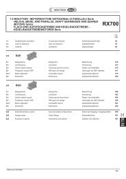
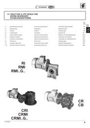
Riduttori a vite senza fine RI - RMI - CRI - CRMI - CR - CB<br />
Worm gearboxes RI - RMI - CRI - CRMI - CR - CB<br />
Schneckengetriebe RI - RMI - CRI - CRMI - CR - CB<br />
Riduttori universali a vite senza fine U-UI-UMI<br />
Worm gearboxes U-UI-UMI<br />
Schneckengetriebe U-UI-UMI<br />
Limitatore di coppia<br />
Torque limiter<br />
Rutschkupplung<br />
Rinvii angolari Z<br />
Right angle Z<br />
Winkelgetriebe Z<br />
Rinvii angolari ZL<br />
Right angle ZL<br />
Winkelgetriebe ZL<br />
Variatori meccanici VM<br />
Mechanical variators VM<br />
Mechanischen Verstellgetriebe VM<br />
Posizioni di montaggio<br />
Mounting position<br />
Montagepositionen<br />
WEB SITE MAP<br />
Gestione Revisioni Cataloghi STM<br />
Managing STM Catalog Revisions<br />
Management Wiederholt Kataloge STM<br />
CT16IGBD2 A1<br />
Pag.<br />
Page<br />
Seite<br />
A1<br />
B1<br />
C1<br />
D1<br />
E1<br />
F1<br />
G1<br />
Z1<br />
Z5<br />
Z6<br />
M1 M1<br />
M4 M4M5 M5
1.0 GENERALITA’<br />
1.1 Unita’ di misura<br />
Tab. 1.1<br />
A2<br />
1.1 Measurement units<br />
1.0 ALLGEMEINES<br />
SIMBOLO<br />
SYMBOL<br />
SYMBOL<br />
DEFINIZIONE DEFINITION DEFINITION<br />
Fr 1-2 Carico Radiale Radial load Radialbelastung N<br />
Fa 1-2 Carico assiale Axial load Axialbelastung N<br />
Dimensioni Dimensions Abmessungen mm<br />
FS Fattore di servizio Service factor Betriebsfaktor<br />
FS’<br />
Fattore di servizio<br />
motoriduttore<br />
Gear motors service factor Betriebsfaktor Getriebemotoren<br />
Kg Massa Mass Masse kg<br />
T2M Momento torcente riduttore Output torque Drehmoment Getriebe Nm<br />
T2 Momento torcente motorid. Gear motor torque Drehmoment Getriebemotor Nm<br />
P Potenza motore Gear unit power Leistung Getriebe kW<br />
Pto Potenza limite termico Limit thermal capacity Thermische Leistungsgrenze kW<br />
Pc Potenza corretta Correct power Tatsächliche Leistung kW<br />
P1 Potenza motoriduttore Gear motor power Leistung Getriebemotor kW<br />
P’ Potenza richiesta in uscita Output power Erforderliche<br />
Abtriebsleistung<br />
kW<br />
RD Rendimento dinamico Dynamic efficiency Dynamischer Wirkungsgrad<br />
RS Rendimento statico Static efficiency Statischer Wirkungsgrad<br />
ir Rapporto di trasmissione Ratio Übersetzungsverhältnis<br />
n1 Velocità albero entrata Input speed Antriebsdrehzahl<br />
min -1<br />
n2 Velocità albero in uscita Output speed Abtriebsdrehzahl<br />
Tc Temperatura ambiente Ambient temperature Umgebungstemperatur °C<br />
1.2 Velocità in entrata<br />
Tutte le prestazioni dei riduttori , variatori<br />
meccanici e rinvii angolari sono calcolate<br />
in base alle seguenti velocità in entrata:<br />
Tab. 1.2<br />
Riduttori<br />
Gearboxes<br />
Getriebe<br />
n1(rpm)<br />
a vite senza fine<br />
wormgearboxes<br />
Schneckengetriebe<br />
Velocità inferiori a 1400 min -1 ottenute con<br />
l’ausilio di riduzioni esterne o di azionamenti,<br />
sono sicuramente favorevoli al buon funzionamento<br />
del riduttore il quale può operare<br />
con temperature di funzionamento<br />
inferiori a vantaggio di tutto il cinematismo<br />
(in particolare nei riduttori a vite senza<br />
fine).<br />
E’ necessario però considerare che<br />
velocità molto basse non consentono<br />
un' efficace lubrificazione di tutto il<br />
gruppo, per cui tale eventualità dovrà<br />
essere segnalata per poter effettuare<br />
schermature dei cuscinetti superiori<br />
nei riduttori delle taglie maggiori o applicare<br />
sistemi di lubrificazione forzata<br />
(pompa di lubrificazione).<br />
1.0 GENERAL INFORMATION<br />
1.2 Input speed<br />
All performances of gearboxes and variators<br />
are calculated according to the following<br />
input speeds:<br />
a vite senza fine combinati<br />
combined wormgearboxes<br />
Kombinierte Schneckengetriebe<br />
a vite senza fine con<br />
precoppia<br />
Helical wormgearboxes<br />
Stirnrad Schneckengetriebe<br />
UI-RI-WI<br />
Speeds lower than 1400 rpm obtained by<br />
means of external reductions or drives,<br />
surely contribute to the good working of<br />
the gearbox which can operate at lower<br />
working temperatures to the advantage of<br />
the whole kinematic movement (in particular<br />
in case of the worm gearboxes).<br />
However, please note that very low<br />
speeds do not allow an efficacious lubrication<br />
of the whole unit. Therefore<br />
this case shall be indicated to screen<br />
the upper bearings of the gearboxes of<br />
larger sizes or to apply systems with<br />
forced lubrications (lubrication pump).<br />
1.1 Maßeinheiten<br />
UNITA’ DI MISURA<br />
MEASUREMENT UNIT<br />
MAßEINHEIT<br />
1.2 Antriebsdrehzahl<br />
1N=0.1daN � 0.1kg<br />
1Nm=0.1daNm�0.1kgm<br />
1kW = 1.36 HP (PS)<br />
1 min -1 = 6.283 rad.<br />
Alle Wirkungsgrade der Getriebe und Verstellgetriebe<br />
werden auf der Grundlage folgender<br />
Antriebsdrehzahlen berechnet:<br />
variatori meccanici<br />
mechanical<br />
variators<br />
Verstell-Getriebe<br />
rinvii angolari<br />
right angle gears<br />
Winkelgetriebe<br />
UI - RI - WI CRI-CWI CR VM - WM Z - ZL<br />
* Nei riduttori a vite senza fine, per situazioni<br />
con velocità di ingresso particolari,<br />
attenersi alla tabella sotto riportata che<br />
evidenzia le situazioni critiche.<br />
2800* — 2800 (max) 2800 (max) 2800 (max)<br />
1400 1400 1400 1400 1000<br />
900 — 900 900 900<br />
500 — 500 — 500<br />
* As far as worm reduction units are concerned,<br />
in situations with special input<br />
speeds, adhere to the table below that<br />
highlights any critical situations.<br />
* Bei den Schneckengetrieben ist unter<br />
Bedingungen mit besonderen Antriebsgeschwindigkeiten<br />
die nachstehend aufgeführte<br />
Tabelle zu beachten, die kritische<br />
Situationen hervorhebt.<br />
25 28 30 40 50 63 70 75 85 90 110 130 150 180<br />
1500 < n1 < 3000 OK OK OK OK OK Contattare il ns. servizio tecnico<br />
n1 > 3000<br />
Contact our technical dept<br />
Wenden Sie sich an unseren technischen Service<br />
Drehzahlen unter 1400 min -1 , die mit Hilfe<br />
äußerer Untersetzungen oder Antriebe erhalten<br />
werden, sind für den optimalen Betrieb<br />
des Getriebes vorteilhaft, denn so<br />
kann dieses mit niedrigen Betriebstemperaturen<br />
arbeiten, was sich zum Vorteil der<br />
gesamten Getriebegruppe auswirkt (insbesonders<br />
bei Schneckengetrieben).<br />
Es muß jedoch berücksichtigt werden,<br />
daß sehr niedrige Drehzahlen keine wirksame<br />
Schmierung der gesamten Gruppe<br />
zulassen. Wird mit solch niedrigen<br />
Drehzahlen gearbeitet, muß dies angegeben<br />
werden, damit wir bei den größeren<br />
Getrieben die oberen Lager abschirmen<br />
oder Zwangsschmiersysteme<br />
(Schmierpumpe) einsetzen können.<br />
CT16IGBD2.1
1.3 Fattore di servizio<br />
Il fattore di servizio FS permette di qualificare,<br />
in prima approssimazione, la tipologia<br />
dell’applicazione tenendo conto della<br />
natura del carico (A, B, C), della durata di<br />
funzionamento h/d (ore giornaliere) e del<br />
numero di avviamenti/ora. Il coefficiente<br />
così trovato dovrà essere uguale o inferiore<br />
al fattore di servizio del motoriduttore o<br />
del motorinvio angolare FS’ dato dal rapporto<br />
fra la coppia nominale del riduttore<br />
T2M indicata a catalogo e la coppia M’ richiesta<br />
dall’applicazione .<br />
I valori di FS indicati nella tab. 1.3, sono<br />
relativi all’azionamento con motore elettrico,<br />
se utilizzato un motore a scoppio, si<br />
dovrà tenere conto di un fattore di moltiplicazione<br />
1.3 se a più cilindri e 1.5 se monocilindro.<br />
Se il motore elettrico applicato è autofrenante,<br />
considerare un numero di avviamenti<br />
doppio di quello effettivamente<br />
richiesto.<br />
Tab. 1.3<br />
Classe di carico<br />
Load class<br />
Lastklasse<br />
A<br />
Carico uniforme<br />
Uniform load<br />
Gleichmäßig verteilte Last<br />
Classe di carico<br />
Load class<br />
Lastklasse<br />
B<br />
Carico con urti moderati<br />
Moderate shock load<br />
Last mit mäßigen Stößen<br />
Classe di carico<br />
Load class<br />
Lastklasse<br />
C<br />
Carico con forti urti<br />
Heavy shock load<br />
Last mit starken Stößen<br />
1.3 Service factor<br />
The service factor FS permits approximate<br />
qualification of the type of application, taking<br />
into account the type of load (A,B,C),<br />
length of operation h/d (hours/day) and the<br />
number of start-up/hour. The coefficient<br />
thus calculated must be equal or less than<br />
the motorgear unit service factor FS’ given<br />
by the rated torque of gear unit T2M as indicated<br />
in the catalogue and the torque M’<br />
required by the application.<br />
The FS values reported in Table 1.3 refer<br />
to a drive unit with an electric motor. If a<br />
combustion engine is used, a multiplication<br />
factor of 1.3 must be applied for a<br />
several-cylinder engine, 1.5 for a singlecylinder<br />
engine.<br />
If the electric motor applied is self-braking,<br />
consider twice the number of start-up than<br />
those actually required.<br />
1.3 Betriebsfaktor<br />
Mit Hilfe des Betriebsfaktors FS kann in einer<br />
ersten Annäherung das richtige Untersetzungsgetriebe<br />
für die gewünschte Anwendungsart<br />
ermittelt werden. Dabei sind<br />
folgende Werte zu beachten: Art der Last<br />
(A, B, C), Betriebsstunden pro Tag (h/d),<br />
Anzahl der Starts pro Stunde. Der so ermittelte<br />
Koeffizient sollte dem Betriebsfaktor<br />
FS’, der sich aus dem Verhältnis<br />
zwischen dem Nenndrehmoment des Getriebes<br />
T2M (s. Katalog) und dem für die<br />
Anwendung erforderlichen Drehmoment<br />
M’ ergibt, entweder entsprechen oder<br />
niedriger liegen.<br />
Die FS-Werte, die in Tabelle 1.3 angegeben<br />
werden, beziehen sich auf den Antrieb<br />
mit Elektromotor. Wird ein Verbrennungsmotor<br />
verwendet, so ist bei mehreren Zylindern<br />
ein Multiplikationsfaktor von 1,3<br />
und bei einem Einzylindermotor ein Faktor<br />
von 1,5 zu berücksichtigen.<br />
Ist der verwendete Elektromotor ein<br />
Bremsmotor, so ist die Zahl der tatsächlichen<br />
Startvorgänge zu verdoppeln.<br />
FATTORE DI SERVIZIO / SERVICE FACTOR / BETRIEBSFAKTOR<br />
FS<br />
N. AVVIAMENTI/ORA / N. START-UP/HOUR / ANZAHL DER STARTVORGÄNGE PRO STUNDE<br />
h/d<br />
2 4 8 16 32 63 125 250 500<br />
4 0.85 0.9 0.9 0.93 0.98 1.03 1.06 1.1 1.2<br />
8 1.0 1.0 1.1 1.1 1.15 1.2 1.24 1.3 1.3<br />
16 1.2 1.2 1.25 1.3 1.35 1.45 1.5 1.5 1.55<br />
24 1.4 1.4 1.45 1.5 1.55 1.6 1.65 1.7 1.75<br />
APPLICAZIONI / APPLICATIONS / ANWENDUNGEN<br />
Agitatori per liquidi puri Pure liquid agitators Rührwerke für reine Flüssigkeiten<br />
Alimentatori per fornaci Fournace feeders Beschickungsvorrichtungen für<br />
Brennöfen<br />
Alimentatori a disco Disc feeders Telleraufgeber<br />
Filtri di lavaggio con aria Air laundry filters Spülluftfilter<br />
Generatori Generators Generatoren<br />
Pompe centrifughe Centrifugal pumps Kreiselpumpen<br />
Trasportatori con carico uniforme Uniform load conveyors Förderer mit gleichmäßig verteilter Last<br />
N. AVVIAMENTI/ORA / N. START-UP/HOUR / ANZAHL DER STARTVORGÄNGE PRO STUNDE<br />
h/d<br />
2 4 8 16 32 63 125 250 500<br />
4 1.11 1.12 1.15 1.19 1.23 1.28 1.32 1.36 1.40<br />
8 1.29 1.31 1.34 1.40 1.45 1.51 1.56 1.60 1.64<br />
16 1.54 1.56 1.59 1.65 1.71 1.78 1.84 1.90 1.96<br />
24 1.73 1.75 1.80 1.90 1.97 2.05 2.10 2.16 2.22<br />
APPLICAZIONI / APPLICATIONS / ANWENDUNGEN<br />
Agitatori per liquidi e solidi Liquid and solid agitators Rührwerke für Flüssigkeiten und Feststoffe<br />
Alimentatori a nastro Belt conveyors Bandförderer<br />
Argani con medio servizio Medium service winches Mittlere Winden<br />
Filtri con pietre e ghiaia Stone and gravel filters Stein- und Kiesfilter<br />
Viti per espulsione acqua Dewatering screws Abwasserschnecken<br />
Flocculatori Flocculator Flockvorrichtungen<br />
Filtri a vuoto Vacuum filters Vakuumfilter<br />
Elevatori a tazze Bucket elevators Becherwerke<br />
Gru Cranes Krane<br />
N. AVVIAMENTI/ORA / N. START-UP/HOUR / ANZAHL DER STARTVORGÄNGE PRO STUNDE<br />
h/d<br />
2 4 8 16 32 63 125 250 500<br />
4 1.46 1.46 1.48 1.51 1.57 1.61 1.62 1.64 1.66<br />
8 1.71 1.71 1.73 1.76 1.82 1.86 1.87 1.89 1.89<br />
16 2.04 2.05 2.07 2.10 2.15 2.20 2.21 2.23 2.23<br />
24 2.31 2.31 2.33 2.36 2.42 2.48 2.52 2.54 2.56<br />
APPLICAZIONI / APPLICATIONS / ANWENDUNGEN<br />
Argani per servizio pesante Heavy duty hoists Winden für schwere Lasten<br />
Estrusori Extruders Extruder<br />
Calandre per gomma Crusher rubber calenders Gummikalander<br />
Presse per mattoni Brick presses Ziegelpressen<br />
Piallatrici Planing machine Hobelmaschinen<br />
Mulini a sfera Ball mills Kugelmühlen<br />
CT16IGBD2 A3<br />
A
1.3 Fattore di servizio<br />
Nel caso di riduttori a vite senza fine, occorre<br />
tener conto della temperatura ambiente<br />
(Tamb): il fattore di servizio va allora<br />
corretto come segue:<br />
Tab. 1.4<br />
Nel caso di variatore meccanico è necessario<br />
evidenziare inoltre che il numero di<br />
avviamenti massimo consentito senza<br />
provocare conseguenze sulla durata del<br />
variatore, non deve superare gli 8 - 10 al<br />
minuto<br />
A4<br />
1.3 Service factor<br />
Ambient temperature must also be taken<br />
into consideration when choosing<br />
wormgearboxes (Tamb): the service factor<br />
must be corrected as follows:<br />
Tamb<br />
Fattore di servizio / Service factor / Betriebsfaktor<br />
30 � 40 °C FS x 1.10<br />
40 � 50 °C FS x 1.2<br />
50 � 60 °C FS x 1.4<br />
About mechanical variator, note that the<br />
maximum number of starts allowed to preserve<br />
variator life is 8 - 10 starts per minute.<br />
1.3 Betriebsfaktor<br />
Im Falle der Schneckengetriebe muß die<br />
Raumtemperatur (Traum): berücksichtigt<br />
werden: der Betriebsfaktor muß also wie<br />
folgt bereinigt werden:<br />
� 60 °C Interpellare ns. Assistenza Tecnica / Contact our Technical Assistance Service / Bitte technischen Service hinzuziehen<br />
1.4 Rendimento<br />
(ed irreversibilità )<br />
Nei variatori meccanici vale circa 0.84 alla<br />
velocità massima.<br />
Nei rinvii angolari il rendimento dinamico<br />
RD può essere considerato pari a<br />
0.94-0.97.<br />
Nei riduttori a vite senza fine invece, è opportuno<br />
definire il rendimento in base al<br />
rapporto di riduzione distinguendo chiaramente<br />
fra il rendimento dinamico (questi<br />
valori sono riportati nelle tabelle delle prestazioni)<br />
e il rendimento statico (tab. 1.6).<br />
ll rendimento dinamico RD aumenta con il<br />
crescere dell’angolo dell’elica (bassi rapporti<br />
di riduzione), con il passare da oli minerali<br />
a sintetici e con l’incremento della<br />
velocità di strisciamento. Durante la fase<br />
di rodaggio il suo valore risulta essere<br />
sensibilmente inferiore rispetto a quello riportato<br />
nelle tabelle delle prestazioni.<br />
Il rendimento statico RS o rendimento<br />
dell’avviamento, è molto importante, al<br />
fine di una corretta scelta del riduttore,<br />
per quelle applicazioni in cui non si<br />
raggiungono mai le condizioni di regime<br />
(servizi intermittenti).<br />
Un riduttore è irreversibile staticamente<br />
(non azionabile dall’albero lento) quando il<br />
suo RS è minore di 0.5. In presenza di urti<br />
e vibrazioni tale condizione può non essere<br />
verificata.<br />
Un riduttore è irreversibile dinamicamente<br />
(blocco istantaneo della rotazione della<br />
vite qualora non sia più presente la causa<br />
della rotazione stessa) quando il suo RD è<br />
minore di 0.5.<br />
1.4 Efficiency<br />
(and irreversibility)<br />
Equal to 0.84 in case of variators at maximum<br />
speed.<br />
In right angle drives the dynamic efficiency<br />
RD can be considered equal to 0.94 and<br />
0.97<br />
It is advisable to determine the efficiency<br />
according to the reduction ratio in the<br />
worm gearboxes and to make a distinction<br />
between the dynamic efficiency<br />
(these values are shown in the performance<br />
tables)and static efficiency (see<br />
tab. 1.6).<br />
Dynamic efficiency RD increases gradually<br />
with an increase of the helix angle<br />
(low reduction04 ratios), with a change<br />
from mineral to synthetic lubricants and<br />
with an increase of rubbing speed. During<br />
running in period RD value is substantially<br />
inferior to the one listed in the performance<br />
table.<br />
Static efficiency RS or starting efficiency<br />
is very important with respect to<br />
the correct selection of the gearbox especially<br />
on applications where the optimal<br />
operating conditions are never<br />
attained (intermittent duty).<br />
A gearbox is statically irreversible (cannot<br />
be put into operation by output shaft),<br />
when its RS is less than 0.5. In the case of<br />
shocks or vibrations this can happen anyway.<br />
A gearbox is dynamically irreversible (instantaneous<br />
stop lock of wormshaft<br />
rotation if the cause of the same rotation is<br />
not present anymore), when its RD value<br />
is less than 0.5.<br />
Um die maximale Lebensdauer zu gewährleisten,<br />
sollten maximal 8-10 Schaltungen<br />
pro Minute getätigt werden.<br />
1.4 Wirkungsgrad<br />
(und Selbsthemmung)<br />
Mechanischen Verstellgetrieben ca. 0,84<br />
bei Maximalgeschwindigkeit.<br />
Der Wirkungsgrad der Winkelgetriebe<br />
beträgt 0.94-0.97. Bei Schneckengetrieben<br />
ist es hingegen zweckmäßig, den Wirkungsgrad<br />
ausgehend vom<br />
Untersetzungsverhältnis zu bestimmen,<br />
wobei zwischen dynamischem Wirkungsgrad<br />
(die Werte sind jeweils in den<br />
Leistungstabellen aufgeführt) und statischem<br />
Wirkungsgrad zu unterscheiden ist<br />
(siehe tab 1.6) . Der dynamische Wirkungsgrad<br />
RD erhöht sich bei einer Vergrößerung<br />
des Steigungswinkels (bei<br />
niedrigen Untersetzungsverhältnissen),<br />
bei der Verwendung von synthetischen<br />
anstatt Mineralölen und bei Erhöhung der<br />
Gleitgeschwindigkeit. Während der Einlaufzeit<br />
ist der Wert wesentlich niedriger als<br />
derjenige in den Leistungstabellen.<br />
Der statische Wirkungsgrad RS oder<br />
Anlaufwirkungsgrad ist bei der richtigen<br />
Wahl des Untersetzungsgetriebes<br />
sehr wichtig, speziell bei solchen<br />
Anwendungen, bei denen der optimale<br />
Betriebszustand nicht erreicht wird<br />
(Aussetzbetrieb).<br />
Ein Getriebe ist statisch selbsthemmend<br />
(kann von der Abtriebswelle nicht in Gang<br />
gesetzt werden), wenn sein statischer Wirkungsgrad<br />
(RS) unter 0.5 liegt. Bei Stößen<br />
oder Vibrationen kann dies jedoch trotzdem<br />
vorkommen. Ein Getriebe ist dynamisch<br />
selbsthemmend (sofortiges<br />
Blockieren der Schnekke, wenn die Ursache<br />
dieser Drehung nicht mehr vorhanden<br />
ist) wenn sein dynamischer Wirkungsgrad<br />
RD unter 0.5<br />
.<br />
CT16IGBD2
1.4 Rendimento<br />
(ed irreversibilità )<br />
In Tab. 1.5 sono riportate le fasce di reversibilità<br />
ed irreversibilità (dinamiche e statiche)<br />
in funzione delle caratteristiche delle<br />
dentature dei riduttori a vite senza fine.<br />
Poichè la totale irreversibilità è praticamente<br />
impossibile da realizzarsi, è sempre<br />
preferibile, in applicazioni che lo necessitano,<br />
ricorrere all’utilizzo di freni esterni.<br />
Analogamente al caso dinamico, anche il<br />
rendimento statico RS (vedi tab. 1.6) tende<br />
ad aumentare durante la fase di rodaggio.<br />
Esso tiene conto della resistenza al moto<br />
offerta nell'ingranamento vite-corona e sviluppata<br />
nei paraoli e cuscinetti; data<br />
l'incertezza di queste componenti, si capisce<br />
che questi dati sono solo indicativi.<br />
Tab. 1.5<br />
UI-RI<br />
UMI - RMI<br />
WI - WMI<br />
CRI - CWI<br />
CRMI - CWMI<br />
CR<br />
CB<br />
7<br />
7.5<br />
7<br />
7.5<br />
La Tab. 1.6 riporta il valore del rendimento<br />
statico attribuito ad ogni rapporto di<br />
riduzione.<br />
Tab. 1.6<br />
10 15 20<br />
Rapporti di riduzione / Reduction ratios/ Übersetzungsverhältnis (ir)<br />
25<br />
28<br />
30<br />
CT16IGBD2 CT16IGBD2.1<br />
A5<br />
40<br />
Rapporti di riduzione / Reduction ratios/ Übersetzungsverhältnis (i1, i2)<br />
10 15 20<br />
25<br />
28<br />
30<br />
40<br />
49<br />
50<br />
49<br />
50<br />
56<br />
60<br />
56<br />
60<br />
70 80 100<br />
70 80 100<br />
Rapporti di riduzione / Reduction ratios/ Übersetzungsverhältnis (i2)<br />
15 28 49 100<br />
Reversibilità totale<br />
Total reversibility<br />
Totale Reversibilität<br />
1.4 Efficiency<br />
(and irreversibility)<br />
In Table 1.5 reversibility and irreversibility<br />
range of values (dynamic and static) is indicated<br />
with respect to toothing characteristics.<br />
Since total irreversibility is practically<br />
impossible to realize, it is always preferable<br />
to adopt external measures, such as<br />
brakes, in order to guarantee irreversibility<br />
if required by particular applications.<br />
As dynamic efficiency, also static efficiency<br />
RS (see tab. 1.6) is going to increase<br />
during running period. It include many<br />
components: gear meshing, oilseals and<br />
bearings.<br />
As the uncertainty of this components, we<br />
give this data as approximative.<br />
Zona di incertezza<br />
Uncertainty zone<br />
Übergangsbereich<br />
Table 1.6 shows the static efficiency<br />
given to every reduction ratio.<br />
1.4 Wirkungsgrad<br />
(und Selbsthemmung)<br />
Irreversibilità statica /Reversibilità dinamica<br />
Static irreversibility / Dynamic reversibility<br />
Statische Selbsthemmung / Dynamische Reversibilität<br />
Valori del rendimento statico RS (%) / Static efficiency RS (%) / Statischer Wirkungsgrad RS (%)<br />
In Tabelle 1.5 werden die (dynamischen<br />
und statischen) Reversibilitäts- und<br />
Selbsthemmungswerte je nach Untersetzung<br />
angegeben.<br />
Da eine vollständige Selbsthemmung<br />
praktisch nicht möglich ist, wird empfohlen,<br />
in entsprechenden Anwendungen externe<br />
Bremsen einzusetzen.<br />
Auch der statische Wirkungsgrad RS<br />
(siehe Tabelle 1.6) tendiert in der Einlaufzeit<br />
anzusteigen, genau wie der dynamische<br />
Wert. Dieser Wert berücksichtigt den<br />
Anlaufwiderstand von Schnecke- Schneckenwelle<br />
sowie in den Öldichtungen und<br />
Lagern. Aufgrund der nicht exakten Bestimmbarkeit<br />
dieser Faktoren sind diese<br />
Daten lediglich richtungsweisend.<br />
In Tabelle 1.6 ist der jedem Untersetzungsverhältnis<br />
zugeordnete statische Wirkungsgrad<br />
aufgeführt.<br />
ir 7 7.5 10 15 20 25 28 30 40 49 50 56 60 70 80 100<br />
WI 25 - 71 68 61 56 - 46 41 36 - 36 - 34 - - -<br />
RI 28 70 - 67 61 57 - 46 - 41 38 - 36 - 32 27 25<br />
WI 30 - 67 63 55 50 43 39 35 31 27 - 23 -<br />
UI-RI40 72 - 69 62 55 - 48 - 39 36 - 34 - 27 26 25<br />
WI 40 - 71 67 60 55 51 - 45 40 - 36 - 32 - 28 24<br />
UI-RI50 73 - 70 68 60 - 51 - 46 42 - 40 - 36 30 28<br />
WI 50 - 70 66 59 55 51 - 44 39 - 35 - 32 - 27 23<br />
UI-RI63 74 - 70 64 60 - 50 - 46 42 - 40 - 36 33 29<br />
WI 63 - 71 67 60 55 51 - 45 40 - 36 - 33 - 28 24<br />
RI 70 74 - 70 64 60 - 49 - 45 40 - 39 - 34 31 29<br />
UI 75 73 - 70 62 60 - 49 - 45 40 - 39 - 35 33 29<br />
WI 75 - 71 68 61 57 53 - 46 42 - 38 - 35 - 29 26<br />
RI 85 73 - 70 64 62 - 48 - 46 41 - 43 - 38 35 30<br />
UI 90 72 - 70 65 62 - 50 - 47 43 - 42 - 38 36 32<br />
WI 90 - 73 70 64 60 56 - 49 45 - 41 - 38 - 32 28<br />
RI 110 74 - 72 64 63 - 52 - 48 45 - 44 - 39 37 33<br />
WI 110 - 72 69 63 62 59 - 48 48 - 44 - 41 - 36 32<br />
RI 130 74 - 72 68 64 - 51 - 47 44 - 45 - 40 39 34<br />
WI 130 - 72 69 63 61 58 - 49 46 - 43 - 39 - 34 30<br />
RI 150 75 - 73 68 65 - 53 - 48 46 - 47 - 41 39 36<br />
WI 150 - 73 71 66 60 57 - 54 45 - 42 - 39 - 33 29<br />
RI 180 75 - 73 69 65 - 54 - 49 46 - 47 - 41 39 35<br />
CR 40 — — 62 — 48 — 36 — — — 25<br />
CR 50 — — 68 — 51 — 42 — — — 28<br />
CR 70 — — 64 — 49 — 40 — — — 29<br />
CR 85 — — 64 — 48 — 41 — — — 30<br />
CR 110 — — 64 — 52 — 45 — — — 33<br />
A
1.5 Gioco angolare<br />
Nella tab 1.7 riportiamo i valori del gioco<br />
angolare riscontrabili sull’albero in uscita<br />
nei riduttori a vite senza fine.<br />
Questi valori, espressi in primi di grado (‘),<br />
sono indicativi in quanto possono variare<br />
in funzione della temperatura e dell’usura.<br />
Su richiesta, per applicazioni particolari,<br />
si possono fornire riduttori con<br />
giochi angolari inferiori.<br />
Tab. 1.7<br />
UI-RI<br />
RI - RMI<br />
A6<br />
CRI<br />
CRMI<br />
Gioco angolare<br />
Backlash<br />
Flankenspiel (')<br />
CB<br />
CR<br />
1.5 Backlash<br />
Values of the output shaft backlash on<br />
wormgearboxes are shown in table 1.7.<br />
Such values are expressed in minute (')<br />
and are approximate as they can change<br />
according to temperature and wear.<br />
For particular applications, gearboxes<br />
with low backlash adjustable backlash<br />
are available upon request.<br />
Gioco angolare<br />
Backlash<br />
Flankenspiel (')<br />
Min Max Min Max<br />
28 .../28 5.5’ 17’<br />
40 .../40 4.5’ 14’ 40 4.5’ 14’<br />
50 .../50 3.5’ 12.5’ 50 3.5’ 12.5’<br />
63 .../63 3.5’ 12.5’<br />
70 .../70 3’ 11.5’ 70 3’ 11.5’<br />
75 — 3’ 11’<br />
85 .../85 3’ 11’ 85 3’ 11’<br />
90 — 3' 10'<br />
110 .../110 2.5’ 9.5’ 110 2.5’ 9.5’<br />
130 .../130 2.5' 9.5'<br />
150 .../150 2.5' 9.5'<br />
180 .../180 2.5' 9.5'<br />
1.5 Flankenspiel<br />
1.6 Lubrificazione 1.6 Lubrication 1.6 Schmierung<br />
La lubrificazione dei riduttori, variatori e<br />
rinvii angolari è consentita mediante un sistema<br />
misto bagno olio e sbattimento, che<br />
garantisce normalmente la lubrificazione<br />
di tutti i componenti interni al riduttore, rinvio<br />
angolare e/o variatore.<br />
Per quelle posizioni di montaggio caratterizzate<br />
da assi di rotazione verticali,<br />
vengono adottate particolari soluzioni al<br />
fine di garantire una buona lubrificazione<br />
anche degli organi presenti nelle posizioni<br />
più sfavorevoli.<br />
I riduttori a vite senza fine sono caratterizzati<br />
da una elevata componente di strisciamento,<br />
variabile a seconda delle<br />
caratteristiche di dentatura dell' ingranaggio<br />
e delle velocità di rotazione del cinematismo,<br />
e per questo motivo necessitano<br />
di una accurata lubrificazione. Per questo<br />
tipo di riduttori usiamo e consigliamo oli a<br />
base sintetica, che migliorano il rendimento<br />
e possiedono una maggiore stabilità di<br />
viscosità. E’ importante che gli additivi<br />
E.P. presenti negli oli siano blandi e non<br />
agressivi nei confronti del bronzo e delle<br />
guarnizioni. La lubrificazione a grasso è<br />
consigliata solo con grassi a base sintetica<br />
e molto fluidi (NLGI 00); vengono preferiti<br />
per esercizi con elevati urti e per funzionamenti<br />
intermittenti.<br />
Usando il grasso anzichè l’olio, si ha un<br />
minor smaltimento del calore, una riduzione<br />
del rendimento, un incremento dell’usura<br />
e una minore lubrificazione di tutti i<br />
componenti.<br />
Gearboxes and variators lubrication is provided<br />
trough a combination of oil immersion<br />
and oil-splash patterns, which<br />
normally guarantees the lubrication of all<br />
internal components.<br />
For some mounting positions, typically<br />
those featuring a vertical shaft, provisions<br />
are made to guarantee lubrication of even<br />
the least favourably located drive components.<br />
Wormgearboxes are characterized by an<br />
high sliding velocity, which depends by<br />
teeth's characteristics and input speed,<br />
and this is why they need a proper lubrication.<br />
For this kind of gearboxes STM use and<br />
suggest synthetic based oils, which increase<br />
the dynamic efficiency and guarantee<br />
longer duration and higher viscosity<br />
stability.<br />
It is very important that E.P. additives present<br />
in lubricants are not aggressive towards<br />
bronze and oilseals.<br />
Grease lubrication is advisable only if<br />
synthetic based and fluid grease is used<br />
(NLGI 00). It is preferable to use such a<br />
lubrication when having heavy shocks and<br />
intermittent duties.<br />
Grease used in place of oil contributes to<br />
a more difficult elimination of heat, a lower<br />
efficiency and an increase in wear and<br />
tear as well as a lower lubrication of all<br />
components.<br />
Z<br />
Gioco angolare<br />
Backlash<br />
Flankenspiel (')<br />
Für die Schneckengetriebe ist das Spiel<br />
der Abtriebswelle in Tabelle 1.7 (in Winkelminuten<br />
’) aufgeführt.<br />
Diese Werte sind Richtwerte, da sie von<br />
der Temperatur und vom Verschleiß abhängen.<br />
Für spezielle Anwendungen liefern wir<br />
auf Wunsch spielfreie Untersetzungsgetriebe<br />
bzw. mit einstellbarem Flankenspiel.<br />
ZL<br />
Gioco angolare<br />
Backlash<br />
Flankenspiel (')<br />
Min Max Min Max<br />
Contattare il ns. servizio tecnico<br />
Contact our technical dept.<br />
Wenden Sie sich an unseren technischen Vertriebsservice<br />
Die Schmierung der Getriebe und der Variatoren<br />
erfolgt über ein Mischverfahren<br />
mit Ölbad- und Tauchbadschmierung. Dadurch<br />
kann in der Regel die Schmierung<br />
aller internen Bestandteile des Getriebes<br />
oder des Variators gewährleistet werden.<br />
Bei Montagepositionen mit vertikalen<br />
Drehachsen werden spezielle Lösungen<br />
angewandt, um auch die Bestandteile in<br />
schwer erreichbaren Positionen ausreichend<br />
zu schmieren.<br />
Die Schneckengetriebe weisen eine hohe<br />
Reibungskomponente auf, die jeweils hinsichtlich<br />
der Untersetzung und der Drehgeschwindigkeit<br />
des Getriebes variiert.<br />
Daher erfordert dieser Getriebetyp eine<br />
sorgfältige Schmierung. Empfehlenswert<br />
ist synthetisches Öl, das den Wirkungsgrad<br />
steigert und eine höhere Stabilität im<br />
Hinblick auf die Viskosität aufweist.<br />
Wichtig ist, daß die E.P.-Additive der Öle<br />
mild sind und die Bronze sowie die Dichtungen<br />
nicht angreifen.<br />
Für die Schmierung mit Fett empfehlen<br />
wir, nur hochviskose (NLGI 00) Fette mit<br />
synthetischer Base zu verwenden, diese<br />
werden für den aussetzenden Betrieb vorgezogen.<br />
Wird Fett anstelle von Öl verwendet, so<br />
resultiert hieraus eine verminderte<br />
Schmierung aller Komponenten, eine<br />
niedrigere Wärmeabgabe, ein niedrigerer<br />
Wirkungsgrad und ein höherer Verschleiß.<br />
CT16IGBD2
Tutti i riduttori con limitatore di coppia devono<br />
essere lubrificati ad olio: la lubrificazione<br />
a grasso non è ammessa.<br />
I riduttori delle taglie di bassa potenza e i<br />
rinvii angolari (ad eccezione del rinvio angolare<br />
grandezza 331 che viene fornito<br />
con grasso) vengono forniti completi d'olio<br />
SHELL a base sintetica tipo Tivela S 320:<br />
tali riduttori sono a lubrificazione cosidetta<br />
"long life" ossia non richiedono alcuna sostituzione<br />
dell'olio per tutto il loro arco di<br />
vita.<br />
I riduttori delle taglie superiori vengono invece<br />
forniti a secco ed è quindi compito<br />
dell'utilizzatore riempirli con olio adeguato<br />
(vedere tab. 1.8), prima della messa in<br />
opera, servendosi dei tappi di carico, scarico,<br />
livello e sfiato, della quantità corrispondente<br />
alla specifica posizione di<br />
montaggio.<br />
Se richiesti completi di lubrificante, verranno<br />
forniti con olio sintetico SHELL Tivella S 320.<br />
Gli oli disponibili appartengono generalmente<br />
a tre grandi famiglie:<br />
1) Oli minerali<br />
2) Oli sintetici Poli-Alfa-Olefine<br />
3) Oli sintetici Poli-Glicole<br />
La scelta più appropriata è generalmente<br />
legata alle condizioni di impiego. riduttori<br />
non particolarmente caricati e con un ciclo<br />
di impiego discontinuo. senza escursioni<br />
termiche importanti, possono certamente<br />
essere lubrificati con olio minerale.<br />
Nei casi di impiego gravoso, quando i riduttori<br />
saranno prevedibilmente caricati<br />
molto ed in modo continuativo, con conseguente<br />
prevedibile innalzamento della<br />
temperatura, è bene utilizzare lubrificanti<br />
sintetici tipo polialfaolefine (PAO).<br />
Gli oli di tipo poliglicole (PG) sono da utilizzare<br />
strettamente nel caso di applicazioni<br />
con forti strisciamenti fra i contatti, ad<br />
esempio nelle viti senza fine. Debbono essere<br />
impiegati con grande attenzione poiché<br />
non sono compatibili con gli altri oli e<br />
sono invece completamente miscibili conl'acqua.<br />
Questo fenomeno è particolarmente<br />
pericoloso poiché non si nota, ma<br />
deprime velocemente le caratteristiche lubrificanti<br />
dell'olio.<br />
Oltre a questi già menzionati, ricordiamo<br />
che esistono gli oli per l'industria alimentare.<br />
Questi trovano specifico impiego nell'industria<br />
alimentare in quanto sono<br />
prodotti speciali non nocivi alla salute. Vari<br />
produttori forniscono oli appartenenti a tutte<br />
le famiglie con caratteristiche molto simili.<br />
CT16IGBD2.1<br />
All gearboxes incorporating torque limiters<br />
will have to be lubricated with oil: grease<br />
lubrication is not admitted.<br />
The gearboxes of smaller size and right<br />
angle drives (only right angle drive size<br />
331 is supplied with long-life grease) are<br />
supplied with SHELL synthetic based oil<br />
filled, type Tivela S 320. This gearboxes<br />
are filled with a "long life" poliglycol based<br />
lubricant: this means they are maintenance-free<br />
and do not require oil changes during<br />
the operating life.<br />
Larger size units are instead supplied dry<br />
and it will be the customer care to fill them<br />
with appropriate lubricant (tab. 1.8) prior to<br />
putting them into operation, using fill, drain,<br />
level and breather plugs and with quantity<br />
according to the particular mounting<br />
position.<br />
If customer requests supply of gearbox<br />
with lubricant, we shall supply them with<br />
syntheic oil SHELL Tivella S 320.<br />
Available oils are typically grouped into<br />
three major classes:<br />
1) Mineral oils<br />
2) Poly-Alpha-Olefin synthetic oils<br />
3) Polyglycol synthetic oils<br />
Oil is normally selected in accordance with<br />
environmental and operating conditions.<br />
Mineral oil is the appropriate choice for<br />
moderate load, non-continuous duty applications<br />
free from temperature extremes.<br />
In severe applications, where gear units<br />
are to operate under heavy loads in continuous<br />
duty and high temperatures are expected,<br />
synthetic Poly-Alpha-Olefin oils<br />
(PAO) are the preferred choice.<br />
Polyglycol oils (PG) should only be used in<br />
applications involving high sliding friction,<br />
as is the case with worm shafts. These<br />
particular oils should be used with great<br />
care, as they are not compatible with other<br />
oils, but are totally mixable with water. The<br />
oil mixed with water cannot be told from<br />
uncontamined oil, but will degrade very rapidly.<br />
In addition to the oils mentioned above,<br />
there are food-grade oils. These are special<br />
oils harmless to human health for use<br />
in the food industry. Oils with similar characteristics<br />
are available from a number of<br />
manufacturers.<br />
Alle Getriebe mit Rutschkupplung müssen<br />
mit Öl geschmiert werden: Eine<br />
Fettschmierung ist hier nicht zulässig.<br />
Alle Getriebe im niedrigen Leistungsbereich<br />
sowie alle Winkelgetriebe (mit<br />
Ausnahme der Grösse 331, welches mit<br />
Fettfüllung geliefert wird) sind bei der<br />
Lieferung bereits mit Öl gefüllt. Dabei wird<br />
der Typ Tivela S 320 auf synthetischer Basis.<br />
Diese Getriebe sind “Lebensdauer”geschmiert,<br />
d.h. sie erfordern während<br />
ihrer gesamten Lebensdauer keinen<br />
Ölwechsel. Die Getriebe des höheren<br />
Leistungsbereichs werden hingegen ohne<br />
werkseitige Ölfüllung geliefert (Tab. 1.8).<br />
Der Benutzer hat vor der Inbetriebnahme<br />
unter Verwendung der Füll-, Ablaß-,<br />
Entlüftungs- und Füllstan- dsstopfen<br />
richtige Ölmenge einzufüllen, die für die<br />
jeweilige Montageposition erforderlich ist.<br />
Falls diese Getriebe mit Schmiermittelfüllung<br />
angefordert werden, werden sie<br />
mit dem Synthetiköl SHELL Tivella S 320<br />
geliefert.<br />
Die verfügbaren Öle gehören im Allgemeinen<br />
drei großen Familien an:<br />
1) Mineralöle<br />
2) Polyalphaolefine-Synthetiköle<br />
3) Polyglykol-Synthetiköle<br />
Die angemessene Wahl ist im Allgemeinen<br />
an die Einsatzbedingungen gebunden.<br />
Getriebe, die keinen besonders<br />
schweren Belastungen ausgesetzt sind<br />
und einem unregelmäßigen Einsatzzyklus<br />
unterliegen, ohne starke thermische<br />
Ausschläge, können problemlos mit Mineralöl<br />
geschmiert werden. Bei einem Einsatz<br />
unter harten Bedingungen, d.h. wenn<br />
die Getriebe stark und andauernd belastet<br />
werden, woraus sich ein sicherer Temperaturanstieg<br />
ergibt, sollten Synthetiköle,<br />
Typ Polyalphaolefine (PAO), verwendet<br />
werden.<br />
Die Öle, Typ Polyglykole (PG), sind<br />
ausschließlich für einen Einsatz ausgelegt,<br />
bei denen es zu starken Reibungen zwischen<br />
den in Kontakt stehenden Elementen<br />
kommt, z.B. bei Schnecken. Bei ihrem<br />
Einsatz in besondere Aufmerksamkeit erforderlich,<br />
da sie nicht mit anderen Ölen<br />
kompatibel sind, sich jedoch vollständig<br />
mit Wasser vermischen lassen. Diese Tatsache<br />
erweist sich daher als besonders<br />
gefährlich, da sie sich nicht feststellen<br />
lässt, jedoch die Schmiereigenschaften<br />
des Öls bereits nach kurzer Zeit unterdrückt.<br />
Über die bereits genannten Öle hinaus,<br />
gibt es auch Öle, die speziell für die Lebensmittelindustrie<br />
ausgelegt sind. Diese<br />
finden demzufolge dort ihren Einsatz, da<br />
es sich dabei um spezielle Produkte handelt,<br />
die für die Gesundheit unschädlich<br />
sind. Die den jeweiligen Familien angehörigen<br />
Ölsorten werden von verschiedenen<br />
Herstellern angeboten; sie weisen jeweils<br />
sehr ähnliche Eigenschaften auf.<br />
A7<br />
A
La Tab. 1.8 è utile per la selezione dei lubrificanti<br />
per riduttori da utilizzare in base<br />
alla loro stabilità alle varie temperature.<br />
Tab. 1.8<br />
A8<br />
Produttore<br />
Manufacturer<br />
Hersteller<br />
Temp. ambiente<br />
Amb. temp.<br />
Umgebungstemperatur<br />
Tc [°C]<br />
AGIP<br />
Oli Minerali<br />
Mineral oils<br />
Mineralöle<br />
Oli Sintetici Polialfaolefine (PAO)<br />
Poly-Alpha-Olefin synthetic oils (PAO)<br />
Polyalphaolefine- Synthetiköle (PAO)<br />
Oli Sintetici Poliglicoli (PG)<br />
Polyglycol synthetic oils(PG)<br />
Polyglykol-Synthetiköle (PG)<br />
ISO VG ISO VG ISO VG<br />
220 320 460 150 220 320 150 220 320 460<br />
-5° ÷ 25° 0° ÷ 35° 10° ÷ 45° -10° ÷ 25° -5° ÷35° 0° ÷ 50° -10° ÷ 25° -5° ÷ 35° 0° ÷ 50° 10° ÷ 60°<br />
Blasia<br />
220<br />
Blasia<br />
320<br />
Blasia<br />
460<br />
-<br />
Blasia SX<br />
220<br />
Blasia SX<br />
320<br />
Blasia S<br />
150<br />
Blasia S<br />
220<br />
Blasia S<br />
320<br />
Blasia S<br />
320<br />
ARAL<br />
Degol BG<br />
220 Plus<br />
Degol BG<br />
320 Plus<br />
Degol BG<br />
460 Plus<br />
Degol PAS<br />
150<br />
Degol PAS<br />
220<br />
Degol PAS<br />
320<br />
Degol GS<br />
150<br />
Degol GS<br />
220<br />
Degol GS<br />
320<br />
Degol GS<br />
460<br />
BP<br />
Energol<br />
GR-XP 220<br />
Energol<br />
GR-XP 320<br />
Energol<br />
GR-XP 460<br />
Enersyn<br />
EPX 150<br />
Enersyn<br />
EPX 220<br />
Enersyn<br />
EPX 320<br />
Enersyn<br />
SG 150<br />
Enersyn<br />
SG-XP 220<br />
Enersyn<br />
SG-XP 320<br />
Enersyn<br />
SG-XP 460<br />
CASTROL<br />
Alpha SP<br />
220<br />
AlphaSP<br />
320<br />
AlphaSP<br />
460<br />
Alphasyn EP<br />
150<br />
Alphasyn EP<br />
220<br />
Alphasyn EP<br />
320<br />
Alphasyn PG<br />
150<br />
Alphasyn PG<br />
220<br />
Alphasyn PG<br />
320<br />
Alphasyn PG<br />
460<br />
CHEVRON<br />
Ultra Gear<br />
220<br />
Ultra Gear<br />
320<br />
Ultra Gear<br />
460<br />
Tegra<br />
Synthetic<br />
Gear 150<br />
Tegra<br />
Synthetic<br />
Gear 220<br />
Tegra<br />
Synthetic<br />
Gear 320<br />
HiPerSYN<br />
150<br />
HiPerSYN<br />
220<br />
HiPerSYN<br />
320<br />
HiPerSYN<br />
460<br />
ESSO<br />
Spartan EP<br />
220<br />
Spartan EP<br />
320<br />
Spartan EP<br />
460<br />
Spartan S EP<br />
150<br />
Spartan S EP<br />
220<br />
Spartan S EP<br />
320<br />
Glycolube<br />
150<br />
Glycolube<br />
220<br />
Glycolube<br />
320<br />
Glycolube<br />
460<br />
KLÜBER<br />
Klüberoil<br />
GEM 1-220<br />
Klüberoil<br />
GEM 1-320<br />
Klüberoil<br />
GEM 1-460<br />
Klübersynth<br />
EG 4-150<br />
Klübersynth<br />
EG 4-220<br />
Klübersynth<br />
EG 4-320<br />
Klübersynth<br />
GH 6-150<br />
Klübersynth<br />
GH 6-220<br />
Klübersynth<br />
GH 6-320<br />
Klübersynth<br />
GH 6-460<br />
MOBIL<br />
Mobilgear<br />
XMP 220<br />
Mobilgear<br />
XMP 320<br />
Mobilgear<br />
XMP 460<br />
Mobilgear<br />
SHC XMP<br />
150<br />
Mobilgear<br />
SHC XMP<br />
220<br />
Mobilgear<br />
SHC XMP<br />
320<br />
Glygoyle 22 Glygoyle 30<br />
Glygoyle<br />
HE320<br />
Glygoyle<br />
HE460<br />
MOLIKOTE L-0122 L-0132 L-1115 L-1122 L-1132 - - - -<br />
OPTIMOL<br />
Optigear BM<br />
220<br />
Optigear BM<br />
320<br />
Optigear BM<br />
460<br />
Optigear<br />
Synthetic A<br />
150<br />
Optigear<br />
Synthetic A<br />
220<br />
Optigear<br />
Synthetic A<br />
320<br />
Optiflex A<br />
150<br />
Optiflex A<br />
220<br />
Optiflex A<br />
320<br />
Optiflex A<br />
460<br />
Q8 Goya 220 Goya 320 Goya 460 El Greco 150 El Greco 220 El Greco 320 Gade 150 Gade 220 Gade 320 Gade 460<br />
SHELL<br />
Omala<br />
220<br />
Omala<br />
320<br />
Omala<br />
460<br />
Omala HD<br />
150<br />
Omala HD<br />
220<br />
Omala HD<br />
320<br />
Tivela S<br />
150<br />
Tivela S<br />
220<br />
Tivela S<br />
320<br />
Tivela S<br />
460<br />
TEXACO<br />
Meropa<br />
220<br />
Meropa<br />
320<br />
Meropa<br />
460<br />
Pinnacle EP<br />
150<br />
Pinnacle EP<br />
220<br />
Pinnacle EP<br />
320<br />
-<br />
Synlube CLP<br />
220<br />
Synlube CLP<br />
320<br />
Synlube CLP<br />
460<br />
TOTAL<br />
Carter EP<br />
220<br />
Carter EP<br />
320<br />
Carter EP<br />
460<br />
Carter SH<br />
150<br />
Carter SH<br />
220<br />
Carter SH<br />
320<br />
Carter SY<br />
150<br />
Carter SY<br />
220<br />
Carter SY<br />
320<br />
Carter SY<br />
460<br />
TRIBOL 1100/220 1100/320 1100/460 1510/150 1510/220 1510/320 800\150 800\220 800\320 800\460<br />
Lubrificanti sintetici per uso alimentare / Food-grade synthetic lubricants / Schmiermittel Synthetik für Lebensmittelbereich<br />
Rocol<br />
Rocol<br />
AGIP<br />
Foodlube<br />
Hi-Torque 150<br />
— Foodlube<br />
Hi-Torque 320<br />
ESSO<br />
—<br />
Gear Oil FM<br />
220<br />
—<br />
KLÜBER<br />
Klüberoil 4<br />
UH1 N 150<br />
Klüberoil 4<br />
UH1 N 220<br />
Klüberoil 4<br />
UH1 N 320<br />
MOBIL DTE FM 150 DTE FM 220 DTE FM 320<br />
SHELL<br />
Cassida Fluid<br />
GL 150<br />
Cassida Fluid<br />
GL 220<br />
Cassida Fluid<br />
GL 320<br />
I riduttori, variatori e rinvii angolari STM<br />
forniti completi di lubrificante e non, possono<br />
essere utilizzati, salvo diverse indicazioni,<br />
in ambienti con temperature<br />
comprese fra 0 C° e + 50 C°. Per condizioni<br />
ambientali diverse consultare il ns.<br />
servizio tecnico.<br />
The Table 1.8 is useful for gearbox lubricant<br />
selection.<br />
STM gearboxes and variators, supplied oil<br />
filled or empty, can be used in rooms with<br />
a temperature from 0 C° and + 50 C°, if<br />
not otherwise indicated. In case of different<br />
ambient conditions, please contact our<br />
technical department.<br />
Tabelle 1.8 ist bei der Wahl des Schmiermittels<br />
nützlich.<br />
STM getriebe, Verstellgetriebe und Kegelgetriebe,<br />
mit oder ohne Schmiermittelfüwung<br />
geliefert, sing geeignet für<br />
benützung - wenn nicht anders angegeben<br />
mit Umgebungstemperatur zwischen<br />
0 °C und +50 °C. Bei anderen Raumtemperaturen<br />
wenden Sie sich bitte an unseren<br />
technischen Kundendienst.<br />
CT16IGBD2
Tab. 1.9<br />
I variatori meccanici vengono forniti pieni<br />
di lubrificante SHELL DONAX TA a base<br />
minerale. Il principio di funzionamento di<br />
questi variatori è quello di trasmettere la<br />
coppia attraverso ruote di frizione: ciò<br />
comporta la scelta di un particolare tipo di<br />
lubrificante, capace di migliorare il rendimento<br />
e la durata dei componenti.<br />
La tabella 1.9 è utile per la scelta dei lubrificanti<br />
da adottare nei variatori.<br />
1.7 Limite termico<br />
In determinate condizioni applicative è necessario<br />
(particolarmente per i riduttori a<br />
vite senza fine) verificare che la potenza<br />
assorbita dal riduttore o dal rinvio angolare<br />
non superi la potenza limite termico sotto<br />
descritta.<br />
Il rendimento di un riduttore e di un rinvio<br />
angolare è dato dal rapporto fra potenza<br />
resa in uscita e quella in ingresso. La quota<br />
mancante, convertita in calore, deve essere<br />
ceduta o scambiata all’esterno per<br />
non compromettere il riduttore dal punto di<br />
vista termico. Quando l' applicazione prevede<br />
un funzionamento continuo, o una velocità<br />
di rotazione in entrata superiore a 1400<br />
min -1 , o il tipo di carico pesante, si deve<br />
verificare che la potenza applicata al riduttore<br />
o rinvio angolare sia minore o uguale<br />
alla potenza del limite termico Pto. Non si<br />
deve tenere conto di Pto se il funzionamento<br />
è continuo per un massimo di due<br />
ore e con pause di durata sufficiente a ristabilire<br />
nel riduttore e/o rivio angolare la<br />
temperatura ambiente.<br />
In Tab. 1.10 e tab. 1.11 sono riportati i valori<br />
Pto della potenza massima applicabile<br />
ai riduttori a vite senza fine, vite senza fine<br />
con precoppia, coassiali, ortogonali, pendolari,<br />
paralleli e rinvii angolari in servizio<br />
continuo in aria libera a 30 °C.<br />
Tipi di olio raccomandati / Recommended oils / Empfohlene Ölsorten<br />
AGIP TRANSMISSION V.E.<br />
AGIP A.T.F. DEXRON FLUID<br />
BP AUTRAN DX<br />
CHEVRON A.T.F. DEXRON<br />
ESSO A.T.F. DEXRON<br />
FINA A.T.F. DEXRON<br />
MOBIL A.T.F. 220<br />
SHELL A.T.F. DEXRON<br />
SHELL DONAX TM<br />
SHELL DONAX TA<br />
SHELL CASSIDA FLUIDS HF32*<br />
CASTROL TQ DEXRON II<br />
* Lubrificante sintetico per uso alimenetare / Food-grade synthetic lubrificant / Schmiermittel Synthetik für Lebensmettelbereich<br />
Mechanical variators are supplied with<br />
SHELL mineral based oil filled, type<br />
DONAX TA. The operation principle of this<br />
variators consists of torque trasmission by<br />
friction wheel: that means to chose a particular<br />
kind of oil, able to increase dynamic<br />
efficiency and guarantee longer component's<br />
duration.<br />
The tab. 1.9 is useful for variator lubricant<br />
selection.<br />
1.7 Thermal capacity<br />
In specific applications (in particular, as far<br />
as worm gearboxes) are concerned)<br />
check that the absorbed gearbox power<br />
does not exceed the below described limit<br />
thermal capacity .<br />
Gearbox efficiency is given by the relation<br />
between output and input power. The<br />
missing quota, converted or exchanged in<br />
heat, has to be lost externally in order to<br />
avoid excessive temperatures inside the<br />
gearbox.<br />
When the application requires a continuous<br />
duty or a rotational velocity of worm<br />
higher than 1400 min -1 or a heavy load, it<br />
is advisable to verify that power applied to<br />
the gearbox is less than or equal to thermal<br />
limit power Pto .<br />
Pto must not be taken into consideration if<br />
duty is continuous for a maximum period<br />
of 2 hours and followed by an interval sufficient<br />
to restore the ambient temperature<br />
inside the gearbox.<br />
In Table 1.10 and Table 1.11 is indicated<br />
maximum power Pto to be applied to worm<br />
gearboxes, helical worm gearboxes,<br />
in-line gearboxes, helical bevel gearboxes,<br />
parallel shaft gearboxes and shaft<br />
mounted gearboxes in continuous duty<br />
operating in an external ambient at 30°C.<br />
Die mechanischen Verstellgetriebe sind<br />
bei der Lieferung mit dem Schmiermittel<br />
auf Mineralölbasis SHELL DONAX TA<br />
gefüllt. Das Betriebsprinzip dieser Variatoren<br />
besteht in der Übertragung des Drehmoments<br />
über Kupplungsräder. Daher ist<br />
eine besondere Wahl des Schmiermittels<br />
erforderlich, der den Wirkungsgrad sowie<br />
die Lebensdauer der Bestandteile erhöht.<br />
Die Tabelle 1.9 dient der Auswahl des<br />
Schmiermittels für die Variatoren.<br />
1.7 Thermische Belastbarkeit<br />
Bei besonderen Anwendungen ist darauf<br />
zu achten, daß die Leistungsaufnahme<br />
der Getriebe eine thermische Grenze nicht<br />
überschreitet (insbesondere bei Schneckengetrieben).<br />
Der Gesamtwirkungsgrad der Getriebe<br />
ergibt sich aus dem Verhältnis zwischen<br />
Ausgangsleistung- und Eingangs . Der<br />
Leistungsverlust entsteht durch die vorhandene<br />
Reibung im Getriebe, welche in<br />
Wärme umgewandelt wird. Diese so entstandene<br />
Wärme wird, um eine Überhitzung<br />
des Getriebes zu vermeiden, über<br />
das Gehäuse nach außen abgegeben.<br />
Wenn das Getriebe im Dauerbetrieb mit<br />
einer Eingangsdrehzahl von mehr als<br />
1400 min -1 oder unter starker Belastung<br />
laufen soll, so ist zu prüfen, ob die für das<br />
Getriebe vorgeschriebene thermische Leistungsgrenze<br />
Pto nicht überschritten<br />
wird. Der Pto-Wert kann vernachlässigt<br />
werden, falls der kontinuierliche Betrieb<br />
max. 2 Stunden dauert und ausreichend<br />
Pausen erfolgen, die ein Abkühlen des<br />
Getriebes auf normale Raumtemperatur<br />
ermöglichen.<br />
In Tabelle 1.10 und Tabelle 1.11 sind die<br />
Pto-Werte der maximalen Leistung aller<br />
Getriebe für kontinuierlichen Betrieb bei<br />
freier Luftzufuhr und einer Raumtemperatur<br />
von 30°C angegeben.<br />
CT16IGBD2 A9<br />
A
1.7 Limite termico 1.7 Thermal capacity<br />
Tab. 1.10<br />
UI - UMI<br />
RI-RMI<br />
WI-WMI<br />
A10<br />
POTENZA LIMITE TERMICO / THERMAL LIMIT POWER / THERMISCHE LEISTUNGSGRENZE<br />
Pto [kW]<br />
n1<br />
[min -1 ]<br />
7 7.5 10 15 20 25 28<br />
ir<br />
30 40 49 50 56 60 70 80 100<br />
25* 2800 - 0.58 0.52 0.45 0.39 0.32 - 0.32 0.27 - 0.25 - 0.24 - 0.20 0.19<br />
28* 2800 0.58 - 0.52 0.45 0.39 - 0.32 - 0.27 0.25 - 0.24 - 0.22 0.20 0.19<br />
30* 2800 - 0.58 0.82 0.45 0.39 0.32 - 0.32 0.27 - 0.25 - 0.24 - 0.20 0.19<br />
2800 0.98 0.98 0.88 0.73 0.62 0.51 0.51 0.51 0.42 0.39 0.39 0.36 0.36 0.31 0.30 0.30<br />
40<br />
1400<br />
900<br />
0.98<br />
0.88<br />
0.98<br />
0.88<br />
0.88<br />
0.79<br />
0.73<br />
0.67<br />
0.62<br />
0.56<br />
0.51<br />
0.46<br />
0.51<br />
0.46<br />
0.51<br />
0.46<br />
0.42<br />
0.38<br />
0.39<br />
0.36<br />
0.39<br />
0.36<br />
0.36<br />
0.34<br />
0.36<br />
0.34<br />
0.31<br />
0.30<br />
0.30<br />
0.28<br />
0.30<br />
0.28<br />
500 0.83 0.83 0.76 0.62 0.51 0.43 0.43 0.43 0.36 0.33 0.33 0.31 0.31 0.27 0.26 0.27<br />
2800 1.52 1.52 1.35 1.22 1.01 0.81 0.81 0.81 0.71 0.66 0.66 0.61 0.61 0.55 0.50 0.47<br />
50<br />
1400<br />
900<br />
1.52<br />
1.43<br />
1.52<br />
1.43<br />
1.35<br />
1.28<br />
1.22<br />
1.16<br />
1.01<br />
0.93<br />
0.81<br />
0.74<br />
0.81<br />
0.74<br />
0.81<br />
0.74<br />
0.71<br />
0.66<br />
0.66<br />
0.59<br />
0.66<br />
0.59<br />
0.61<br />
0.55<br />
0.61<br />
0.55<br />
0.55<br />
0.51<br />
0.50<br />
0.46<br />
0.47<br />
0.43<br />
500 1.35 1.35 1.16 1.06 0.84 0.68 0.68 0.68 0.59 0.54 0.54 0.52 0.52 0.47 0.43 0.41<br />
63<br />
70<br />
75<br />
85<br />
90<br />
110<br />
130<br />
150<br />
180<br />
2800 2.16 2.16 2.03 1.73 1.50 1.19 1.19 1.19 1.05 0.96 0.96 0.91 0.91 0.82 0.77 0.70<br />
1400 2.16 2.16 2.03 1.73 1.50 1.19 1.19 1.19 1.05 0.96 0.96 0.91 0.91 0.82 0.77 0.70<br />
900 2.16 2.16 1.82 1.57 1.38 1.08 1.08 1.08 0.96 0.89 0.89 0.82 0.82 0.75 0.70 0.65<br />
500 2.03 2.03 1.73 1.44 1.23 0.99 0.99 0.99 0.86 0.80 0.80 0.75 0.75 0.69 0.65 0.61<br />
2800 2.54 - 2.24 1.90 1.65 - 1.31 - 1.15 1.06 - 1.00 - 0.88 0.83 0.78<br />
1400 2.54 - 2.24 1.90 1.65 - 1.31 - 1.15 1.06 - 1.00 - 0.88 0.83 0.78<br />
900 2.38 - 2.11 1.73 1.52 - 1.19 - 1.06 0.95 - 0.91 - 0.83 0.76 0.72<br />
500 2.24 - 1.90 1.58 1.36 - 1.06 - 0.95 0.86 - 0.83 - 0.75 0.70 0.67<br />
2800 2,84 2,84 2,57 2,21 2,04 1,56 1,56 1,56 1,40 1,28 1,28 1,26 1,26 1,11 1,03 0,96<br />
1400 2,65 2,65 2,41 2,04 1,81 1,40 1,40 1,40 1,24 1,12 1,12 1,11 1,11 0,97 0,90 0,83<br />
900 2,49 2,49 2,27 1,85 1,66 1,26 1,26 1,26 1,14 1,02 1,02 1,00 1,00 0,89 0,83 0,77<br />
500 2,34 2,34 2,04 1,69 1,47 1,12 1,12 1,12 1,02 0,93 0,93 0,90 0,90 0,81 0,77 0,70<br />
2800 3.38 - 3.17 2.67 2.42 - 1.81 - 1.64 1.45 - 1.49 - 1.30 1.21 1.28<br />
1400 3.38 - 3.17 2.67 2.42 - 1.81 - 1.64 1.45 - 1.49 - 1.30 1.21 1.08<br />
900 3.17 - 2.98 2.42 2.21 - 1.64 - 1.49 1.34 - 1.34 - 1.18 1.10 1.01<br />
500 2.98 - 2.67 2.21 1.95 - 1.45 - 1.34 1.21 - 1.21 - 1.08 1.01 0.91<br />
2800 4,19 4,19 3,91 3,35 3,17 2,44 2,44 2,44 2,17 2,02 2,02 1,99 1,99 1,78 1,65 1,48<br />
1400 4,04 4,04 3,78 3,17 2,93 2,21 2,21 2,21 1,99 1,78 1,78 1,80 1,80 1,56 1,47 1,30<br />
900 3,78 3,78 3,55 2,86 2,66 1,99 1,99 1,99 1,78 1,63 1,63 1,58 1,58 1,41 1,33 1,21<br />
500 3,55 3,55 3,17 2,61 2,34 1,78 1,78 1,78 1,61 1,47 1,47 1,43 1,43 1,27 1,21 1,10<br />
2800 5.95 5.95 5.56 4.63 4.39 3.33 3.33 3.33 2.98 2.69 2.69 2.69 2.69 2.32 2.19 1.94<br />
1400 5.95 5.95 5.56 4.63 4.39 3.33 3.33 3.33 2.98 2.69 2.69 2.69 2.69 2.32 2.19 1.94<br />
900 5.56 5.56 5.21 4.17 3.97 2.98 2.98 2.98 2.60 2.45 2.45 2.32 2.32 2.08 1.98 1.77<br />
500 5.21 5.21 4.63 3.79 3.47 2.69 2.69 2.69 2.38 2.19 2.19 2.08 2.08 1.85 1.77 1.63<br />
2800 9.05 9.05 8.35 6.78 6.39 4.52 4.52 4.52 4.02 3.62 3.62 3.50 3.50 3.29 3.02 2.65<br />
1400 9.05 9.05 8.35 6.78 6.39 4.52 4.52 4.52 4.02 3.62 3.62 3.50 3.50 3.29 3.02 2.65<br />
900 8.35 8.35 7.24 6.39 6.03 4.34 4.34 4.34 3.74 3.50 3.50 3.39 3.39 2.86 2.71 2.41<br />
500 6.78 6.78 6.39 5.43 4.72 3.50 3.50 3.50 3.10 2.93 2.93 2.86 2.86 2.58 2.47 2.22<br />
2800 12.40 12.40 11.45 9.92 9.30 6.20 6.20 6.20 5.95 5.51 5.51 5.51 5.51 4.51 4.38 3.92<br />
1400 12.40 12.40 11.45 9.92 9.30 6.20 6.20 6.20 5.95 5.51 5.51 5.51 5.51 4.51 4.38 3.92<br />
900 11.45 11.45 10.63 8.75 8.27 5.72 5.72 5.72 5.51 4.80 4.80 4.65 4.65 4.02 3.92 3.54<br />
500 10.63 10.63 9.30 7.83 7.09 5.13 5.13 5.13 4.51 4.25 4.25 4.13 4.13 3.63 3.46 3.24<br />
2800 18.86 - 17.29 14.82 12.96 - 9.88 - 8.30 7.98 - 7.68 - 6.48 6.29 5.61<br />
1400 18.86 - 17.29 14.82 12.96 - 9.88 - 8.30 7.98 - 7.68 - 6.48 6.29 5.61<br />
900 17.29 - 15.96 13.83 12.20 - 9.02 - 7.68 7.41 - 7.15 - 6.10 5.93 5.32<br />
500 14.82 - 13.83 11.52 10.37 - 7.68 - 6.69 6.10 - 6.10 - 5.32 5.06 4.51<br />
* Per la grandezza 25,28,30 con n1
1.7 Limite termico 1.7 Thermal capacity<br />
Tab. 1.11<br />
POTENZA LIMITE TERMICO / THERMAL LIMIT POWER / THERMISCHE LEISTUNGSGRENZE<br />
Pto [kW]<br />
CR-CB ir<br />
40<br />
50<br />
70<br />
85<br />
110<br />
I valori di Pto devono essere corretti tramite<br />
i seguenti fattori:<br />
Tab. 1.12<br />
ft<br />
fa<br />
fu<br />
fl<br />
n1 [min -1 ] 44.3 50.5 58.2 68 82.7 108.7 126.9 165.1 222.1 295.2 336.8 388.2 453<br />
2800 0.72 0.72 0.72 0.72 0.51 0.49 0.49 0.39 0.38 0.31 0.31 0.31 0.31<br />
1400 0.67 0.67 0.67 0.67 0.47 0.47 0.47 0.36 0.36 0.30 0.30 0.30 0.30<br />
900 0.67 0.59 0.59 0.59 0.47 0.42 0.42 0.33 0.33 0.30 0.28 0.28 0.28<br />
n1 [min -1 ] 48.3 52.1 61 73.3 90.2 97.2 113.9 170.1 199.3 261.9 289.5 347 406.7 590.9<br />
2800 1.20 1.20 1.20 0.81 0.81 0.81 0.79 0.66 0.64 0.48 0.64 0.48 0.48 0.48<br />
1400 1.10 1.10 1.10 0.74 0.74 0.74 0.74 0.60 0.60 0.45 0.60 0.45 0.45 0.45<br />
900 1.02 1.02 1.02 0.74 0.66 0.66 0.66 0.54 0.54 0.45 0.54 0.42 0.42 0.42<br />
n1 [min -1 ] 44.3 50.8 59.1 69.6 82.6 110.3 130 166.1 227.5 295 302.9 338.9 393.8 464.3 618.2<br />
2800 1.79 1.79 1.79 1.79 1.30 1.26 1.26 1.05 1.00 0.79 0.79 0.79 0.78 0.78 0.78<br />
1400 1.65 1.65 1.65 1.65 1.16 1.16 1.16 0.95 0.95 0.74 0.74 0.74 0.74 0.74 0.74<br />
900 1.65 1.48 1.48 1.48 1.16 1.02 1.02 0.84 0.84 0.67 0.74 0.67 0.67 0.67 0.67<br />
n1 [min -1 ] 43 51.3 59.1 69 80.2 110.4 128.8 167.6 225.4 286.4 342.1 394.1 460<br />
2800 2.39 2.39 2.39 2.39 1.72 1.67 1.67 1.41 1.37 1.08 1.08 1.04 1.04<br />
1400 2.20 2.20 2.20 2.20 1.53 1.53 1.53 1.28 1.28 0.96 0.96 0.96 0.96<br />
900 2.20 1.96 1.96 1.96 1.53 1.31 1.31 1.12 1.12 0.96 0.89 0.89 0.89<br />
n1 [min -1 ] 43 51.3 59.1 69 80.2 110.4 128.8 167.6 225.4 286.4 342.1 394.1 460<br />
2800 4.16 4.16 4.16 4.16 3.16 3.16 3.16 2.61 2.54 1.91 1.91 1.87 1.87<br />
1400 3.81 3.81 3.81 3.81 2.86 2.86 2.86 2.35 2.35 1.76 1.76 1.76 1.76<br />
900 3.81 3.39 3.39 3.39 2.86 2.41 2.41 2.03 2.03 1.76 1.55 1.55 1.55<br />
Pto values must be corrected through the<br />
following factors:<br />
Die Pto-Werte müssen mit folgenden Faktoren<br />
korrigiert werden:<br />
Potenza limite termico corretta / Corrected limit thermal capacity / Korrigierte thermische Leistungsgrenze<br />
Fattore di temperatura ambiente<br />
Ambient temperature factor<br />
Raumtemperaturfaktor<br />
Fattore di aerazione<br />
Aeration factor<br />
Belüftungsfaktor<br />
Fattore di utilizzo<br />
Duty factor<br />
Benutzungsfaktor<br />
Fattore di lubrificazione<br />
Lubrication factor<br />
Schmierungsfaktor<br />
1.8 Scelta 1.8 Selection<br />
Per la scelta del motoriduttore, detta T2‘<br />
(Nm) la coppia nominale dell’utilizzatore, si calcola<br />
la potenza in ingresso al riduttore con la<br />
formula:<br />
dove T2‘ (Nm) rappresenta la coppia nominale<br />
richiesta dall’applicazione.<br />
Ptc=Ptoxftxfaxfuxfl<br />
ta 10° 15° 20° 25° 30° 35° 40° 45° 50°<br />
ft 1.30 1.23 1.15 1.08 1 0.92 0.84 0.76 0.68<br />
ta: Temperatura ambiente<br />
Ambient temperature<br />
Raumtemperatur<br />
1 Riduttore non ventilato / Non ventilated gearbox / Nicht belüftetes Getriebe<br />
1.4 Riduttore con ventilazione / Gearbox with forced ventilation / Getriebe mit Belüftung<br />
Dt 10 20 30 40 50 60<br />
fu 1.7 1.4 1.25 1.15 1.08 1<br />
0.9 Olio minerale / Mineral oil / Mineralöl<br />
1.0 Olio sintetico / Synthetic oil / Synthetisches Öl<br />
In order to make the appropriate selection of<br />
the gear motor, input power has to be calculated<br />
according to the following formula:<br />
T' 2 xn2<br />
P'=(kW) =<br />
9550 x RD<br />
where T2‘ (Nm) represents the nominal<br />
torque requested by the application.<br />
1.7 Thermische Belastbarkeit<br />
Dt: Minuti di funzionamento in un’ora<br />
Minutes of operation in one hour<br />
Einsatzdauer pro Std. (in Min.)<br />
1.8 Wahl<br />
Pto [kW]<br />
Bei der Wahl des Getriebemotors wird die<br />
erforderliche Leistung am Getriebeeingang<br />
mit folgender Formel berechnet:<br />
wobei T2‘ (Nm) das für die Anwendung erforderliche<br />
Nenndrehmoment ist.<br />
CT16IGBD2 A11<br />
Z<br />
tutti i rapporti<br />
all ratios<br />
alle<br />
Untersetzungen<br />
n1<br />
[min -1 ]<br />
kW<br />
12 2800 1.5<br />
19 2800 3.0<br />
24 2800 6.0<br />
32 2800 10.0<br />
38 2000 16.0<br />
42 2000 20.0<br />
55 1500 35.0<br />
75 1000 60.0<br />
A
1.8 Scelta 1.8 Selection<br />
Noti P’ e n2 scegliere, utilizzando le tabelle<br />
delle prestazioni dei motoriduttori, il<br />
motoriduttore per il quale P1 � P’. Verificare<br />
che il fattore di servizio FS’ del motoriduttore<br />
sia maggiore o uguale di quello<br />
dell’applicazione (FS) altrimenti scegliere<br />
un motoriduttore della grandezza superiore<br />
possibilmente mantenendo invariata la<br />
P1. Segue la verifica di carichi radiali, assiali<br />
e del limite termico (dove previsto).<br />
Per la scelta del riduttore e rinvii angolari<br />
si parte dalla coppia T2‘ richiesta dall’utilizzatore<br />
e dalla velocità richiesta in uscita n2<br />
per un dato valore di n1 (min -1 ). Dalle tabelle<br />
delle prestazioni dei riduttori e/o dei<br />
rinvii angolari, si adotterà quel riduttore o<br />
rinvio angolare per il quale il prodotto T2' x<br />
FS sarà minore o uguale a T2M, dove FS è<br />
il fattore di servizio dell’applicazione. Segue<br />
la verifica di carichi radiali, assiali e<br />
del limite termico (dove previsto).<br />
La scelta del variatore può essere eseguita<br />
tramite le seguenti alternative:<br />
calcolo dell'applicazione, misura diretta<br />
della potenza assorbita su analoga applicazione,<br />
confronto con applicazioni esistenti.<br />
Una volta determinata la coppia necessaria<br />
per l'applicazione occorre consultare<br />
le tabelle di selezione dei variatori nel paragrafo<br />
1.7-G.<br />
Nel caso del variatore di velocità occorre<br />
prestare attenzione alla misura della potenza<br />
assorbita tramite rilevamento elettrico<br />
in quanto questo tipo di misura è<br />
attendibile solo nel caso dei giri massimi.<br />
Nel campo dei giri minimi il rilevamento<br />
elettrico non determina il giusto dimensionamento<br />
in quanto, se l'applicazione è<br />
corretta, l'assorbimento rilevato sarà sempre<br />
molto inferiore a quello di targa del<br />
motore elettrico e pertanto non rilevabile<br />
da termiche o altre sicurezze elettriche.<br />
Le condizioni di funzionamento che rendono<br />
precaria, e comunque sempre da valutare<br />
con molta attenzione, l'applicazione<br />
del variatore sono le seguenti:<br />
— avviamenti: il numero massimo di avviamenti<br />
è funzione del tipo di applicazione,<br />
indicativamente non deve superare i 8<br />
- 10 al 1' e comunque per casi particolari<br />
occorre contattare il ns. servizio tecnico.<br />
— inerzie: nei casi si debbono avviare o<br />
fermare elevate masse senza l'interposizione<br />
di un riduttore, occorre contattare il<br />
ns. servizio tecnico.<br />
Nella scelta del variatore occorre considerare<br />
un opportuno fattore di servizio (FS)<br />
rilevabile nel paragrafo 1.3. Il fattore di<br />
servizio è da applicare sulla coppia nominale<br />
sopportabile dal variatore.<br />
M2 (variatore) � M2 (applicazione) xFS<br />
Attenzione: si ricorda che i prodotti<br />
STM non sono dispositivi di sicurezza.<br />
A12<br />
Once P’ and n2 are known, the gear motor<br />
must be selected referring the performance<br />
tables where P1 � P’. It is also<br />
important to make sure that the service<br />
factor FS’ of the gear motor is equal or<br />
higher than the one of the application (FS)<br />
otherwise a bigger size of the gear motor<br />
has to be selected keeping P1 unchanged.<br />
Then the check of radial, axial loads and<br />
the thermal capacity (where applicable)<br />
follows. In order to select the right gearbox,<br />
the torque T2‘ required by the user<br />
and the output speed n2 for a certain<br />
value of n1 (min -1 ) must be taken into consideration.<br />
Given the above values, select<br />
the corresponding gearbox referring to the<br />
tables of the gearbox performance where<br />
T2‘ x FS is lower or equal to T2M where FS<br />
is the application service factor.<br />
Then check the axial and radial loads and<br />
the thermal capacity (where applicable).<br />
There are many ways of choosing the right<br />
variator for the job:<br />
technical specifications can be calculated<br />
for the applcation in hand; absorbed power<br />
can be directly measured on similar applications;<br />
or simple comparisons can be<br />
made with existing applications.<br />
Once you have determined an application's<br />
torque requirements, simply refer to<br />
the tables on chapter 1.7-G.<br />
Take particular care when using measuring<br />
absorbed power electrically for the purposes<br />
of choosing a variator. Electrical<br />
measurements are only reliable at maximum<br />
speed. At low speeds electrical<br />
measurements do not determine correct<br />
variator size because, if the application is<br />
correctly calculated, absorbed power is<br />
much lower than the rating on the electric<br />
motor's data plate, and is not therefere<br />
likely to have any effect on thermal cutouts<br />
or other electrical protection devices. The<br />
following operating conditions are the most<br />
critical for variator functioning and must<br />
therefore be examined with the greatest<br />
care:<br />
— Starts: The maximum number of starts<br />
depends on the type of applcation. Approximately,<br />
this figure must not exceed 8<br />
- 10 per minute. Contact our Technical<br />
Service if you have any special requirements.<br />
— Inertia: Contact our Technical Service if<br />
high mass machanical parts have to be<br />
standard or stopped without a gear reducer<br />
being installed between the variator<br />
and the part.<br />
When choosing a variator, always allow for<br />
a sufficient service factor (see chapter 1.3.<br />
The service factor must be applied to the<br />
variator's rated torque value.<br />
M2 (variator) � M2 (application) xFS<br />
Attention: STM products are not safety<br />
devices.<br />
1.8 Wahl<br />
Nachdem P’ und n2 nun bekannt sind,<br />
wählt man (mit Hilfe der Leistungstabellen<br />
der Getriebemotoren) den Getriebemotor,<br />
bei dem P1 � P’ ist. Hierbei muß sichergestellt<br />
sein, daß der Betriebsfaktor FS’ des<br />
Getriebemotors höher ist als der Anwendungsfaktor<br />
(FS), da sonst ein größerer<br />
Getriebemotor gewählt werden muß, wobei<br />
P1 nach Möglichkeit gleich bleiben soll.<br />
Anschließend sind die Radial-und Axialbelastungen<br />
sowie die thermische Grenze<br />
(wenn notwendig) zu prüfen.<br />
Bei der Wahl eines Getriebes geht man von<br />
folgenden Werten aus, die vom Anwender<br />
vorgegeben werden: Drehmoment T2‘ und<br />
Abtriebsdrehzahl n2 für einen bestimmten<br />
Wert von n1 (min -1 ). Aus den Getriebe-Leistungstabellen<br />
wird dann das Getriebe<br />
ausgewählt, für das das Produkt T2’<br />
x FS kleiner oder gleich T2M ist, wobei FS<br />
der Betriebsfaktor der Anwendung ist.<br />
Danach sind die Radial-und Axialbelastungen<br />
sowie die thermische Grenze (wenn<br />
notwendig) zu prüfen.<br />
Die Auswahl der jeweils geeigneten<br />
Verstellgetriebe kann nach folgenden<br />
Maßstäben vorgenommen werden:<br />
Berechnung der Anwendung, direkte Messung<br />
der Leistungsaufnahme bei ähnlichem<br />
Einsatz.<br />
Vergleich mit bereits bestehenden<br />
Anwendungen, Nach Ermittlung des einsatzspezifischen<br />
Drehmomentes wird die<br />
Auswahl der Verstellgetriebe mit Hilfe der<br />
Übersichten durchgeführt (Kapital 1.7-G).<br />
Bei Verstellgetrieben ist die elektrische Messung<br />
der Leistungsaufnahme nur bei maximaler<br />
Abtriebsdrehzahl zulässig. Bei niedriger<br />
bis minimaler Drehzahl gestattet die Messung<br />
der Stromaufnahme nicht die Größnauslegung<br />
des Getriebes, weil auch im Falle einer<br />
richtigen Anwendung der eremittelte Wert weit<br />
unter der Leistungsschild des E-Motors liegt,<br />
und weder von Schutzschaltern noch anderen<br />
elektrischen Sicherheiten erfaßt wird. Die für<br />
den Einsatz der Verstellgetriebe kritischen<br />
bzw. mit größter Sorgfalt zu erwägenden Betriebsbedingungen<br />
sind:<br />
— Einschalten: Die maximale Schalthäufigkeit<br />
ist je nach Anwendung verschieden, sollte<br />
aber auf 8 bis 10 innerhalb einer Minute begrenzt<br />
werden. Bei besonderen Anforderungen<br />
bitte mit unserem technischen Büro<br />
Rücksprache nehmen.<br />
— Trägheitsmomente: Unser technisches<br />
Büro gibt gern Auskunft, wenn große Massen<br />
angetrieben bzw. abgebremst werden sollen.<br />
Zur Auswahl der Verstellgetriebe ist außerdem<br />
der geschilderte Betriebsfaktor maßgeblich<br />
(Kapitel 1.3.<br />
Der Betriebsfaktor des Anwendungsfalls ist in<br />
Relation zum folgenden Quotienten zu setzen.<br />
M2 (verstellgetriebe) � M2 (Anwendung) xFS<br />
Achtung: STM-Produkte sind nicht für<br />
sicherheitstechnische Anwendungen<br />
konzipiert.<br />
CT16IGBD2
1.9 Prestazioni riduttori e rinvii<br />
angolari<br />
Nelle tabelle delle prestazioni dei riduttori<br />
e rinvii angolari sono riportati i seguenti<br />
fattori:<br />
ir Rapporto di riduzione<br />
n1 Velocità di rotazione dell’albero in<br />
entrata (min -1 )<br />
n2<br />
Velocità di rotazione in uscita (min -1 )<br />
T2M Coppia massima ottenibile con<br />
FS = 1 (Nm)<br />
RD% Rendimento dinamico<br />
P Potenza nominale in entrata (kW)<br />
IEC Motori accoppiabili<br />
Esempio / Example / Beispiel<br />
Tipo<br />
Type<br />
Typ<br />
UI 40 1.4<br />
1.10 Prestazioni motoriduttori e<br />
motovariatori<br />
Nelle Tabelle delle prestazioni dei motoriduttori<br />
e motovariatori sono riportati i seguenti<br />
fattori:<br />
ir rapporto di riduzione<br />
P1 potenza del motore trifase (kW)<br />
T2 coppia erogata dal motoriduttore<br />
ottenuta tenendo conto del rendimento<br />
RD (Nm)<br />
n1 velocità di rotazione dell’albero<br />
in entrata (min -1 n2<br />
)<br />
velocità di rotazione in uscita (min -1 FS’<br />
)<br />
fattore di servizio del motoriduttore<br />
Esempio motoriduttore / Example gearmotor / Beispiel Getriebemotors<br />
P1<br />
n1 = 2800 min -1<br />
1.9 Gearboxes performances<br />
In the performance tables the following<br />
factors are listed:<br />
ir Reduction ratio<br />
n1 Input speed (min -1 )<br />
n2 Output speed (min -1 )<br />
T2M Maximum torque obtainable with<br />
FS = 1 (Nm)<br />
RD% Dymamic efficiency<br />
P Nominal input power (kW)<br />
IEC Motor options<br />
n1 = 1400 min -1<br />
1.10 Performances of gear motors<br />
and motovariators<br />
In tables of gearmotors and motovariators<br />
performances the following factors are listed:<br />
ir reduction ratio<br />
P1 power of threephase motor (kW)<br />
T2 output torque (Nm) of motorized<br />
gearbox taking the efficiency RD<br />
into consideration<br />
Input speed (min -1 )<br />
n1<br />
n1 = 900 min -1<br />
n2 output speed (min -1 )<br />
FS’ service factor of gearmotors<br />
1.10 Leistungen der Getriebemotoren<br />
und verstellgetriebemotoren<br />
In den Leistungstabellen und verstellgetriebemotoren<br />
sind folgende Faktoren aufgeführt:<br />
ir Untersetzungsverhältnis<br />
P1 Leistung des Drehstrommotors (kW)<br />
T2 Drehmoment am Getriebeausgang,<br />
unter Berücksichtigung des Wirkungsgrades<br />
RD (Nm)<br />
Drehzahl der Antriebswelle (min -1 )<br />
CT16IGBD2 A13<br />
n1<br />
n2 Drehzahl der Abtriebswelle (min -1 )<br />
FS’ Betriebsfaktor des Getriebemotors<br />
Esempio motovariatore / Example motovariator / Beispiel verstellgetriebemotoren<br />
Tipo/Type/Typ<br />
P1 n1 n2 (min -1 ) T2 (Nm)<br />
kW min -1<br />
1.9 Leistungen der Getriebe<br />
In den Leistungstabellen sind folgende<br />
Faktoren angegeben:<br />
ir Untersetzungsverhältnis<br />
n1 Drehzahl der Antriebswelle (min -1 )<br />
n2 Drehzahl der Abtriebswelle (min -1 )<br />
T2M Maximales Drehmoment bei<br />
FS = 1 (Nm)<br />
RD% Dynamischer Wirkungsgrad<br />
P Nennleistungen (kW)<br />
IEC Kompatible Motoren<br />
n1 = 500 min -1<br />
ir n2<br />
min<br />
T2M P RD n2T2M P RD n2 T2M P RD n2T2M P RD<br />
-1<br />
Nm kW % min -1<br />
Nm kW % min -1<br />
Nm kW % min -1<br />
Nm kW %<br />
7 400 11 0.56 83 200 15 0.39 81 129 18 0.31 79 71 22 0.21 78<br />
10 280 13 0.47 81 140 17 0.32 79 90 20 0.24 77 50 24 0.17 76<br />
15 187 14 0.35 78 93 18 0.23 75 60 20 0.17 73 33 24 0.12 71<br />
20 140 12 0.23 75 70 15 0.15 72 45 18 0.12 69 25 21 0.08 67<br />
28 100 15 0.23 69 50 19 0.16 64 32 21 0.12 61 17.9 25 0.08 58<br />
40 70 13 0.15 64 35 16 0.10 59 23 18 0.08 56 12.5 21 0.05 53<br />
n2<br />
min -1<br />
ir T2<br />
Nm<br />
0.09 Kw<br />
FS’<br />
n1<br />
n1= 2740 min-1<br />
n1= 1360 min -1<br />
n1= 860 min -1<br />
Motore<br />
Motor<br />
Motor<br />
56A 2<br />
56B 4<br />
63B 6<br />
max min max min<br />
Peso<br />
Weight<br />
Mass<br />
IEC<br />
63-56-50<br />
VM<br />
0.15 880 620 125 1.9 3.8 VM 63<br />
0.22 1350 950 190 1.9 3.8 VM 63<br />
0.25 1400 1000 190 2.0 6.0 VM 71<br />
A
1.11 Verifiche<br />
1) Geometria - Dimensioni<br />
Compatibilità dimensionale con ingombri<br />
disponibili (es diametro del tamburo) e<br />
delle estremità d'albero con giunti,dischi o<br />
pulegge.<br />
2) Numero massimo giri in entrata n1 max<br />
Rappresenta il valore massimo accettabile<br />
per ogni grandezza di riduttore vedere<br />
paragrafo 1.2.<br />
3) Carichi Radiali e assiali<br />
Per il calcolo dei carichi radiale ed assiali<br />
applicati al riduttore si rimanda al<br />
paragrafo specifico all'interno della<br />
Sezione di prodotto.<br />
5) Verifica Posizione di montaggio<br />
6) Lubrificazione<br />
Verificare che la quantità di olio sia<br />
conforme alla:<br />
- taglia ;<br />
- versione;<br />
7) Potenza termica del riduttore:<br />
Vedere paragrafo 1.7.<br />
8) Condizioni di impiego:<br />
8.1 - ta > 0 °C: vedere i punti 1.4;<br />
8.2 - ta < -10 °C: contattare il nostro<br />
servizio tecnico-commerciale.<br />
A14<br />
1.11 Verification<br />
1) Geometry - Dimensions<br />
Ensure that dimensions are compatible<br />
with space constraints (for instance, drum<br />
diameter) and shaft ends are compatible<br />
with any couplings, discs or pulleys to be<br />
used.<br />
2) Input max rpm n1 max<br />
It’s the max acceptable value for each gearbox<br />
size look at 1.2.<br />
3) Axial and overhung loads<br />
5) Check mounting position<br />
6) Lubrication<br />
Verify if the oil quantity is corresponding<br />
to:<br />
-size<br />
-version<br />
7)Gearbox thermal power:<br />
Look at 1.7.<br />
8) Using conditions:<br />
8.1 - ta > 0 °C: look at points 1.4;<br />
8.2 - ta < -10 °C: contact our techical<br />
sales dept.<br />
1.11 Überprüfungen<br />
1) Geometrie-Abmessungen<br />
Kompatibilität der Abmessungen mit<br />
verfügbaren Maßen (z.B. Trommeldurchmesser)<br />
und der Wellenenden mit<br />
den Kupplungen, Scheiben oder Riemenscheiben.<br />
3) Maximale Antriebsdrehzahl in n1 max<br />
Das ist der maximal zulässige Wert der<br />
Getriebegröße siehe Abschnitt 1.2.<br />
3) Radiale und Axiale Bòestungen<br />
6) Prüfen der Einbaulage<br />
6) Schmierung<br />
Überprüfen sie Ölmenge in Verbindung<br />
mit<br />
- Getriebegröße<br />
- Type<br />
7) Thermische Belastung des Getriebes<br />
Siehe Abschnitt 1.7.<br />
8) Anwendungsbedingungen:<br />
8.1 - ta > 0 °C: siehe Punkt 1.4;<br />
8.2 - ta < -10 °C: bitte kontaktieren sie<br />
unsere technische Verkaufsabteilung.<br />
CT16IGBD2.1
9) Verifica peso motore elettrico:<br />
Qualora la grandezza del motore elettrico<br />
installato sia maggiore della IEC 180<br />
(peso 165 Kg) e qualora la posizione di<br />
montaggio del riduttore sia tale da porre il<br />
motore nelle posizioni 1-2-3 è necessario<br />
contattare il nostro servizio tecnico per<br />
verificare se l'installazione è idonea,<br />
considerando il peso del motore installato<br />
e il fattore di servizio dell'applicazione.<br />
PKG - peso motore elettrico<br />
10) Coppia frenatura-Motore Autofrenante<br />
Prima della messa in servizio del riduttore<br />
è necessario verificare che la coppia di<br />
frenatura del motore autofrenante sia tale<br />
da verificare la seguente relazione:<br />
TTbr = Coppia frenatura motore<br />
Autofrenante.<br />
T2M = Momento torcente nominale<br />
riduttore<br />
Qualora la condizione non sia rispettatta è<br />
necessario provvedere alla regolazione<br />
della coppia di frenatura..<br />
CT16IGBD2.1<br />
P<br />
-45° 45°<br />
P<br />
9) Verify of the electric motor weight:<br />
If the input electric motor is bigger than<br />
IEC 180 (weight 165 Kg) and the mounting<br />
position is 1-2-3, it will be necessary to<br />
contact our technical sales department to<br />
check the electric motor weight and the<br />
service factor of the installation.<br />
PKG - Electric motor weight<br />
P<br />
1 2 3 4 5<br />
10) Braking torque - Brake motor<br />
Before using the gearbox, it’s necessary to<br />
verify that the motor braking torque is<br />
suitable to the following formula:<br />
Tbr *ir*RD/100 � T2M<br />
Tbr = Motor braking torque.<br />
T2M = Output nominal torque<br />
If the condition is not respected, it will be<br />
necessary to adjust the braking torque.<br />
P<br />
9)Überprüfung des Elektromotorgewichtes<br />
:<br />
Wenn der elektrische Antriebsmotor<br />
größer als IEC 180 (ca. 165 kg Gewicht)<br />
und in<br />
Position 1 bis 3 montiert ist, kontaktieren<br />
sie bitte unsere technische<br />
Verkaufsabteilung wegen Überprüfung von<br />
Gewicht und Servicefaktor.<br />
PKG - Gewicht E-Motor<br />
P<br />
10) Bremsmoment – Bremsmotor<br />
Vor Verwendung des Motors ist nach<br />
unten stehender Formel sicherzustellen,<br />
dass das Motormoment passend ist<br />
Tbr = Motorbremsmoment.<br />
T2M = Drehmoment Getriebe<br />
Wenn diese Bedingung nicht erreicht wird,<br />
ist es notwendig das Bremsmoment<br />
entsprechend einzustellen.<br />
A15
1.12 Stato di fornitura<br />
1.12.1 VERNICIATURA E PROTEZIONE<br />
I riduttori sono verniciati esternamente con<br />
fondo epossidico e smalto sintetico blu<br />
RAL 5010, salvo disposizioni contrattuali<br />
diverse<br />
.<br />
La protezione è idonea a resistere a normali<br />
ambienti industriali anche esterni, e a<br />
consentire finiture ulteriori con vernici sintetiche.<br />
Per maggiori informazioni relative allo stato<br />
di fornitura vedere la tabella seguente<br />
1.12.2 Caratteristiche della Vernice<br />
Le caratteristiche della vernice utilizzata<br />
sono le seguenti: polvere termoindurente a<br />
base di resine poliesteri, modificate con<br />
resine epossiidiche.<br />
A richiesta è possibile fornire:<br />
1-Ciclo di verniciatura;<br />
2-Le caratteristiche di spessore, durezza,<br />
resistenza alla corrosione;<br />
3-Scheda tecnica della Polvere utilizzata.<br />
Nel caso si prevedano condizioni ambientali<br />
particolarmente aggressive occorre<br />
adottare verniciature speciali.<br />
ATTENZIONE<br />
In caso di verniciatura dei prodotti, si devono<br />
preservare da tale trattamento i piani<br />
lavorati e le tenute, al fine di evitare che la<br />
vernice ne alteri le caratteristiche chimico-fisiche<br />
e pregiudichi l’efficienza dei paraolio.<br />
Occorre analogamente preservare<br />
la targa di identificazione, e proteggere<br />
contro l’occlusione il tappo di livello dell’olio<br />
e il foro del tappo di sfiato (ove esistenti).<br />
A16<br />
Serie<br />
Series<br />
Baureihe<br />
R<br />
W<br />
RR<br />
CR<br />
U<br />
VM<br />
Grandezza<br />
Size<br />
Baugröße<br />
63-70-85-110-130-150-180<br />
25-30-40-50-63-75-90-110-130-150<br />
Vedere Tipo R. / See R. type/ Siehe<br />
R. Typ<br />
70-85-110<br />
63-75-90-110<br />
63-71-80-90-100-112<br />
1.12 Scope of the supply 1.12 Lieferzustand<br />
1.12.1 PAINTING AND PROTECTION<br />
The gear units are externally painted with<br />
an epoxy primer and RAL 5010 blue<br />
epoxy enamel, unless different contractual<br />
instructions are given.<br />
The protection is suitable to stand normal<br />
industrial environments, also outdoors,<br />
and allows additional synthetic paint finishes.<br />
For further details about the supply conditions,<br />
please refer to the following table<br />
1.12.2 Paint features<br />
The features of the paint used are the following:<br />
thermosetting powder-coating based<br />
on polyesther resins, modified with<br />
epoxy resins.<br />
On request , we can supply:<br />
1-Painting cycle specs;<br />
2-Specifications for thickness, hardness,<br />
resistance to corrosion;<br />
3-Technical data sheet of the Powder coating<br />
used.<br />
In case particularly aggressive environment<br />
conditions are expected, special<br />
paints will be needed.<br />
ATTENTION<br />
If the product must be painted, protect the<br />
machined surfaces and oil seals/gaskets<br />
in order to prevent any damage.<br />
It is also necessary to protect the identification<br />
plate, the oil level plug (if fitted) and<br />
the hole in the breather plug (if fitted) against<br />
obstruction.<br />
Verniciatura<br />
Interna<br />
Inner painting<br />
Innenlackierun<br />
g<br />
Uguale a<br />
verniciatura<br />
esterna<br />
Same as outer<br />
painting<br />
Wie<br />
Außenlackieru<br />
ng<br />
Verniciatura Esterna<br />
Outer painting<br />
Außenlackierung<br />
Tipo e Caratteristiche vernice<br />
Paint type and features<br />
Lacktyp und -eigenschaften<br />
Verniciatura a Polvere RAL<br />
5010<br />
Powder coating RAL 5010<br />
Pulverlackierung RAL 5010<br />
WM 80-90-100-112 Verniciatura RAL 5010<br />
R<br />
RR<br />
CR<br />
U<br />
28-40-50<br />
Vedere Tipo R. / See R. type/ Siehe<br />
G. Typ<br />
40-50<br />
40-50<br />
Nessuna<br />
None<br />
Keine<br />
Nessuna<br />
None<br />
Keine<br />
Verniciabile<br />
Can be painted<br />
Kann lackiert werden<br />
Sì<br />
Dopo Grassatura e<br />
Carteggiatura e/o<br />
applicazione di un<br />
PRIMER<br />
Yes<br />
After Degreasing and<br />
sanding and/or<br />
application of a<br />
PRIMER<br />
Ja<br />
Nach Fettentfernung<br />
und Abschliff und/oder<br />
Auftrag eines PRIMER<br />
Sì<br />
Prodotti<br />
monocomponente e<br />
bicomponente<br />
Yes<br />
Monocomponent and<br />
bicomponent products<br />
Ja<br />
Ein- und<br />
Zweikomponenten-<br />
Produkte<br />
1.12.1 LACKIERUNG UND SCHUTZ<br />
Abgesehen von anderweitig lautenden vertraglichen<br />
Vereinbarungen werden die Getriebe<br />
extern mit einer<br />
Epoxyd-Grundierung und einem blauen<br />
Synthetik-Emaillack RAL 5010 lackiert.<br />
Dieser Schutz ist für einen Einsatz in normalen<br />
industriellen, auch im Freien liegenden<br />
Umfeldern geeignet und erlaubt<br />
Überlack- ierungen mit Synthetiklack.<br />
Weitere Informationen zum Lieferzustand<br />
können der folgenden Tabelle entnommen<br />
werden.<br />
1.12.2 Eigenschaften der Lackierung<br />
Der verwendete Lack weist folgende Eigenschaften<br />
auf: wärmehärtender Pulverlack<br />
auf Polyesterharzbasis mit<br />
Epoxidharzen modifiziert.<br />
Auf Anfrage erhältlich:<br />
1-Lackierungszyklus;<br />
2-Stärke, Härte, Korrosionsfestigkeit;<br />
3-Technisches Datenblatt des verwendeten<br />
Pulverlacks.<br />
Sollten besonders aggressive Umgebungs-<br />
bedingungen vorliegen, müssen<br />
Speziall- ackierungen verwendet werden.<br />
ACHTUNG<br />
Sollten die Produkte lackiert werden, muss<br />
darauf geachtet werden, dass die bearbeiteten<br />
und Dichtflächen dabei geschützt<br />
werden, so dass verhindert werden kann,<br />
dass die Lackierung die chemisch-physischen<br />
Eigenschaften verändert und die<br />
Wirkung der Ölabdichtungen einschränkt.<br />
Piani lavorati<br />
Machined surfaces<br />
Bearbeitete Flächen<br />
Alberi<br />
Shafts<br />
Wellen<br />
Quando il materiale è la<br />
ghisa sono protetti con<br />
olio antiruggine.<br />
When material is cast<br />
iron, they are protected<br />
with rustproof oil.<br />
Falls aus Gusseisen mit<br />
Rostschutzöl geschützt. Protetti con olio<br />
antiruggene.<br />
Protected with rustproof<br />
oil.<br />
Nessuna<br />
None<br />
Keine<br />
Nessuna / None / Keine<br />
U40 - U 50 NON<br />
LAVORATI<br />
U40 - U 50 NOT<br />
MACHINED<br />
U40 - U 50 sind NICHT<br />
BEARBEITET<br />
Z 12-19-24-32-38-42-55-75 Nessuna<br />
None<br />
ZL<br />
331-332-333-334-432-433-434<br />
Keine<br />
Mit Rostschutzöl<br />
geschützt.<br />
CT16IGBD2.1
1.12.3 Lubrificazione<br />
Per i dati relativi allo stato di fornitura dei<br />
riduttori per quanto riguarda la<br />
lubrificazione si rimanda al paragrafo<br />
relativo alla lubrificazione.<br />
ATTENZIONE:<br />
Lo stato di fornitura è messo in evidenza<br />
con una targhetta adesiva posta sul<br />
riduttore.<br />
Verificare la corrispondenza tra stato di<br />
fornitura e targhetta adesiva.<br />
CT16IGBD2.1<br />
Riduttore Privo di Lubrificante<br />
Gearbox with no lubricant<br />
Getriebe ohne Schmiermittel<br />
RIDUTTORE PRIVO DI OLIO<br />
GEARBOX WITHOUT<br />
LUBRICANT<br />
1.12.3 Lubrication<br />
Please refer to the paragraph about lubrication<br />
for further details on state of supply<br />
of gearboxes as far as lubrication is concerned.<br />
CAUTION:<br />
Gearbox state of supply is indicated on a<br />
nameplate applied on gearbox.<br />
Ensure that nameplate data and state of<br />
supply correspond.<br />
Riduttore Completo di Lubrificante Standard<br />
STM<br />
Gearbox with lubricant<br />
STM standard<br />
Getriebe mit Standard-Schmiermittel STM<br />
LUBRIFICATO A VITA CON<br />
OLIO SINTETICO<br />
PACKED FOR LIFE WITH<br />
SINTETIC OIL<br />
1.12.3 Schmierung<br />
TARGHETTA ALLEGATA AL VARIATORE MECCANICO<br />
NAMEPLATE ON MECHANICAL VARIATOR<br />
DEM MECHANISCHEN VERSTELLGETRIEBE BEIGEFÜGTES TYPENSCHILD<br />
VM WM<br />
Die sich auf die Schmierung beziehenden<br />
Daten bezüglich dem Lieferzustand der<br />
Getriebe verweisen wir auf den Paragraph<br />
“Schmierung”.<br />
ACHTUNG:<br />
Der entsprechende Lieferzustand wird auf<br />
einem Aufkleber am Getriebe angegeben.<br />
Überprüfen Sie die Übereinstimmung zwischen<br />
effektivem Lieferzustand und Aufkleber.<br />
Riduttore Completo di Lubrificante<br />
"ALIMENTARE"<br />
Gearbox with lubricant<br />
"FOOD-TYPE"<br />
Getriebe mit Schmiermittel<br />
“LEBENSMITTEL”<br />
A17<br />
A
1.12.4 Connessione<br />
motore/riduttore con giunto<br />
STM/ROTEX<br />
Qualora la connessione tra riduttore e<br />
macchina motrice sia effettuata con un<br />
giunto è necessario verificare se è necessario<br />
montare un linguetta di dimensioni a<br />
disegno STM.<br />
La linguetta e la targhetta nella quale sono<br />
riportate le istruzioni di montaggio sono allegate<br />
ad ogni fornitura.<br />
Qualora non fornite segnalare il problema<br />
al Nostro Ufficio Commerciale ed attenersi<br />
alla presenti istruzioni per l'istallazione del<br />
motore sul riduttore.<br />
Di seguito sono allegate targhette con le<br />
relative istruzioni di montaggio.<br />
Giunto a disegno "STM"<br />
Joint to "STM" drawing<br />
Kupplung gemäss "STM"-zeichnung<br />
A18<br />
Installazione<br />
Prescrizioni di installazione del Motore<br />
con Riduttore.<br />
Tab. 1.13<br />
Giunto a disegno STM / Coupling made to STM drawing / Kupplung gemäß STM-Zeichnung<br />
AY<br />
BY<br />
EY<br />
“UMI" -<br />
"RMI..G" - A PL S IEC dY EY Key BY AY LY<br />
"CRMI..G"<br />
40<br />
71 14 30 5 x 5 20 < 6 16<br />
-<br />
50 -<br />
25 80 19 40 6 x 6 30 < 6 20<br />
63 41 35-45 90 24 50 8 x 7 40 < 6 20<br />
75-90 45 45<br />
100-112 28 60 8 x 7 50 < 6 25<br />
-<br />
110 - - 132 38 80 10 x 8 70 < 6 30<br />
STM. I riduttori nei PAM riportati in tabella<br />
sono forniti con allegato il KIT boccola +<br />
linguetta.<br />
N.B. Se il motore non è di fornitura STM è<br />
necessario verificare la quota AY riportata<br />
in tabella:<br />
1) Se la quota misurata è minore o uguale<br />
a quella riportata in tabella; si può<br />
procedere al montaggio ;<br />
2) Se la quota misurata è maggiore a<br />
quella riportata in tabella; è necessario<br />
montare una linguetta di dimensione LY ridotta.<br />
Per ulteriori informazioni contattare il<br />
Nostro Ufficio Tecnico.<br />
FASI DI INSTALLAZIONE:<br />
A) Montare il componente 2 (linguetta) sul<br />
componente1 (motore elettrico);<br />
B) Montare il componente 3 (giunto) sul riduttore;<br />
C) Verificare che il giunto sia correttamente<br />
montato controllando che la molla (4)<br />
sia incastrata nella sede del giunto (3).<br />
Pertanto si richiede di dare un paio di colpi<br />
con un martello di plastica sulla superficie<br />
“A” del componente 3 (giunto);<br />
D) Apporre un film di grasso sull’albero del<br />
motore elettrico;<br />
E) Montare il componente 1 (motore elettrico)<br />
sul riduttore e serrare le viti.<br />
Installation<br />
1 1<br />
2 3 3<br />
LY<br />
dY<br />
Instructions for installing motor on<br />
gearbox.<br />
NO<br />
Riduttore<br />
Gearbox<br />
Getriebe<br />
4<br />
Tab with size LY to STM drawing. The gearboxes<br />
in the PAM is shown on the table<br />
are supplied with the bushing + tab kit.<br />
N.B. If the motor is not supplied by STM,<br />
check height AY shown on the table:<br />
1)if the height measured is less than or<br />
equal to the height shown on the table,<br />
proceed to assembly.<br />
2)if the height measured is greater than<br />
the height shown on the table, you have to<br />
assemble a tab with a smaller size LY.<br />
Contact our Technical Dept. for more information<br />
STEP INSTALLATION<br />
A) Assemble part 2 (key) on component 1<br />
(electric motor);<br />
B) Assemble component 3 (coupling) on<br />
the gearbox;<br />
C) Verify coupling to be correctly aligned<br />
and relevant spring (4) to be inserted in<br />
the coupling seat (3)<br />
Consequently, it is probably needed to<br />
slightly hammer the component 3 ( coupling<br />
) on surface “A”.<br />
D) Apply grease on the electric motor<br />
shaft;<br />
E) Assemble component 1 (electric motor)<br />
onto the gearbox and tighten screws.<br />
Montage<br />
Installation des Motors mit dem Getriebe.<br />
A 3 A 3<br />
YES<br />
Lamelle mit Maß LY nach Zeichnung von<br />
STM. Die in der Tabelle angegebenen Getriebe<br />
in den PAM werden mit dem KIT<br />
Buchse + Lamelle geliefert.<br />
Beachte: Wenn der Motor nicht von STM<br />
geliefert wird, ist das in der Tabelle angegebene<br />
Maß AY zu kontrollieren:<br />
1) Wenn das gemessene Maß kleiner oder<br />
gleich dem Sollmaß ist, kann mit der<br />
Montage verfahren werden;<br />
2) Wenn das gemessene Maß größer als<br />
das Sollmaß ist, muss eine Lamelle mit<br />
verkürztem Maß LY montiert werden.<br />
Für weitere Informationen wenden Sie sich<br />
bitte an unsere Konstruktionsabteilung.<br />
Für weitere Informationen wenden Sie sich<br />
bitte an unsere Konstruktionsabteilung.<br />
4<br />
MONTAGE<br />
A) Montieren sie Teil 2 (Paßfeder auf Teil<br />
1 (Elektromotor);<br />
B)Montieren sie Teil 3 (Kupplung) am Getriebe;<br />
C)Überprüfen sie die korrekte Ausrichtung<br />
und ob die wichtige Feder (4)im Kupplungssitz<br />
(3) eingelegt ist.<br />
Möglicherweise ist es erforderlich den Teil<br />
3 (Kupplung) mit leichten Hammerschlägen<br />
auf die Oberfläche “A” aufzubringen.<br />
D) Fetten sie die Motorwelle des Elektromotors<br />
ein;<br />
E)Montieren sie Teil 1 (Elektromotor) am<br />
Getriebe und sichern sie die Schrauben.<br />
Per quanto non quì specificato, fare riferimento<br />
al manuale d'uso e manutenzione<br />
reperibile sul ns. sito Web:<br />
www.stmspa.com<br />
1.12.4 Connecting the motor<br />
and gearbox with<br />
STM/ROTEX joint<br />
If gearbox and driving machine are connected<br />
by means of a joint, check whether<br />
it is necessary to install a key sized as<br />
specified on STM drawing.<br />
Key and nameplate indicating assembly<br />
instructions come with any supply.<br />
Should they be missing, report this problem<br />
to our Sales Dept. and follow these instructions<br />
for installing the motor to<br />
gearbox.<br />
Follow are showed some of the nameplates<br />
bearing the installation instructions<br />
Giunto tipo "ROTEX"<br />
"ROTEX" type of joint<br />
Kupplung - typ "ROTEX"<br />
Installazione<br />
Prescrizioni di installazione del Motore<br />
con Riduttore.<br />
Installation<br />
Instructions for installing motor on<br />
gearbox.<br />
Tab. 1.13 Giunto a disegno Rotex / Coupling made to Rotex drawing / Kupplung gemäß Rotex-Zeichnung<br />
AY<br />
BY<br />
1 1<br />
2 3 3<br />
LY<br />
dY<br />
EY<br />
N.B. Se il motore non è di fornitura STM è<br />
necessario verificare la quota AY riportata<br />
in tabella:<br />
1) Se la quota misurata è minore o uguale<br />
a quella riportata in tabella; si può procedere<br />
al montaggio;<br />
2) Se la quota misurata è maggiore a<br />
quella riportata in tabella; è necessario<br />
montare una linguetta di dimensione LY ridotta.<br />
Per ulteriori informazioni contattare il Nostro<br />
Ufficio Tecnico.<br />
Riduttore<br />
Gearbox<br />
Getriebe<br />
Montage<br />
Installation des Motors mit dem Getriebe.<br />
IEC dY EY KEY BY AY LY<br />
200 55 110 16 x 10 100 < 6 50<br />
225 60 140 18 x 11 130 < 6 80<br />
250 65 140 18 x 11 130 < 6 63<br />
280 75 140 20 x 12 130 < 6 63<br />
N.B. If the motor is not supplied by STM,<br />
check height AY shown on the table:<br />
1)if the height measured is less than or<br />
equal to the height shown on the table,<br />
proceed to assembly.<br />
2)if the height measured is greater than<br />
the height shown on the table, you have to<br />
assemble a tab with a smaller size LY.<br />
Contact our Technical Dept. for more information<br />
FASI DI INSTALLAZIONE:<br />
STEP INSTALLATION<br />
A) Montare il componente 2 sul compo- A) Assemble part 2 on part 1.<br />
nente 1;<br />
B) Montare il componente 3 sul motore;<br />
C) Montare il componente 1 sul riduttore e<br />
serrare le viti di fissaggio.<br />
B) Assemble part 3 on the electric motor;<br />
C) Assemble part 1 on the gearbox and<br />
tighten the fixing screws.<br />
1 2 3<br />
Beachte: Wenn der Motor nicht von STM<br />
geliefert wird, ist das in der Tabelle angegebene<br />
Maß AY zu kontrollieren:<br />
1) Wenn das gemessene Maß kleiner oder<br />
gleich dem Sollmaß ist, kann mit der Montage<br />
verfahren werden;<br />
2) Wenn das gemessene Maß größer als<br />
das Sollmaß ist, muss eine Lamelle mit<br />
verkürztem Maß LY montiert werden.<br />
Für weitere Informationen wenden Sie sich<br />
bitte an unsere Konstruktionsabteilung.<br />
MONTAGE<br />
A)Bauteil 2 an Bauteil 1 montieren;<br />
B) Bauteil 3 am Motoren montieren;<br />
C) Bauteil 1 am Getriebe anbauen und<br />
Befestigungsschrauben anziehen.<br />
For additional information please refer<br />
to STM maintenance booklet available<br />
on our internet site:<br />
www.stmspa.com<br />
1.12.4 Verbindung zwischen motor<br />
und getriebe über kupplung<br />
STM/ROTEX<br />
Bei Verbindung zwischen Getriebe und<br />
Antriebseinheit über eine Kupplung muss<br />
überprüft werden, ob ein Federkeil gemäß<br />
STM-Maßzeichnung erforderlich ist.<br />
Der Federkeil und das Schild, auf dem die<br />
Montageanleitung wiedergegeben wird,<br />
sind im Lieferumfang enthalten.<br />
Sollten sie nicht mitgeliefert worden sein,<br />
muss dies unserer Verkaufsabteilung mitgeteilt<br />
werden. Für die Installation des Motors<br />
am Getriebe muss man sich an die<br />
entsprechenden Anleitungen halten<br />
.Auf den folgenden Seiten werden die Blätter<br />
mit den entsprechenden Montageanleitungen<br />
angefügt.<br />
Connessione motore/riduttore<br />
Connecting the motor/gearbox<br />
Verbindung zwischen motor und Getriebe<br />
RMI 110 - PAM 132<br />
1.11 Installazione<br />
1.11 Installation<br />
Prescrizioni di installazione del Motore Procedure to assemble electric motor to<br />
con Riduttore RMI 110 PAM 132.<br />
GetriebeRMI110 IEC132<br />
Tab. 1.13<br />
Tipo riduttore<br />
Gearbox type<br />
Getriebe Typ<br />
1<br />
EY<br />
LY<br />
2<br />
dY<br />
IEC dY EY<br />
Key<br />
Standard<br />
Key<br />
Fornitura STM<br />
Supplied by STM<br />
STM Lieferung<br />
(bY x hY x LY)<br />
RMI 110 132 38 80 10 x 8 x 70<br />
(bY x hY x LY)<br />
10 x 7 x 70<br />
Linguetta con dimensione hY diversa da Special key having h Y dimension different Passfeder mit Massen hY nicht nach Uni<br />
misura unificata.<br />
from standard.<br />
norm.<br />
I riduttori nei PAM riportati in tabella sono Gearboxes in the PAM versions specified Die Getriebe mit Iec wie nach Tabelle wer-<br />
forniti con allegata la linguetta con la didi- in the chart are supplied with enclosed the den mit kleineren Passfedern (Mass hY)<br />
mensione hY con dimensione ridotta. special key having h Y reduced dimendimen- geliefert.<br />
sion.<br />
FASI DI INSTALLAZIONE:<br />
STEP INSTALLATION<br />
MONTAGE<br />
A) Smontare il componente 2 (linguetta A)Disassemble the component 2 (stan(stan- Einbauphasen:<br />
unificata) dal componente1 (motore elettrielettridard key) from the component 1 ( electric A)Einzelteil 2 (Passfeder nach UNI) vom<br />
co);<br />
motor );<br />
Einzelteil 1(E-Motor) demontieren;<br />
B) Montare il componente 3 (linguetta forfor- B)Assemble component 3 (key supplied B)Einzelteil 3(STM Passfeder) auf dem<br />
nita STM) sul sull'albero del motore;<br />
by STM) on the motor shaft;<br />
Motor montieren montieren;<br />
C) Montare il componente 1 (motore eletelet- C) Assemble component 1 (electric motor) C) Das Einzelteil 1 (E-Motor) auf das GeGetrico) su riduttore.<br />
to the gearbox gearbox.<br />
triebe montieren.<br />
hY<br />
Fuer weitere Auskünfte bitte STM Wartungshandbuch<br />
nachsehen. Es ist in<br />
internet :<br />
www.stmspa.com<br />
bY<br />
3<br />
LY<br />
CT16IGBD2.1
1.13 Normative applicate 1.13<br />
1.13<br />
1.13.1 Specifiche prodotti non “ATEX”<br />
I riduttori della STM SpA sono organi meccanici<br />
destinati all’uso industriale e all’incorporazione<br />
in apparecchiature<br />
meccaniche più complesse. Dunque non<br />
vanno considerati macchine indipendente<br />
per una predeterminata applicazione ai<br />
sensi “MSD” 98/37/CEE, né tantomeno dispositivi<br />
di sicurezza.<br />
1.13.2 Specifiche prodotti “ATEX”<br />
Campo applicabilità<br />
La direttiva ATEX (94/9/CE) si applica a<br />
prodotti elettrici e non elettrici destinati a<br />
essere introdotti e svolgere la loro funzione<br />
in atmosfera potenzialmente esplosiva.<br />
Le atmosfere potenzialmente esplosive<br />
vengono suddivise in gruppi e zone a seconda<br />
della probabilità di formazione. I<br />
prodotti STM sono Conformi alla seguente<br />
classificazione:<br />
1- Gruppo: II<br />
2- Categoria: Gas 2G polveri 2D<br />
3- Zona: Gas 1 – Polveri 21<br />
I prodotti STM sono marcati classe di temperatura<br />
T4 per IIG (atmosfera gassosa) e<br />
135° C per IID (atmosfera polverosa).<br />
Nel caso di classe di temperatura T5<br />
occorre verificare la potenza limite termico<br />
declassata (rif. normativa interna<br />
NORM_0198, visionabile sul sito web:<br />
www.stmspa.com).<br />
I prodotti del gruppo IID (atmosfera polverosa)<br />
vengono definiti dalla massima temperatura<br />
di superficie effettiva.<br />
La massima temperatura di superficie è<br />
determinata in normali condizioni di installazione<br />
e ambientali (–20°C e +40°C) e<br />
senza depositi di polvere sugli apparecchi.<br />
Qualunque scostamento da queste condizioni<br />
di riferimento può influenzare notevolmente<br />
lo smaltimento del calore e<br />
quindi la temperatura.<br />
1.13.2 Specifications of "ATEX"<br />
products<br />
Application field<br />
ATEX set of provisions (94/9/CE) is referred<br />
to electric and non-electric products<br />
which are used and run in a potentially explosive<br />
environment. The potentially explosive<br />
environments are divided into<br />
different groups and zones according to<br />
the probability of their formation. STM products<br />
are in conformity with following<br />
classification:<br />
1- Group : II<br />
2- Type : Gas 2G dust 2D<br />
3-Zone : Gas 1 – Dust 21<br />
STM products are branded temperature<br />
class T4 for IIG (gas environment) and<br />
135°C for IID (dust environment).<br />
In case of T5 temperature class it will<br />
be necessary to verify the declassed<br />
thermal limit power (refer to internal<br />
standard NORM_0198, available on the<br />
web site: www.stmspa.com).<br />
The products of the family IID (dust environment)<br />
are defined by the max effective<br />
surface temperature.<br />
Max surface temperature is determined in<br />
standard installation and environmental<br />
conditions ( -20°C and +40°C ) and in absence<br />
of dust on product surface.<br />
Any other condition will modify the heat<br />
dissipation and consequently the temperature.<br />
1.13.2 Spezifikationen für<br />
"ATEX"-produkte<br />
Anwendungsbereich<br />
Die ATEX-Richtlinie (94/9/EG) wird bei elektrischen<br />
und nicht elektrischen Produkten<br />
angewendet, die dazu bestimmt sind, in potentiell<br />
explosionsfähigen Atmosphären eingesetzt<br />
und betrieben zu werden. Die<br />
potentiell explosionsfähigen Atmosphären<br />
werden in Abhängigkeit der Wahrscheinlichkeit<br />
in Gruppen und Zonen unterteilt. Die<br />
STM-Produkte entsprechen der folgenden<br />
Klassifizierung:<br />
1- Gruppe: II<br />
2- Kategorie: Gas 2G Staub 2D<br />
3- Zone: Gas 1 - Staub 21<br />
Massime temperature di superficiali / Max surface temperature allowed / Maximale Oberflächentemperaturen<br />
Classe di temperatura / Temperature class / Temperaturklasse T1 T2 T3 T4 T5 (1)<br />
Massima temp.di superficie / Max surface temperature / Max. Oberflächentemperaturen (°C) 450 300 200 135 100 (1)<br />
Classi di temperatura ATEX dei prodotti STM / ATEX temperature class of STM products / ATEX Temperaturklassen der STM-Produkte<br />
(1) Classe di temperatura ATEX ottenibile a richiesta / ATEX temperature class on request / Auf Anfrage erhältliche ATEX-Temperaturklasse<br />
CT16IGBD2.1<br />
1.13.1 Specifications of non - "ATEX"<br />
products<br />
STM SpA gearboxes are mechanical devices<br />
for industrial use and incorporation in<br />
more complex machines. Consequently,<br />
they should not be considered neither<br />
self-standing machines for a pre-determined<br />
application according to "MSD’’<br />
98/37/CEE nor safety devices.<br />
1.13.1 Spezifikationen für produkte,<br />
die nicht der "ATEX"-norm<br />
entsprechen<br />
Bei den Getrieben der STM SpA handelt<br />
es sich um Mechanikorgane, die für den<br />
industriellen Einsatz und einen Einbau in<br />
komplexere Einrichtungen bestimmt sind.<br />
Sie werden deshalb weder unter dem<br />
Aspekt unabhängiger, für eine bestimmte<br />
Anwendung vorgesehener Maschinen im<br />
Sinne der "MSD" 98/37/EWG, noch als Sicherheitsvorrichtungen<br />
berück- sichtigt.<br />
Die STM-Produkte sind mit der Temperaturklasse<br />
T4 für IIG (Atmosphäre mit gasförmiger<br />
Belastung) und 135° C für IID<br />
(Atmosphäre mit staubförmiger Belastung)<br />
gekennzeichnet.<br />
Bei der Temperaturklasse T5 muss die<br />
deklassierte thermische Grenzleistung<br />
überprüft werden (Bezug auf firmeninterne<br />
NORM_0198, abrufbar aus der<br />
Website: www.stmspa.com.<br />
Die der Gruppe IID (Atmosphäre mit staubförmiger<br />
Belastung) angehörigen Produkte<br />
werden ihrer effektiven maximalen<br />
Oberflächentemperatur gemäß definiert.<br />
Die maximale Oberflächentemperatur wird in<br />
normalen Einbau- und Umgebungsbedingungen<br />
(-20°C und +40°C) und ohne auf den<br />
Vorrichtungen vorhandenen Staubablagerungen<br />
bestimmt.<br />
Jegliche Abweichung von diesen Bezugsbedingungen<br />
kann sich erheblich auf die<br />
Wärmeableitung bzw. auf die Betriebstemperatur<br />
auswirken.<br />
A19<br />
A
1.13.3 Prodotti disponibili<br />
I prodotti disponibili in esecuzione “ATEX”<br />
sono:<br />
- Vite senza fine (RI,RMI);<br />
- Vite senza fine con precoppia (CR,CB);<br />
N.B<br />
Sono escluse dalla cerificazione tutte le<br />
versioni con limitatore di coppia e con<br />
motore compatto.<br />
1.13.4 Direttive CE- marcatura CE- ISO9001<br />
Direttiva bassa tensione 73/23/CEE<br />
I motoriduttori, motorinvii angolari, motovariatori<br />
e i motori elettrici STM sono conformi<br />
alle prescrizioni della direttiva Bassa Tensione<br />
.<br />
Direttiva Compatibilità Elettromagnetica<br />
89/336/CEE.<br />
I motoriduttori, motoriviiangolari, motovariatori<br />
e i motori elettrici STM sono conformi<br />
alle specifiche della direttiva di Compatibilità<br />
Elettromagnetica.<br />
Direttiva macchine 98/37/CEE<br />
I motoriduttori, motoriviiangolari, motovariatori<br />
e i motori elettrici STM non sono<br />
macchine ma organi da installare o assemblare<br />
nelle macchine.<br />
Marchio CE, dichiarazione del fabbricante<br />
e dichiarazione di conformità.<br />
I motoriduttori, motovariatori e i motori elettrici<br />
hanno il marchio CE.<br />
Questo marchio indica la loro conformità<br />
alla direttiva Bassa Tensione e alla direttiva<br />
Compatibilità Elettromagnetica.<br />
Su richiesta, STM può fornire la dichiarazione<br />
di conformità dei prodotti e la<br />
dichiarazione del fabbricante secondo la<br />
direttiva macchine.<br />
ISO 9001<br />
I prodotti STM sono realizzati all’interno di<br />
un sistema di qualità conforme allo standard<br />
ISO 9001. A tal fine su richiesta è<br />
possibile rilasciare copia del certificato.<br />
A20<br />
1.13.3 Products available<br />
Products available in ‘’ ATEX ‘’ execution:<br />
- Worm screw (RI,RMI);<br />
- Worm screw with snug torque (CR,CB);<br />
N.B.<br />
All versions with torque limiter and<br />
compact motor are excluded from certification.<br />
1.13.4 EC Directives-CE mark-ISO 9001<br />
Low Voltage Directive 73/23 EEC<br />
STM geared motors, right angle drives<br />
with motor, motovariators and electric motors<br />
meet the specification of the low voltage<br />
directive.<br />
EMC Directive 89/336/EEC<br />
STM geared motors, right angle drives<br />
with motor, motovariators and electric<br />
motors correspond to the specifications of<br />
the EMC directive.<br />
Machine Directive 98/37/EEC<br />
STM geared motors, right angle drives<br />
with motor, motovariators and electric motors<br />
are not standalone machines, they<br />
are exclusively for installation into a machine<br />
or for assembly on a machine.<br />
CE Mark, Conformity Declarations and<br />
Manufacturer’s Declaration.<br />
STM geared motors, right angle drives<br />
with motor, motovariators and electric motors<br />
carry the CE Mark.<br />
It indicates conformity to the low voltage<br />
directive and to electromagnetic compatibility<br />
directive.<br />
On request STM supplies both the conformity<br />
declarations and the manufacturer’s<br />
declaration according to the machine directive.<br />
ISO 9001<br />
STM products have been designed and<br />
manufactured according to ISO 9001 quality<br />
system standard.<br />
On request a copy of the certification can<br />
be issued.<br />
1.13.3 Verfügbare Produkte<br />
In der "ATEX"-Version verfügbare Produkte:<br />
- Schneckengetriebe (RI, RMI);<br />
- Schneckengetriebe mit Vorstufe (CR,CB);<br />
HINWEIS<br />
Ausgenommen von dieser Zertifizierung<br />
sind alle Versionen mit Rutschkupplung<br />
und Kompaktmotoren.<br />
1.13.4 EG-Richtlinien - CE-Zeichen<br />
- ISO9001<br />
Niederspannungsrichtlinie 73/23/EWG<br />
Die Getriebemotoren, Winkelgetriebe, Verstellgetriebe<br />
und Elektromotoren der STM<br />
entsprechen den Vorschriften der Niederspannungsrichtlinie.<br />
Richtlinie zur Elektromagnetischen<br />
Verträglichkeit 89/336/EWG<br />
Die Getriebemotoren, Winkelgetriebe, Verstellgetriebe<br />
und Elektromotoren der STM<br />
entsprechen den Vorschriften der Richtlinie<br />
zur Elektromagnetischen Verträglichkeit.<br />
Maschinenrichtlinie 98/37/EWG<br />
Die Getriebemotoren, Winkelgetriebe, Verstellgetriebe<br />
und Elektromotoren der STM<br />
sind keine Maschinen sondern Organe,<br />
die in Maschinen eingebaut oder an diesen<br />
montiert werden.<br />
CE-Zeichen, Hersteller- und Konformitäts-<br />
erklärung<br />
Die Getriebemotoren, Verstellgetriebe und<br />
Elektromotoren tragen das CE-Zeichen.<br />
Dieses Zeichen weist auf ihre Konformität<br />
mit der Niederspannungsrichtlinie und der<br />
Richtlinie zur Elektromagnetischen<br />
Verträglichkeit hin.<br />
Auf Anfrage kann die STM die Konformitätserklärung<br />
und die Herstellererklärung<br />
gemäß Maschinenrichtlinie zu<br />
den Produkten liefern.<br />
ISO 9001<br />
Die STM-Produkte werden in einem Qualitätssystem<br />
gemäß dem Standard ISO<br />
9001 realisiert. Auf Anfrage kann daher<br />
eine Kopie der Zertifizierung geliefert werden.<br />
CT16IGBD2.1
1.13.5 1.13.5<br />
1.13.5<br />
Tutti i prodotti della STM sono progettati<br />
nel rispetto delle seguenti normative:<br />
Calcolo degli ingranaggi e cuscinetti<br />
ISO 6336<br />
Calcolo della capacità di carico degli<br />
ingranaggi cilindrici.<br />
BS 721<br />
Calcolo della capacità di carico delle viti e<br />
delle corone elicoidali.<br />
ISO 281<br />
Calcolo della durata a fatica dei cuscinetti<br />
volventi.<br />
Materiali<br />
UNI EN 10084 - UNI 7846<br />
Acciaio da cementazione per ingranaggi e<br />
viti senza fine.<br />
UNI EN 10083 - UNI 7845<br />
Acciaio da bonifica per alberi.<br />
UNI EN 1982<br />
Bronzo per corone elicoidali.<br />
UNI EN 1706<br />
Alluminio e leghe di Alluminio<br />
UNI EN 1561<br />
Fusioni in ghisa grigia.<br />
UNI 3097<br />
Acciaio per cuscinetti per piste rotolamento.<br />
Serie<br />
Series<br />
Baureihe<br />
CT16IGBD2.1<br />
Materiale costruttivi - Casse - Flange - Coperchi<br />
Casse Flange - Coperchi<br />
Alluminio Ghisa Alluminio Ghisa<br />
R 28-40-50-63-70-85 110-130-150-180 28-40-50-63-70-85-110 130-150-180<br />
W 25 - 30 - 40 - 50 - 63 - 75 - 90 110 -130-150 25 - 30 - 40 - 50 - 63 - 75 - 90 110 -130-150<br />
RR Vedere tipo R<br />
CR 40-50-70-85 85-100 40-50-70-85-110 -<br />
U 40-50-63-75-90-110 - 40-50-63-75-90-110 -<br />
VM 63-71-80 90-100 63-71-80 90-100<br />
WM 63-71-80 90-100 63-71-80 90-100<br />
Z - 12-19-24-32-38-42-55-75 - 12-19-24-32-38-42-55-75<br />
ZL 331-332-333-334-432-433-434 - 331-332-333-334-432-433-434 -<br />
A21<br />
A
A22<br />
CT16IGBD2.1