4. Installation et montage - Kessel
4. Installation et montage - Kessel 4. Installation et montage - Kessel
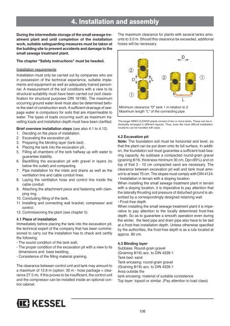
4. Installation and assemblyDuring the intermediate storage of the small sewage treatmentplant and until completion of the installationwork, suitable safeguarding measures must be taken atthe building site to prevent accidents and damage to thesmall sewage treatment plant.The maximum clearance for plants with several tanks amountsto 3.0 m. Should this clearance be exceeded, additionalhoses will be necessary.The chapter "Safety instructions" must be heeded.Installation requirementsInstallation must only be carried out by companies who arein possession of the technical experience, suitable implementsand equipment as well as adequately trained personnel.A measurement of the soil conditions with a view to itsstructural suitability must have been carried out (soil classificationfor structural purposes DIN 18196). The maximumoccurring ground water level must also be determined beforethe start of construction work. A sufficient drainage of seepagewater is compulsory for soils that are impermeable towater. The types of loads occurring such as maximum travellingloads and installation depth must have been clarified.Brief overview installation steps (see also 4.1 to 4.12)1. Deciding on the place of installation.2. Excavating the excavation pit.3. Preparing the blinding layer (tank bed) .4. Placing the tank into the excavation pit..5. Filling all chambers of the tank halfway up with water toguarantee stability.6. Backfilling the excavation pit with gravel in layers (tobelow the outlet) and compacting.7. Pipe installation for the inlets and drains as well as theventilation line and cable conduit lines.8. Laying the ventilation hose and control line inside thecable conduit.9. Attaching the attachment piece and fastening with clampingring.10. Concluding filling of the tank.11. Installing and connecting wall bracket, compressor andcontrol.12. Commissioning the plant (see chapter 5).4.1 Place of installationImmediately before placing the tank into the excavation pit,the technical expert of the company that has been commissionedto carry out the installation has to check and certifythe following:- The sound condition of the tank wall;- The proper condition of the excavation pit with a view to itsdimensions and base bedding;- Consistence of the filling material graining.The clearance between control unit and tank may amount toa maximum of 12.6 m (option: 30 m - hose package = clearance27.5 m). If this proves to be insufficient, the control unitand the compressor can be installed inside an optional controlcabinet.➁➀➁Minimum clearance "D" tank 1 in relation to 2Maximum length "L" of the connecting pipe➀The larger INNO-CLEAN® plants consist of two or more tanks. These can be individuallyarranged in different layouts. Thus, even the most difficult installationlocations can be handled with ease.4.2 Excavation pitNote: The foundation soil must be horizontal and level, sothat the plant can be put down onto its full surface. In addition,the foundation soil must guarantee a sufficient load bearingcapacity. As subbase a compacted round-grain gravel(graining 8/16, thickness minimum 30 cm, Dpr=95%) and ontop of that 3 - 10 cm compacted sand are necessary. Theclearance between excavation pit wall and tank must amountto at least 70 cm. The slopes must comply with DIN 4124.• Installation in terrain with a sloping locationWhen installing the small sewage treatment plant in terrainwith a sloping location, it is imperative to pay attention thatthe laterally thrusting soil pressure of disturbed ground is absorbedby a correspondingly designed retaining wall.• Frost-free depthWhen installing the small sewage treatment plant it is imperativeto pay attention to the locally determined frost-freedepth. So as to guarantee a smooth operation even duringthe winter, the feed pipe and drain pipe also have to be laidat a frost-free installation depth. Unless otherwise specifiedby the authorities, the frost-free depth is as a rule located atapprox. 80 cm.4.3 Blinding layerSubbase: Round-grain gravel(Graining 8/16) acc. to DIN 4226-1Tank bed: sandTank encasing: round-grain gravel(Graining 8/16) acc. to DIN 4226-1Area outside thetank encasing: material of suitable consistenceTop layer: topsoil or similar. (Pay attention to load class)106
4. Installation and assembly≤ 20cm≤ 30cm≤ 30cm≤ 30cm≥ 50cm≥ 50cm≤ 30cm≤ 30cm≤ 30cm≤ 30cm≤ 30cmβ nachDIN 4124≤ 30cm3-10cm≥ 30cm≥ 70cm Subbase: round-grain gravel (max. graining 8/16) accordingto DIN 4226-1 compacted with Dpr=95% Tank bed: compacted sand Tank Tank encasing: round-grain gravel (max. graining 8/16)≥ 70cmaccording to DIN 4226-1 compacted with Dpr=95%Area outside tank encasing: material of suitableconsistenceTop layer: topsoil, road surface, concrete or similar4.4 PlacingThe tank must be placed shock-free into the excavation pitwith the aid of suitable equipment and put down onto thebase bedding (see also chapter "Transport").Pay attention to direction of flow and direction of flow arrowson the tank!4.5 Filling the tankFill tanks in both chambers with clear water (approx. 80 cm)to achieve an improved stability.4.6 Backfilling the excavation pitIn general, filling the tank and backfilling the excavation pitshould be carried out in parallel. The excavation pit is backfilledup to the bottom edge of inlet and drain, as well as theventilation line and cable conduit line. The tank encasingmust be produced in a width of at least 50 cm. The individuallayers of the backfilling material should not exceed a heightof 30 cm. They must be compacted using light compactingequipment (minimum Dpr=95%). Damage to the tank walland a dislocation of the tanks during and after installationmust be ruled out.4.7 PipeworkA Pipe installation example is available on pages 224-227.Theinlet/drain lines as well as connecting lines must be laid in afrost-free manner (see 4.2) and connected as soon as the excavationpit has been backfilled and compacted up to the bottomedge of inlet and drain line.The transition from penstocks to horizontal lines must beexecuted with two 45° curved fittings and an at least 250 mmlong connecting piece. A stilling section, the length of whichcorresponds to at least the tenfold of the pipeline's nominalwidth, must be provided upstream of the INNO-CLEAN ®tank.A cable conduit (KG pipe made of PVC-U in the dimensionDN 100) must be laid as line link between control unit/ compressorand valve block /INNO-CLEAN ® tank. The emptyconduit should exhibit a constant gradient of ≥ 2° in relationto the tank along its entire length. KESSEL recommends toexecute the duct through the building wall in the manner ofwall ducts customary in trade (see illustration).In order to seal the cable conduit inside the building theKESSEL cover (cable conduit sealing, item No. 97711)107
- Page 56 and 57: 2. GénéralitésConfiguration des
- Page 58 and 59: 2. GénéralitésConfiguration des
- Page 60 and 61: 2. Généralités4. Phase de décan
- Page 62 and 63: 4. Installation et montagePendant l
- Page 64 and 65: 4. Installation et montageDalle en
- Page 66 and 67: 4. Installation et montageLes lange
- Page 68 and 69: 4. Installation et montageMontage e
- Page 70 and 71: 5. Mise en service écran / champ d
- Page 72 and 73: 6. Entretien et vidange de boueCett
- Page 74 and 75: 6. Entretien et vidange de boue6.4
- Page 76 and 77: 7. Maintenance7.2 Maintenance du co
- Page 78 and 79: 8. Programmation de la micro statio
- Page 80 and 81: 8. Programmation de la micro statio
- Page 82 and 83: 9. Pannes - solutionsDéfaut Raison
- Page 84 and 85: 10. Garantie1. Si une livraison ou
- Page 86 and 87: 12. Certificat de conformité86
- Page 88 and 89: 14. Piéces détachée d´INNO-CLEA
- Page 90 and 91: 16. Information techniqueAppareil d
- Page 92 and 93: INSTALLATION, OPERATING AND MAINTEN
- Page 94 and 95: Table of contents1. Safety instruct
- Page 96 and 97: 2. General2.1 Area of applicationII
- Page 98 and 99: 2. General2.4 Dimensions and useful
- Page 100 and 101: 2. GeneralPlant configuration EW 12
- Page 102 and 103: 2. GeneralPlant configuration EW 32
- Page 104 and 105: 2. General4. Sedimentation phaseThe
- Page 108 and 109: 4. Installation and assemblyConcret
- Page 110 and 111: 4. Installation and assemblyThe sea
- Page 112 and 113: 4. Installation and assemblyAssembl
- Page 114 and 115: 5. Commissioning Display/indicator
- Page 116 and 117: 6. Operation and disposalAs soon as
- Page 118 and 119: 6. Operation and disposal6.4 Dispos
- Page 120 and 121: 7. Maintenance7.2 Compressor mainte
- Page 122 and 123: 8. Control of the septic system8. C
- Page 124 and 125: 8. Control of the septic system8.3.
- Page 126 and 127: 9. Malfunctions and remedial measur
- Page 128 and 129: 10. Warranty1. In the case that a K
- Page 130 and 131: 12. EC Declaration of conformity130
- Page 132 and 133: 14. Maintenance ChecklistMaster dat
- Page 134 and 135: 16. Spare Parts134
- Page 136 and 137: INSTRUKCJA ZABUDOWY, OBSŁUGI I KON
- Page 138 and 139: Spis treści1. Wskazówki dotycząc
- Page 140 and 141: 2. Informacje ogólne2.1 Zakres zas
- Page 142 and 143: 2.4 Wymiary i pojemność użytkowa
- Page 144 and 145: Konfiguracja urządzenia EW 12, EW
- Page 146 and 147: 2. Informacje ogólneKonfiguracja u
- Page 148 and 149: 2. Informacje ogólne4. Faza osadza
- Page 150 and 151: 4. Zabudowa i montażPodczas skład
- Page 152 and 153: 4. Zabudowa i montażStrop betonowy
- Page 154 and 155: 4. Zabudowa i montażWarga uszczelk
<strong>4.</strong> <strong>Installation</strong> and assemblyDuring the intermediate storage of the small sewage treatmentplant and until compl<strong>et</strong>ion of the installationwork, suitable safeguarding measures must be taken atthe building site to prevent accidents and damage to thesmall sewage treatment plant.The maximum clearance for plants with several tanks amountsto 3.0 m. Should this clearance be exceeded, additionalhoses will be necessary.The chapter "Saf<strong>et</strong>y instructions" must be heeded.<strong>Installation</strong> requirements<strong>Installation</strong> must only be carried out by companies who arein possession of the technical experience, suitable implementsand equipment as well as adequately trained personnel.A measurement of the soil conditions with a view to itsstructural suitability must have been carried out (soil classificationfor structural purposes DIN 18196). The maximumoccurring ground water level must also be d<strong>et</strong>ermined befor<strong>et</strong>he start of construction work. A sufficient drainage of seepagewater is compulsory for soils that are impermeable towater. The types of loads occurring such as maximum travellingloads and installation depth must have been clarified.Brief overview installation steps (see also <strong>4.</strong>1 to <strong>4.</strong>12)1. Deciding on the place of installation.2. Excavating the excavation pit.3. Preparing the blinding layer (tank bed) .<strong>4.</strong> Placing the tank into the excavation pit..5. Filling all chambers of the tank halfway up with water toguarantee stability.6. Backfilling the excavation pit with gravel in layers (tobelow the outl<strong>et</strong>) and compacting.7. Pipe installation for the inl<strong>et</strong>s and drains as well as theventilation line and cable conduit lines.8. Laying the ventilation hose and control line inside thecable conduit.9. Attaching the attachment piece and fastening with clampingring.10. Concluding filling of the tank.11. Installing and connecting wall brack<strong>et</strong>, compressor andcontrol.12. Commissioning the plant (see chapter 5).<strong>4.</strong>1 Place of installationImmediately before placing the tank into the excavation pit,the technical expert of the company that has been commissionedto carry out the installation has to check and certifythe following:- The sound condition of the tank wall;- The proper condition of the excavation pit with a view to itsdimensions and base bedding;- Consistence of the filling material graining.The clearance b<strong>et</strong>ween control unit and tank may amount toa maximum of 12.6 m (option: 30 m - hose package = clearance27.5 m). If this proves to be insufficient, the control unitand the compressor can be installed inside an optional controlcabin<strong>et</strong>.➁➀➁Minimum clearance "D" tank 1 in relation to 2Maximum length "L" of the connecting pipe➀The larger INNO-CLEAN® plants consist of two or more tanks. These can be individuallyarranged in different layouts. Thus, even the most difficult installationlocations can be handled with ease.<strong>4.</strong>2 Excavation pitNote: The foundation soil must be horizontal and level, sothat the plant can be put down onto its full surface. In addition,the foundation soil must guarantee a sufficient load bearingcapacity. As subbase a compacted round-grain gravel(graining 8/16, thickness minimum 30 cm, Dpr=95%) and ontop of that 3 - 10 cm compacted sand are necessary. Theclearance b<strong>et</strong>ween excavation pit wall and tank must amountto at least 70 cm. The slopes must comply with DIN 412<strong>4.</strong>• <strong>Installation</strong> in terrain with a sloping locationWhen installing the small sewage treatment plant in terrainwith a sloping location, it is imperative to pay attention thatthe laterally thrusting soil pressure of disturbed ground is absorbedby a correspondingly designed r<strong>et</strong>aining wall.• Frost-free depthWhen installing the small sewage treatment plant it is imperativ<strong>et</strong>o pay attention to the locally d<strong>et</strong>ermined frost-freedepth. So as to guarantee a smooth operation even duringthe winter, the feed pipe and drain pipe also have to be laidat a frost-free installation depth. Unless otherwise specifiedby the authorities, the frost-free depth is as a rule located atapprox. 80 cm.<strong>4.</strong>3 Blinding layerSubbase: Round-grain gravel(Graining 8/16) acc. to DIN 4226-1Tank bed: sandTank encasing: round-grain gravel(Graining 8/16) acc. to DIN 4226-1Area outside th<strong>et</strong>ank encasing: material of suitable consistenceTop layer: topsoil or similar. (Pay attention to load class)106


