4. Installation et montage - Kessel
4. Installation et montage - Kessel
4. Installation et montage - Kessel

You also want an ePaper? Increase the reach of your titles
YUMPU automatically turns print PDFs into web optimized ePapers that Google loves.
2. Allgemeines2.3 AnlagenkonfigurationSeitenansichtBehälter EW 4 - 6Nutzvolumen 4800 lh2 Th leerT EÜh1LSeitenansichtBehälter EW 8 -10Nutzvolumen 7600 lLFrontansichtGWB7
2. Allgemeines2.4 Maße und NutzvolumenEinwohnergleichwert(EW)maximalerSchmutzwasserzulauf(l/Tag)ArtikelnummerReinigungsklasseC DAnzahlBehälterZu-/Ablauf(DN)Gesamtvolumen(l)Länge Länge (L)(mm)Breite Breite (B)(mm)Tiefe Tiefe (T)GOK bis Sohle Zulauf(mm)(mm)T EÜ(mm)Grundwasser(GW) (mm)(mm)HöheZulauf Zulauf (h2)(mm)(mm)HöheAuslaufAuslauf(h1)(mm)(mm)HöheKabelleerrohr(hleer)Kabelleerrohr(mm)Gewicht(ca. kg)Gesamt Behälter 1 Behälter 2 Behälter 3 Behälter 4 Behälter 5 Behälter 6 L 1 L 2 L 3 b1=b2 min max4 600 97804 RC 97804 RD 1 150 4800 4800 2350 2000 604 1054 T-255 1775 1875 1775 2000 5306 900 97806 RC 97806 RD 1 150 4800 4800 2350 2000 604 1054 T-255 1775 1875 1775 2000 5308 1.200 97808 RC 97808 RD 1 150 7600 7600 3470 2000 604 1054 T-255 1775 1875 1775 2000 70010 1.500 97810 RC 97810 RD 1 150 7600 7600 3470 2000 604 1054 T-255 1775 1875 1775 2000 70012 1.800 97812 RC 97812 RD 2 150 9600 4800 4800 2350 2350 2000 604 1054 T-255 1775 1875 1775 2000 97014 2.100 97814 RC 97814 RD 2 150 12400 7600 4800 3470 2350 2000 604 1054 T-255 1775 1875 1775 2000 113016 2.400 97816 RC 97816 RD 2 150 12400 7600 4800 3470 2350 2000 604 1054 T-255 1775 1875 1775 2000 113018 2.700 97818 RC 97818 RD 2 150 15200 7600 7600 3470 3470 2000 604 1054 T-255 1775 1875 1775 2000 130020 3.000 97820 RC 97820 RD 2 150 15200 7600 7600 3470 3470 2000 604 1054 T-255 1775 1875 1775 2000 130022 3.300 97822 RC 97822 RD 3 150 18300 5350 7600 5350 2350 3470 2350 2000 604 1054 T-255 1775 1875 1775 2000 143024 3.600 97824 RC 97824 RD 3 150 21000 8100 4800 8100 3470 2350 3470 2000 604 1054 T-255 1775 1875 1775 2000 154026 3.900 97826 RC 97826 RD 3 150 21000 8100 4800 8100 3470 2350 3470 2000 604 1054 T-255 1775 1875 1775 2000 154028 <strong>4.</strong>200 97828 RC 97828 RD 3 150 23800 8100 7600 8100 3470 3470 3470 2000 604 1054 T-255 1775 1875 1775 2000 170030 <strong>4.</strong>500 97830 RC 97830 RD 3 150 23800 8100 7600 8100 3470 3470 3470 2000 604 1054 T-255 1775 1875 1775 2000 170032 <strong>4.</strong>800 97832 RC 97832 RD 6 150 31000 5350 5350 4800 5350 4800 5350 2350 2350 2350 2000 604 1054 T-255 1775 1875 1775 2000 262034 5.100 97834 RC 97834 RD 6 150 31000 5350 5350 4800 5350 4800 5350 2350 2350 2350 2000 604 1054 T-255 1775 1875 1775 2000 262036 5.400 97836 RC 97836 RD 6 150 31000 5350 5350 4800 5350 4800 5350 2350 2350 2350 2000 604 1054 T-255 1775 1875 1775 2000 262038 5.700 97838 RC 97838 RD 6 150 36600 5350 5350 7600 5350 7600 5350 2350 3470 2350 2000 604 1054 T-255 1775 1875 1775 2000 295040 6.000 97840 RC 97840 RD 6 150 36600 5350 5350 7600 5350 7600 5350 2350 3470 2350 2000 604 1054 T-255 1775 1875 1775 2000 295042 6.300 97842 RC 97842 RD 6 150 36600 5350 5350 7600 5350 7600 5350 2350 3470 2350 2000 604 1054 T-255 1775 1875 1775 2000 295044 6.600 97844 RC 97844 RD 6 150 36600 5350 5350 7600 5350 7600 5350 2350 3470 2350 2000 604 1054 T-255 1775 1875 1775 2000 295046 6.900 97846 RC 97846 RD 6 150 42000 8100 8100 4800 8100 4800 8100 3470 2350 3470 2000 604 1054 T-255 1775 1875 1775 2000 315048 7.200 97848 RC 97848 RD 6 150 42000 8100 8100 4800 8100 4800 8100 3470 2350 3470 2000 604 1054 T-255 1775 1875 1775 2000 315050 7.500 97850 RC 97850 RD 6 150 42000 8100 8100 4800 8100 4800 8100 3470 2350 3470 2000 604 1054 T-255 1775 1875 1775 2000 3150Bitte beachten Sie:witterungsbedingte Einflüsse oder Abkühlung während der Verbauphase (durch Befüllen mit kaltem Wasser),können bei den Behältern zu Abweichungen von den Maßangaben führen.Bitte prüfen Sie daher vor Verbau insbesondere die Höhenangaben auf ihr tatsächliches Maß.8
Anlagenkonfiguration EW 4, EW 6, EW 8 und EW 102. Allgemeines9
2. AllgemeinesAnlagenkonfiguration EW 12, EW 14, EW 16 und EW 2010
2. AllgemeinesAnlagenkonfiguration EW 22 bis EW 3011
2. AllgemeinesAnlagenkonfiguration EW 32 bis EW 5012
2. Allgemeines2.5 FunktionsbeschreibungDer Klärprozess wird vollautomatisch vonder Steuereinheit geregelt. Ein Klärzyklusdauert ca. 8 Stunden und wird durchAbführen des geklärten Wassers beend<strong>et</strong>.Der Klärungsprozess basiert auf Mikroorganismen,die während der Behandlungsphasedas Abwasser reinigen.1. Einleitung des Schwarzwassers(gesamtes häusliches Abwasser)Sämtliches häusliches Abwasser gelangt indie Vorklärkammer. Dort sinken dieSchwerteile zum Boden ab und bilden eineSchlammschicht. Der Abwasserschlammverbleibt in der Vorklärkammer, verdicht<strong>et</strong>sich und muss bei Erreichen der maximalenAufnahmekapazität entsorgt werden.2. Füllen der Belebungskammer(Beschickung)Die Belebungskammer wird mit dem Abwasseraus der Vorklärkammer befüllt.Über den Beschickungsheber wird ein definiertesAbwasservolumen aus der Vorklärkammerin die Belebungskammer geführt.3. Behandlungsphase des Abwassers(Normal-, Spar- und Urlaubsphase)In der Belebungskammer wird das Abwassermit kurzen Belüfterstößen (Membranrohrbelüfter)verwirbelt. Durch eine phasenweiseBelüftung gelangt Sauerstoff indas Abwasser und Mikroorganismen erhaltenSauerstoff für den Nährstoffabbau.Dabei bild<strong>et</strong> sich Belebtschlamm. Der Stoffwechselder Mikroorganismen reinigt dasAbwasser.Die Behandlungsphase dauert in der Regelca. sechs Stunden. Darüber hinaus reguliertsich die Anlage gemäß ihrer Beschickung.Die Abwasserbehandlung läuftdann im Rahmen der “Normalphase”, der“Sparphase” oder der “Urlaubsphase” ab.(siehe Punkt 6.1)13
3. Verpackung, Transport und LagerungDas Kapitel Sicherheitshinweise ist zu beachten!3.1 VerpackungEine Verpackung der Behälter zum Zwecke des Transportsbzw. der Lagerung ist bei Beachtung der nachfolgendenPunkte nicht notwendig.Hinweis: Der Eintrag von Fremdkörpern (Schmutz, Staub<strong>et</strong>c.) während der Verbauphase in die Kläranlage ist zu vermeiden.Ggf. sind an allen Öffnungen Abdeckungen anzubringen.3.2 Transport• Der Transport ist nur von solchen Firmen durchzuführen,die über fachliche Erfahrungen, geeign<strong>et</strong>e Geräte, Einrichtungenund Transportmittel, sowie ausreichend geschultesPersonal verfügen.• Die Behälter müssen so transportiert werden, daß sie nichtunzulässig belast<strong>et</strong> werden und dass eine Lageveränderungwährend des Transports ausgeschlossen ist. Im Falleeiner Verspannung ist diese so vorzunehmen, dass eineBeschädigung der Behälter ausgeschlossen ist (z.B. Verwendungvon Gewebe- oder Schlaufengurten). Die Verwendungvon Drahtseilen oder K<strong>et</strong>ten ist nicht zulässig.• Die Behälter sind gegen unzulässige Lageveränderungenwährend der Beförderung zu sichern. Durch die Art der Befestigungdürfen die Behälter nicht beschädigt werden.3.3 LagerungSollte eine Lagerung der Behälter vor dem Einbau erforderlichsein, so darf diese nur kurzzeitig und auf ebenem, vonscharfkantigen Gegenständen befreitem Untergrund geschehen.Bei Lagerung im Freien sind die Behälter gegenBeschädigung, Sturmeinwirkung und Verschmutzung zuschützen.• Beim Abheben, Verfahren und Abs<strong>et</strong>zen der Behälter müssenstoßartige Beanspruchungen vermieden werden.Kommt ein Gabelstapler zum Einsatz, müssen während derFahrt mit dem Gabelstapler die Behälter gesichert werden.Ein Rollen oder Schleifen der Behälter über den Untergrundist nicht zulässig. Auf der Ladefläche eines LKW darfder Behälter für Zwecke der Be- und Entladung geschobenund gezogen werden.15
<strong>4.</strong> Einbau und MontageWährend der Zwischenlagerung der Kleinkläranlagesowie bis zum Abschluss der Einbauarbeiten, müssenan der Baustelle geeign<strong>et</strong>e Sicherungsmaßnahmen g<strong>et</strong>roffenwerden, um Unfälle und Beschädigungen derKleinkläranlage zu verhindern.Das Kapitel Sicherheitshinweise ist zu beachten.Einbauvorauss<strong>et</strong>zungenDer Einbau ist nur von solchen Firmen durchzuführen, dieüber fachliche Erfahrungen, geeign<strong>et</strong>e Geräte und Einrichtungensowie ausreichend geschultes Personal verfügen.Eine Erfassung der Bodenbeschaffenheit im Hinblick auf diebautechnische Eignung muss vorgenommen worden sein(Bodenklassifikation für bautechnische Zwecke DIN 18196).Der maximal auftr<strong>et</strong>ende Grundwasserstand muss ebensovor Beginn der Bauarbeiten festgestellt werden. Eine ausreichendeAbleitung (Drainage) von Sickerwässern ist beiwasserundurchlässigen Böden zwingend notwendig. Dieauftr<strong>et</strong>enden Belastungsarten wie max. Verkehrslasten undEinbautiefe müssen abgeklärt sein.Kurzübersicht Einbauschritte (siehe auch <strong>4.</strong>1 bis <strong>4.</strong>12)1. Einbauort festlegen.2. Baugrube ausheben.3. Sauberkeitsschicht (Behälterb<strong>et</strong>t) erstellen.<strong>4.</strong> Behälter in die Baugrube eins<strong>et</strong>zen.5. Behälter in allen Kammern bis zur Hälfte mit Wasser befüllen,um Standsicherheit zu gewährleisten.6. Baugrube mit Kies (bis unter den Auslauf) lagenweiseverfüllen und verdichten.7. Verrohrung der Zu- und Abläufe, sowie der Lüftungsleitungund Kabelleerrohrleitung.8. Belüftungsschlauch und Steuerleitung im Kabelleerrohrverlegen.9. Aufsatzstück aufs<strong>et</strong>zen und mit Klemmring fixieren.10. Abschließende Befüllung des Behälters.11. Wandkonsole, Verdichter und Steuerung montieren undanschließen.12. Inb<strong>et</strong>riebnahme der Anlage (siehe Kapitel 5).<strong>4.</strong>1 EinbauortUnmittelbar vor dem Einbringen des Behälters in die Baugrubehat der Sachkundige der mit dem Einbau beauftragtenFirma folgendes zu prüfen und zu bescheinigen:- Die Unversehrtheit der Behälterwand;- den ordnungsgemäßen Zustand der Baugrube, insbesonderehinsichtlich der Abmessungen und Sohlenb<strong>et</strong>tung;- Beschaffenheit der Körnung des Verfüllmaterials.Die Distanz zwischen Steuereinheit und Behälter darf maximal12,5 m (Option: 30 m - Schlauchpak<strong>et</strong> = Distanz 27,5 m)b<strong>et</strong>ragen. Sollte dies nicht ausreichen, so kann die Steuereinheitund der Verdichter in einem optionalen Schaltschrankinstalliert werden.Der max. Abstand bei Anlagen mit mehreren Behältern b<strong>et</strong>rägt3,0 m. Sollten Sie diesen Abstand überschreiten, sosind zusätzliche Schläuche notwendig.<strong>4.</strong>2 Baugrube➁➀➁➀Die größeren INNO-CLEAN + -Anlagen bestehen aus zwei oder mehr Behältern.Diese lassen sich individuell in verschiedenen Varianten anordnen. So könnenschwierigste Einbausituationen leicht gemacht werden.Hinweis: Bei Mehrbehälteranlagen eine Baugrube für alleBehälter ausheben!Der Baugrund muss waagerecht und eben sein, um die Anlagevollflächig aufstellen zu können. Außerdem muss derBaugrund eine ausreichende Tragfähigkeit gewährleisten.Als Unterbau ist ein verdicht<strong>et</strong>er Rundkornkies (Körnung8/16, Dicke mind. 30 cm, Dpr=95%) und darauf 3 - 10 cm verdicht<strong>et</strong>erSand notwendig. Der Abstand zwischen Baugrubenwandund Behälter muss mindestens 70 cm b<strong>et</strong>ragen.Die Böschungen müssen der DIN 4124 entsprechen.• Einbau im Gelände mit HanglageBeim Einbau der Kleinkläranlage in ein Gelände mit Hanglageist unbedingt darauf zu achten, dass der seitlich schiebendeErddruck bei nicht gewachsenem Boden durch eineentsprechend ausgelegte Stützmauer abgefangen wird.• Frostfreie TiefeBeachten Sie beim Einbau der Kleinkläranlage unbedingt dieörtlich festgelegte frostfreie Tiefe. Um auch im Winter einenreibungslosen B<strong>et</strong>rieb zu gewährleisten, ist beimEinbau ebenso die Zu- und Ablaufleitung in frostfreierEinbautiefe zu verlegen. In aller Regel liegt die frostfreieTiefe, wenn nicht anders durch die Behörde angegeben, beica. 80 cm.<strong>4.</strong>3 SauberkeitsschichtUnterbau: Rundkornkies(Körnung 8/16) nach DIN 4226-1Behälterb<strong>et</strong>t: SandBehälterumhüllung: Rundkornkies(Körnung 8/16) nach DIN 4226-1Bereich außerhalbBehälterumhüllung: Material geeign<strong>et</strong>er BeschaffenheitDeckschicht: Humus o.ä. (Belastungsklasse beachten)16
<strong>4.</strong> Einbau und Montage≤ 20cm≤ 30cm≤ 30cm≤ 30cm≥ 50cm≥ 50cm≤ 30cm≤ 30cm≤ 30cm≤ 30cm≤ 30cmβ nachDIN 4124≤ 30cm3-10cm≥ 30cm≥ 70cm Unterbau: Rundkornkies (max. Körnung 8/16) nachDIN 4226-1 verdicht<strong>et</strong> mit Dpr=95% Behälterb<strong>et</strong>t: verdicht<strong>et</strong>er Sand Behälter Behälterumhüllung: Rundkornkies (max. Körnung≥ 70cm8/16) nach DIN 4226-1 verdicht<strong>et</strong> mit Dpr=95% Bereich außerhalb Behälterumhüllung:Material geeign<strong>et</strong>er Beschaffenheit Deckschicht: Humus, Straßenbelag, B<strong>et</strong>on o.ä.<strong>4.</strong>4 Eins<strong>et</strong>zenDer Behälter ist mit Hilfe einer geeign<strong>et</strong>en Vorrichtungstoßfrei in die Baugrube einzubringen und auf die Sohlenb<strong>et</strong>tungaufzus<strong>et</strong>zen (siehe auch Kapitel „Transport“).Fließrichtung und Fließrichtungspfeile auf dem Behälter beachten!<strong>4.</strong>5 Behälter befüllenBehälter in beiden Kammern mit Klarwasser befüllen (ca. 80cm) um eine bessere Standfestigkeit zu erlangen.<strong>4.</strong>6 Verfüllung BaugrubeGenerell sollte das Befüllen des Behälters und die Verfüllungder Baugrube parallel ausgeführt werden. Die Verfüllung derBaugrube erfolgt bis Unterkante Zu- und Ablauf, sowie derLüftungs- und Kabelleerrohrleitung. Die Behälterumhüllungmuss in einer Breite von mindestens 50 cm hergestellt werden.Die einzelnen Lagen des Verfüllmaterials sollten nichthöher als 30 cm sein. Sie sind mit leichten Verdichtungsgerätenzu verdichten (mind. Dpr=95%). Eine Beschädigungder Behälterwand und eine Verlagerung der Behälter währendund nach dem Einbau muss ausgeschlossen werden.<strong>4.</strong>7 VerrohrungEinen Vorschlag zur Verlegung der Rohrleitungen finden Sieauf den Seiten 224-227. Die Zu-/Ablaufleitungen, sowie Verbindungsleitungensind frostfrei (siehe <strong>4.</strong>2) zu verlegen undanzuschließen, sobald die Baugrube bis zur Unterkante derZu- und Ablaufleitung verfüllt und verdicht<strong>et</strong> ist.Der Übergang von Fallleitungen in horizontale Leitungen istmit zwei 45°-Bogenformstücken und einem mindestens 250mm langen Zwischenstück auszuführen. Vor dem INNO-CLEAN + -Behälter ist eine Beruhigungsstrecke vorzusehen,deren Länge mindestens dem 10-fachen der Nennweite derRohrleitung entspricht.• KabelleerrohrFür die Leitungsverbindung zwischen Steuergerät/Kompressorund Ventilblock/INNO-CLEAN + -Behälter muss einKabelleerrohr (KG-Rohr aus PVC-U in der Dimension DN100) verlegt werden. Das Leerrohr sollte über seine gesamteLänge über ein st<strong>et</strong>iges Gefälle von ≥ 2° zum Behälter verfügen.Für die Durchführung durch die Gebäudewand empfiehltKESSEL auf handelsübliche Wanddurchführungenzurück zu greifen (siehe Bild). Zur Abdichtung des Kabel-17
<strong>4.</strong> Einbau und MontageB<strong>et</strong>ondeckeKellerwandKabelleerrohrabdichtungArt. Nr. 97 711KG-Rohr DN 100DichtungArt.-Nr. 860116Dichtung fürRohrdurchführungVentilblockInno-CleanhandelsüblicheWanddurchführungz. B. Fa. Steelter oderFa. DOYMA DN 100 Gefälle mind. 2°fallend zum BehälterBehälterwandInno-Cleanleerrohres im Gebäude, sollte die Abdeckung von KESSEL(Kabelleerrohrabdichtung Art.-Nr. 97711) zum Schutz vorGeruchsbelästigungen einges<strong>et</strong>zt werden.Richtungsänderungen sollten über Bogenformstücke mit maximal30° Abwinkelung realisiert werden.<strong>4.</strong>8 Verlegung der Verbindungsleitungen zur Steuereinheit(Belüftungsschlauch und Steuerleitung)Luftschlauch zum VerdichterAchtung: Alle Leitungen sollten temporär bis zum endgültigenAnschluß, mit Klebeband verschlossen werden, umSchmutzeintrag während des Durchschiebens zu vermeiden.SchnellverbinderVentilblockVerriegelungsbügelBemerkung:Die Behälter können im Bereich der Dome angebohrt werden,um zusätzliche Anschluß- und Lüftungsleitungen herzustellen.Hierzu sind Original-Bohrkronen und Rohrdurchführungsdichtungenvon KESSEL zu verwenden (KESSEL-Bohrkronen DN 50 - DN 150, Art.-Nr. 50100,KESSEL-Rohrdurchführungsabdichtungen:DN 50 Art.-Nr. 850114DN 70 Art.-Nr. 850116DN 100 Art.-Nr. 850117DN 125 Art.-Nr. 850118DN 150 Art.-Nr. 850119)Die Bohrungen sollten auf möglichst planen Flächen erfolgen.Für eine optimale Abdichtung der Bohrung sollte derAbstand zwischen dem Rand der Bohrung und unebenerKontur mindestens 15 mm b<strong>et</strong>ragen, damit die Dichtung umlaufendgleichmäßig um die Bohrung anliegt.• EntlüftungDie Be- und Entlüftung der Anlage erfolgt über eine Lüftungsleitungder Größe DN 100 und wird an der entsprechenden Öffnungam Dom angeschlossen. Eine zusätzliche Lüftungsleitungkann am Dom angeschlossen werden (siehe Abb. S. 5).Hierzu ist die entsprechende Bohrkrone und Rohrdurchführungsdichtungvon KESSEL zu verwenden . KESSEL empfiehltdie Verwendung eines Aktivkohlefilters zur Vermeidungvon Geruchsbelästigung.AdapterplatteLasche zumEinhängen derSteuerleitungSteuerleitungLuftschläuche zu den DrucklufthebernDie Steuerleitung, sowie der Belüftungsschlauch sind zwischenVentilblock und Steuereinheit im Kabelleerrohr zu verlegen( siehe Vorgehen).Vorgehen:- Öffnen des Verriegelungsbügels am Ventilblock im Behälter- Entnahme des Ventilblocks von der Adapterplatte- grauen Belüftungsschlauch und Steuerleitung durch dasKabelleerrohr ziehen- Belüftungsschlauch mittels Schnellverbinder am Ventilblockanschließen (siehe <strong>4.</strong>11 Punkt 5)- Ventilblock auf Adapterplatte eins<strong>et</strong>zen- Achtung: Steuerleitung muss in vorgesehene Lasche eingeklipstwerden (siehe Abb.) um ein korrektes Verriegelnmit der Adapterplatte zu gewährleisten.- Ventilblock auf korrekten Sitz prüfen und Verriegelungsbügelschließen18
<strong>4.</strong> Einbau und Montage<strong>4.</strong>9 Montage der AufsatzstückeZuerst die Dichtung (siehe Zeichnung <strong>4.</strong>9) in die vorgeseheneSicke im Dom einlegen.Das teleskopische KESSEL-Aufsatzstück im unteren Bereichmit Gleitmittel einf<strong>et</strong>ten und in die Behälteröffnung einstecken,in die gewünschte Position bringen und mittelsKlemmring fixieren. Alternativ kann Gleitmittel auch auf denDichtring aufg<strong>et</strong>ragen werden. Mit Hilfe des vorhandenenKlemmringes kann nun das Aufsatzstück in der gewünschtenPosition (Ausrichtung an der Geländeoberkante) fixiertwerden. Die Feinjustierung auf die endgültige Höhe erfolgtdann mittels der Stellschrauben. Bodenneigungen könnendurch das stufenlos höhenverstellbare und bis 5° neigbareAufsatzstück ausgeglichen werden. Die mitgelieferten Aufkleberder “Innofanten” sind auf die gereinigte und trockeneInnenfläche am Aufsatzstück anzubringen (siehe Bild).Wichtig: Der grüne “Innofant” ist auf die Zulaufseite zu klebenund der rote auf die Auslaufseite!Anschließend das Aufsatzstück ausreichend verfüllen undverdichten.19
<strong>4.</strong> Einbau und MontageDie Dichtlippe soll auf der Innenseite desRinges nach unten zeigen.Zulauf➔➔Auslauf<strong>4.</strong>10 Abschließende Befüllung des BehältersVor dem Verfüllen nochmaliges Kontrollieren der Zu- und Ablaufleitung, sowie der Entlüftungsleitung und des Kabelleerrohrs.Das Aufsatzstück mit der Geländeoberkante abgleichen.20
<strong>4.</strong> Einbau und Montage N<strong>et</strong>zanschluss Verdichter Wandkonsole Steuergerät N<strong>et</strong>zanschluss Verdichter Anschlussbuchse für potentialfreien Kontakt Anschluss Ventilblock(inkl. Schwimmerschalter) Anschluss externer Signalgeber Druckluftanschluss Ventilblock Anschluss Druckluftsensor Winkelstück fürAnschluss Druckluftschlauch Schnellverbinder<strong>4.</strong> 11 Einbau der Steuereinheit und des VerdichtersBeachten Sie bitte, daß für die Anschlussleitungen vomBehälter zur Steuereinheit ein Kabelleerrohr (DN 100) verlegtwerden muss (siehe <strong>4.</strong>7).Allgemeine HinweiseACHTUNG: KESSEL empfiehlt, für die Ausführung vonelektrischen Anschlüssen, einen Fachb<strong>et</strong>rieb des Elektrohandwerkszu beauftragen. Nehmen sie die Anlageerst nach vollständigem Einbau in B<strong>et</strong>rieb. Während derAnschlussarbeiten darf die Anlage nicht ans N<strong>et</strong>z angeschlossensein.Steuerung und Verdichter sind in einem frostgeschützten,überflutungssicheren und trockenen Raum zu montieren.Rückstausichere Montage beachten!Auf eine gute Belüftung des Raumes in dem der Verdichteraufgestellt wird ist zu achten. Eine ausreichende Luftzirkulation,insbesondere auch bei Geräten die innerhalb einesAußenschaltschrankes untergebracht werden sollen, ist zuachten, um den Verdichter vor Überhitzung zu schützen.Eine kühle Umgebungstemperatur sichert eine hohe Lebensdauerder Membranen und Ventile.Der Verdichter sollte nicht in staubiger Umgebung b<strong>et</strong>riebenwerden. Ein Überhitzen durch verstopfte Filter verkürzt dieLebensdauer der Membranen und Filter.Der Verdichter soll vor direkter Sonneneinstrahlung, Regen,Schnee und Frost geschützt sein. Die angesaugte Umgebungsluftmuss frei von entflammbaren oder aggressivenGasen oder Dämpfen sein.Die Schlauchleitung ist so kurz und so gerade wie möglichzwischen Steuerung und Behälter zu verlegen. Richtungsänderungensind über lange Bögen anstatt engen Abwinkelungenzu realisieren.Der Verdichter ist oberhalb der Steuerung auf einem geeign<strong>et</strong>enSockel oder einer Konsole zu platzieren, um evtl.Schäden zu vermeiden.Bei der Montage auf einer instabilen Unterlage können durchVibrationen störende Geräusche auftr<strong>et</strong>en.Der Verdichter ist horizontal zu montieren, um eine einseitigeBelastung der Membranen und dadurch verkürzte Lebensdauerder Komponenten zu verhindern.Der Verdichter soll auf allen 4 Gummifüßen kompl<strong>et</strong>t aufstehenund soll nicht wackeln.21
<strong>4.</strong> Einbau und MontageMontage und Anschluß Die Wandkonsole ist mittels beider mitgelieferterDübel und Schrauben waagerecht an der Wand zufixieren. Das Steuergerät durch Lösen der vier stirnseitigenKreuzschlitzschrauben öffnen und dessen Rückwandmit den mitgelieferten vier Kreuzschlitzschrauben anden vorgebohrten Stellen der Wandkonsole (unterhalbder Abstellfläche für den Verdichter) befestigen.Anschließend ist der Gehäusedeckel mit max. 1 Nmwieder zu verschrauben. Achtung: Darauf achten,dass das Gerät spannungsfrei ist (siehe SicherheitshinweiseS.2) Den Verdichter auf der Abstellfläche der Wandkonsolein die dafür vorgesehenen Vertiefungen stellen.Bitte beachten Sie, dass die Kontrolllampe nachvorne gericht<strong>et</strong> und der elektrische Anschluss desGerätes auf der rechten Seite des Gerätes ist. DerN<strong>et</strong>zstecker des Verdichters ist mit der Schuko-Kupplungam Schaltgerät zu verbinden. Bevor das Winkelstück für den Anschluss der Druckluftleitungan den Verdichter am Gerät angeschlossenwird, ist die mitgelieferte M<strong>et</strong>allhülse in den langenSchenkel des Winkelstückes einzuschieben. Anschließenderfolgt die Montage des Winkelstückesam Stutzen des Verdichters und dessen Fixierungmittels der Federklemme am Gerät.Abweichung bei den Verdichtergrößen EL 150/200/250: Entfernen Sie den Stutzen beim Verdichter undSchrauben Sie das mitgelieferte Winkelstück am Gewindedes Verdichters ein (Gewinde mit Teflonbando.ä. abdichten). Das Einbringen der M<strong>et</strong>allhülse entfälltbei diesen Verdichtergrößen. Den Schnellverbinder durch Drehen der Verschlusskappe um 60° nach links öffnen und das lange Ende desWinkelstückes bis zum Anschlag einschieben. Die Verschlusskappe durch Rechtsdrehung schließen. Der transparente Schlauch des Druckluftsensors ist mit dem Steuergerät an der dritten Buchse von links anzuschließen.Hierfür die schwarze Überwurfmutter lösen und den innenliegenden Klemmring entnehmen, danachdie Überwurfmutter und den Klemmring auf den transparenten Schlauch aufschieben, anschl. Schlauchaufstecken. Zum Schluss schwarze Überwurfmutter handfest anschrauben. Für den Anschluss der Druckluftleitung aus dem Behälter ist der graue Belüftungsschlauch im Kabelleerrohrauf passende Länge zu kürzen und ohne Abwinkelungen mit dem Schnellverbinder am Verdichter zu fixieren.Achtung: Belüftungsschlauch locker, nicht auf Spannung verlegen. Das Anschlusskabel vom Ventilblock ist in die entsprechende Buchse am Steuergerät einzustecken und mitder Verschraubung zu fixieren.22
<strong>4.</strong> Einbau und MontageOptionale Anschlüsse am Schaltgerät:Achtung: Alle optionalen Anschlüsse sind nur durch Elektrofachkräfte durchzuführen.23
5. Inb<strong>et</strong>riebnahme Display/Anzeigenfeld Bewegungstasten/Richtungstastenfür die Führung durch das Programm-Menü Bestätigungstaste/OK-Taste Zurücktaste/ESC-Taste Kontrolllampe für B<strong>et</strong>riebsbereitschaft Kontrolllampe für Störungsmeldung N<strong>et</strong>zabschlusskabel N<strong>et</strong>zanschluss für Verdichter Anschluss Druckluftsensor Anschlussmöglichkeitenfür externen Signalgeber Anschlus für Ventilblock Anschlussbuchse für potentialfreien KontaktEinweisung / ÜbergabeDas Kapitel Sicherheitshinweise ist zu beachten! (S.2)Hinweis: Die N<strong>et</strong>zleitung muss mit einem FI-Schutzautomatenausgerüst<strong>et</strong> sein.Die Inb<strong>et</strong>riebnahme wird von einem Fachb<strong>et</strong>rieb oder einemKESSEL-Beauftragten durchgeführt (gegen Aufpreis).Folgende Personen sollten bei der Übergabe anwesend sein:- Abnahmeberechtigter des Bauherrn- Fachb<strong>et</strong>riebFerner empfehlen wir die Teilnahme des Bedienungspersonals/B<strong>et</strong>reibers, Entsorgungsunternehmens0.SystemstartSystemdiagnose0.1 SprachedeutschfranzösischenglischÜbersicht Einweisung:5. 1. Anlage in B<strong>et</strong>riebsbereitschaft s<strong>et</strong>zen5. 2. Kontrolle der Anlage5. 3. Einweisung anhand der Einbau- und Bedienungsanleitung5. <strong>4.</strong> Erstellung des Übergabeprotokolls. (siehe Kapitel 13)0.2 Datum/Uhrzeit0.3 KlassenCDDatum01.01.2009 Uhrzeit12:00Nach Beendigung der Einweisung ist die Anlage in b<strong>et</strong>riebsbereitenZustand zu s<strong>et</strong>zen.5.1 Anlage in B<strong>et</strong>riebsbereitschaft s<strong>et</strong>zenDie Anlage ist vor Inb<strong>et</strong>riebnahme vollständig zu reinigen(einschließlich Zu- und Abläufe); Fest- und Grobstoffe sind zuentfernen.Die Anlage ist bis zu einer Höhe von 1,20 m in beiden Kammernmit klarem Wasser zu befüllen. N<strong>et</strong>zstecker des Steuergerätesin die Steckdose stecken. Die Anlage initialisiert sich selbständig.1.5 SysteminfoUhrzeit: 20:45Schwimmer: S1S2Ereignisse:N<strong>et</strong>zausfallNormalphase0.4 NenngrößenEW4EW6EW8EW10…EW2424
5. Inb<strong>et</strong>riebnahmeBei der Erstinitialisierung der Anlage fragt das Steuergerätnach vier Grundeinstellungen. Im Display desSteuergerätes erscheint die Frage nach:1. der Sprache für die Benutzerführung2. dem Datum und der Uhrzeit3. der gewünschten Reinigungsklasse C oder D<strong>4.</strong> der erforderlichen Nenngröße der Anlage.Durch B<strong>et</strong>ätigen der Bewegungstasten / Richtungstastenkann die gewünschte Einstellung über einen Markierungsbalkengekennzeichn<strong>et</strong> werden und die AnschließendeB<strong>et</strong>ätigung der Bestätigungstaste hinterlegt die gewählteEinstellung im Systemspeicher. Sobald die 4 Voreinstellungenvorgenommen wurden, lädt das Steuergerät den Programmspeicherund geht selbständig in den B<strong>et</strong>riebsmodus.Die Anlage ist j<strong>et</strong>zt b<strong>et</strong>riebsbereit.Hinweise zur Schlammrückführung:Die Belebtschlammrückführung ist erforderlich, um dieBildung einer zu großen Menge an Belebtschlamm zu vermeiden.Eine zu große Menge an Belebtschlamm könntezu Störungen im Auslauf der Kläranlage führen und eventuellvorhandene Versickerungsanlagen beeinträchtigen.Die rückgeführte Schlammmenge sedimentiert in der Vorklärkammerund wird mit der nächsten Primärschlammentsorgungabgeführt.Die Steuerung der Schlammrückführung kann über dieZeiten T20 & T21 eingestellt werden. Nach der Inb<strong>et</strong>riebnahmeder Anlage sollten beide Schlammrückführungenfür die ersten 3 bis 5 Monate unterbunden werden, umeinen schnelleren Aufbau der Biologie zu gewährleisten.Darüber hinaus kann es sinnvoll sein, nach jeder Primärschlammentsorgung(siehe Punkt 6.4 Entsorgung) dieEinstellung T20 ("Rückführung Urlaubsphase") zu reduzierenum einen übermäßigen Austrag an Belebtschlammzu vermeiden. Für gute Reinigungsergebnisse sollten Siesicherstellen, dass sich je nach B<strong>et</strong>riebsbedingungen,zwischen 300 ml/l bis 600 ml/l Belebtschlamm im Belebungsbeckenbefind<strong>et</strong>. Sollte dieser Wert nicht erreichtsein, reduzieren oder erhöhen Sie die voreingestelltenWerte der Schlammrückführung. In der Tabelle auf Seite31 finden Sie die von Werk voreingestellten Werte.5.2 Pflichten des B<strong>et</strong>reibersKontrolle- Transport- oder Montageschäden- bauliche Mängel- aller elektrischen und mechanischen Komponenten aufSitz und Funktion prüfen- Schwimmerfunktion- Schlauchanschlüsse- Prüfung der Leitungsverbindungen- der Heber (siehe Punkt 8)- Belüfterkerze5.3. Einweisung des Kunden anhand der Einbauanleitung- Einbau- und Bedienungsanleitung mit Kunde durchgehen- Bedienung der Anlage (Erklären und Beschreiben)- Aufklärung des Kunden über die Pflichten des B<strong>et</strong>reibers(Entsorung, Wartung, B<strong>et</strong>rieb einer biologischen Kleinkläranlage,B<strong>et</strong>riebstagebuch)6. B<strong>et</strong>rieb und Entsorgung6.1 B<strong>et</strong>riebNach Inb<strong>et</strong>riebnahme der Anlage bild<strong>et</strong> sich nach 3-6 Monateneine aktive Belebtschlammschicht mit Mikroorganismenin der Belebungskammer. Mikroorganismen müssen dieserAnlage nicht zugeführt werden. Eine Zuführung von Belebtschlammaus dem nächstgelegenen Klärwerk erachten wirjedoch als sinnvoll. Wichtig: Belebtschlamm ausschließlich indie Belebungskammer geben!Zum reibungslosen B<strong>et</strong>rieb sind die Wartungsintervalle unbedingteinzuhalten. Die rechtzeitige Entleerung der Vorklärkammermuss gewährleist<strong>et</strong> sein.Der B<strong>et</strong>rieb der Kleinkläranlage läuft vollautomatisch ab. ImEinzelnen sind dies drei Phasen, die “Normal”-, “Spar”-, und“Urlaubsphase”. Diese unterscheiden sich bezüglich ihrerBelüftungszeit und Menge. Die eigentliche Klärung find<strong>et</strong> inder Normalphase (6 Stunden) statt.Bei nicht ausreichender Beschickung der Anlage (zu geringerSchmutzwasserzulauf) geht diese selbständig in die“Sparphase” (2 Stunden) über. In dieser Phase wird aufgrundder geringeren Abwassermenge die Belüftungszeit reduziert,um ein “aushungern” der adaptierten Mikroorganismenzu verhindern. Bei längerem Verbleib in der “Sparphase”(8 Stunden) schalt<strong>et</strong> sich automatisch die “Urlaubsphase”ein.Die “Urlaubsphase” zeichn<strong>et</strong> sich durch eine noch geringereSauerstoffzufuhr aus. Ergänzend dazu wird am Ende der Urlaubsphaseeine definierte Schlammmenge von der Belebtkammerin die Vorklärung gefördert. Dies ermöglicht beimnächsten Beschicken eine gewisse Nährstoffzufuhr in dieBelebung. Dies trägt zur Biologieerhaltung bei längerem Stillstandbei.Sobald in der Vorklärkammer ausreichend Wasser vorhandenist, dass der Schwimmer beim anschließenden Beschickeneingeschalt<strong>et</strong> wird, geht die Anlage automatisch indie Normalphase über.Diese Anpassung an unterschiedliche Abwassermengenwird automatisch von der Steuerung geregelt. Die entsprechendePhase wird am Schaltgerät angezeigt. Eine allgemeineÜbersicht über die entsprechenden Phasen und Zyklenfinden Sie im Kapitel 2.5.25
6. B<strong>et</strong>rieb und EntsorgungWenn Sie sich an nachfolgende Empfehlungen halten, könnenSie unnötige Reparaturkosten vermeiden und die LebensdauerIhrer Anlage erhöhen:• Die Anlage muss ständig eingeschalt<strong>et</strong> bleiben, auchwährend Sie sich im Urlaub befinden.• Fremdwasser, wie Regen-, Grund-, Schwimmbad- undAquarienwasser darf nicht eingeleit<strong>et</strong> werden.• Bei Haushaltsreinigern beachten Sie bitte, dass diese keinesauren oder alkalischen Reaktionen zeigen. Wir empfehlenbiologische abbaubare Reiniger und Waschmittel.• Die Deckel der Anlage müssen sich öffnen lassen.• Sorgen Sie dafür, dass die Anlage regelmäßig durch eineFachfirma gewart<strong>et</strong> wird.• Nur die Vorklärung muss regelmäßig (ca. alle 12-24 Monate)durch ein Entsorgungsunternehmen entschlammtwerden! Nach Rücksprache mit den zuständigen Wasserbehördenund Abschluss eines Wartungsvertrages kanndies aber auch ggf. bedarfsgerecht erfolgen.Hinweis: Bei Außerb<strong>et</strong>riebnahme muss sicher gestellt werden,dass die Anlage weiterhin gefüllt bleibt.Unbedingt beachten:Sie können weiterhin alle Reinigungs- und Waschmittelbenutzen - aber bitte die Dosierungsvorschriftender Hersteller beachten!Auch verschiedene Rohrreiniger sind, wenn die Dosierungnach Herstellerangaben eingehalten wird,verwendbar.Allerdings sterben bei jeder Einleitung dieser Reinigungsmitteleine Anzahl an Bakterien ab. Wenn möglich,bitte auf biologisch abbaubare Reiniger zurückgreifenund auf die Verwendung von Rohrreinigungsmittelnverzichten (siehe 6.3).Hinweise zur Schlammrückführung:Die Belebtschlammrückführung ist erforderlich, um dieBildung einer zu großen Menge an Belebtschlamm zuvermeiden. Eine zu große Menge an Belebtschlammkönnte zu Störungen im Auslauf der Kläranlage führenund eventuell vorhandene Versickerungsanlagen beeinträchtigen.Die rückgeführte Schlammmenge sedimentiertin der Vorklärkammer und wird mit der nächstenPrimärschlammentsorgung abgeführt.Die Steuerung der Schlammrückführung kann über dieZeiten T20 & T21 eingestellt werden. Nach der Inb<strong>et</strong>riebnahmeder Anlage sollten beide Schlammrückführungenfür die ersten 3 bis 5 Monate unterbunden werden, umeinen schnelleren Aufbau der Biologie zu gewährleisten.Darüber hinaus kann es sinnvoll sein, nach jeder Primärschlammentsorgung(siehe Punkt 6.4 Entsorgung) dieEinstellung T20 ("Rückführung Urlaubsphase") zu reduzierenum einen übermäßigen Austrag an Belebtschlammzu vermeiden. Für gute Reinigungsergebnisse sollten Siesicherstellen, dass sich je nach B<strong>et</strong>riebsbedingungen,zwischen 300 ml/l bis 600 ml/l Belebtschlamm im Belebungsbeckenbefind<strong>et</strong>. Sollte dieser Wert nicht erreichtsein, reduzieren oder erhöhen Sie die voreingestelltenWerte der Schlammrückführung. In der Tabelle auf Seite29 finden Sie die von Werk voreingestellten Werte.6.2 Eigenkontrolle des B<strong>et</strong>reibersAls B<strong>et</strong>reiber der Kläranlage haben Sie gegenüber der Wasserbehördedie Pflicht, für einen reibungslosen B<strong>et</strong>rieb derAnlage zu sorgen. B<strong>et</strong>riebsstörungen an biologischen Kleinkläranlagenwirken sich negativ auf die Ablaufqualität desgereinigten Wassers aus. Diese müssen daher umgehenderkannt und durch Sie selbst oder einen qualifizierten Wartungsb<strong>et</strong>riebbeseitigt werden. Um die Eigenkontrollen zudokumentieren, sind Sie verpflicht<strong>et</strong>, ein B<strong>et</strong>riebstagebuchzu führen. Am Ende dieses Handbuches finden Sie eine Kopiervorlage,die alle notwendigen Vorgaben enthält.Die Wasserbehörde kann Einsicht in dieses B<strong>et</strong>riebstagebuchverlangen. Im Einzelnen sind Sie dazu aufgefordert, folgendeKontrollen regelmäßig durchzuführen:Monatliche Kontrollen• An der Steuerung: Übertragen der B<strong>et</strong>riebszeiten vom Displayins B<strong>et</strong>riebstagebuch• An der Vorklärung: Kontrolle von Schwimmschlamm aufder Wasseroberfläche. Dieser ist ggf. abzuziehen oder mitKlarwasser zu zerschlagen. Es darf kein Schlamm unkontrolliertin die Belebungskammer gelangen. Spätestens bei70% der Aufnahmekapazität muss der Schlamm entsorgtwerden. Die Messung der Dicke der Schlammschicht erfolgtähnlich der Ölstandsmessung bei Kraftfahrzeugen.Benutzen Sie eine lange Stange oder ein ähnliches Hilfsmittel.Diese wird in die Vorklärkammer bis zum Behälterbodeneing<strong>et</strong>aucht. Das Messwerkzeug wird danach ausdem Behälter genommen und die Schlammschicht kanngemessen werden. Eine genaue Messung kann durchFachpersonal durchgeführt werden.• An der Belebungskammer: Sichtkontrolle des ablaufendenWassers auf Klarheit• Sichtkontrolle der Durchmischung und Luftblaseneintrag26
6. B<strong>et</strong>rieb und EntsorgungHalbjährliche KontrollenWartung durch einen Fachb<strong>et</strong>rieb. Dabei sind die Vorgaben der zuständigen Behörden zu beachten. Bei einer Schlammhöhevon 95 cm vom Behälterboden sind ca. 70 % der Aufnahmekapazität erreicht.6.3 Was nicht in eine biologische Kleinkläranlage gehörtFolgende Hinweise sollten Sie im eigenen Interesse beachten:Feste oder flüssige Stoffe, Was sie anrichten Wo sie gut aufgehoben sinddie nicht in den Ausgussoder in die Toil<strong>et</strong>te gehörenAsche zers<strong>et</strong>zt sich nicht MülltonneKondome Verstopfungen MülltonneChemikalien vergift<strong>et</strong> Abwasser SammelstellenDesinfektionsmittel töt<strong>et</strong> Bakterien Nicht verwendenFarben vergift<strong>et</strong> Abwasser SammelstellenFotochemikalien vergift<strong>et</strong> Abwasser SammelstellenFrittierf<strong>et</strong>t lagert sich in Rohren ab und Mülltonneführt zu VerstopfungenHeftpflaster verstopft die Rohre MülltonneKatzenstreu verstopft die Rohre MülltonneKippen lagern sich in der Anlage ab MülltonneKorken lagern sich in der Anlage ab MülltonneLacke vergiften Abwasser SammelstellenMedikamente vergiften Abwasser Sammelstellen, ApothekenMotoröl vergift<strong>et</strong> Abwasser Sammelstellen, TankstellenÖlhaltige Abfälle vergiften Abwasser SammelstellenOhrenstäbchen verstopfen die Kläranlage MülltonnePflanzenschutzmittel vergiften Abwasser SammelstellenPinselreiniger vergiften Abwasser SammelstellenPutzmittel vergiften Abwasser SammelstellenRasierklingen verstopfen die Kläranlage, MülltonneVerl<strong>et</strong>zungsgefahrRohrreiniger vergiften Abwasser, Rohrfraß Nicht verwendenSchädlingsbekämpfungsmittel vergiften Abwasser SammelstellenSlipeinlagen, Tampons verstopfen die Kläranlage MülltonneSpeiseöl verstopft die Kläranlage Mülltonne / SammelstellenSpeisereste verstopfen die Kläranlage MülltonneTap<strong>et</strong>enkleister verstopft die Kläranlage SammelstellenTextilien (z. B. Nylonstrümpfe, verstopfen die Kläranlage Altkleidersammlung, Putzlappen,Taschentücher)MülltonneVerdünner vergift<strong>et</strong> Abwasser SammelstellenVogelsand verstopft Kläranlage MülltonneWC-Steine vergiften Abwasser Nicht verwendenWindeln verstopfen Kläranlage Mülltonne27
6. B<strong>et</strong>rieb und Entsorgung6.4 EntsorgungEntleerungsintervalle:Soweit nicht anders bestimmt, gelten folgende Entleerungsintervalledes Klärschlamms (aus der Vorklärkammer):Bei 70% der Aufnahmemenge der Kleinkläranlage, das entsprichtca. 95 cm, ist der Inhalt des Schlammfanges durcheinen Entsorgungsfachb<strong>et</strong>rieb zu entsorgen (Messung siehe6.2 Eigenkontrolle des B<strong>et</strong>reibers oder durch Wartungsfirma).Achtung: Nur eine rechtzeitige Entsorgung der Anlagegewährleist<strong>et</strong> eine richtige Funktion.Aus diesem Grunde sollte mit einem fachkundigen Unternehmenein Entsorgungsvertrag abgeschlossen werden.Durchführung der EntsorgungIn der Vorklärkammer sammelt sich Klärschlamm an. Diesermuss entsorgt werden.Zum Aus- und Einheben der Schachtabdeckung mitgelieferteAushebeschlüssel verwenden.• Schachtabdeckung abnehmen.• Mit Saugrüssel des Entsorgungsfahrzeuges denSchlammfang bzw. die Vorklärkammer möglichstkompl<strong>et</strong>t entleeren.• Behälterwände mit Klarwasser reinigen.• Behälter bis zu einer Höhe von 1,2 m mit Klarwasserbefüllen.• Auflagering für Abdeckung säubern.• Schachtabdeckung auflegen.Wichtiger Hinweis:KESSEL empfiehlt, bei der Entsorgung des Schlammfangsbzw. der Vorklärkammer (insbesondere bei eher unterlastigb<strong>et</strong>riebenen Anlagen), ca. 25 bis 30 cm Füllstandshöhe anRestschlamm in der Anlage zu belassen, um dem Belebtschlammin der Zeit nach der Entsorgung, noch genügendNährstoffe zuführen zu können. Eine kompl<strong>et</strong>te Entsorgungkann dazu führen, daß die Menge an Belebtschlamm aufgrundNährstoffmangels abnimmt und die Reinigungsleistungder Anlage reduziert wird.Weiterhin wird empfohlen, die Entsorgung der Anlage nachMöglichkeit während der Sommermonate durchführen zulassen. Der entsorgungsbedingte Rückgang an Bakterienkulturenreproduziert sich während der Sommermonateschneller als im Winterhalbjahr.Der Schlammfang, der regelmäßig zu entsorgen ist, befind<strong>et</strong> sich auf der Zulaufseite des Behälters.Zulauf➔➔AuslaufACHTUNG:Die Belebungskammer befind<strong>et</strong> sich unterhalb der Rohrleitung, die das Abwasser aus der Anlage abfließen läßt (Auslauf).Der Belebtschlamm in der Kammer darunter darf unter keinen Umständen entsorgt werden! Achten Sie darauf, dass beider Entsorgung keine Einbauteile beschädigt werden.28
7. Wartung7.1 Wartung Vorklärung + BelebungHinweis: Informieren Sie sich, wer in Ihrem Gebi<strong>et</strong> für dieWartung von Kleinkläranlagen zuständig ist.Bei der Wartung müssen Arbeiten und Untersuchungen inAbständen von ca. 6 Monaten (mind. 2 mal jährlich) durchdas Servicepersonal durchgeführt werden. Die Anlagenbestandteileinnerhalb des Behälters sind wartungsfreundlich.Die Untersuchungsergebnisse des gereinigten Abwasserswerden von der unteren Wasserbehörde als Nachweis derReinigungsleistung angefordert (B<strong>et</strong>riebstagebuch).Wir empfehlen, mindestens folgende Arbeiten vorzunehmen:• Kontrolle des B<strong>et</strong>riebstagebuches auf regelmäßige Eintragungder Laufzeiten.• Überprüfen des baulichen Zustands der Anlage, z.B.: Zugänglichkeit,Lüftung, Schraubverbindungen, Schläuche.• Freie Beweglichkeit des Schwimmers kontrollieren.• Funktionskontrolle aller b<strong>et</strong>riebswichtigen maschinellen,elektrotechnischen und sonstigen Anlagenteile, insbesonderedes Verdichters und der Belüftungseinrichtungen.• Funktionskontrolle der Alarmfunktion und der Steuerungauf mögliche Fehler oder Ereignisse.• Kontrolle der Luftheber (Klarwasser-, Beschickungs- undSchlammheber) auf Verstopfung. Dazu kann es notwendigsein, die Luftheber zu entfernen und zu säubern. Hierzuentriegeln Sie den Schnellverschluss am Heber und ziehenden grauen Luftschlauch heraus. Anschließend öffnen Sieden roten Verschlusshebel und ziehen den Luftheber ausdem Klärturm heraus. Somit kann der Heber inkl. innenliegendemSchlauch von Verschmutzungen gereinigt werden.Anschließend s<strong>et</strong>zen Sie den Heber wieder in die entsprechendePosition und schließen ihn wieder korrekt an.• Sollte es aufgrund eines unzureichenden Belüftungsbildesnotwendig sein, die Belüfterkerze zu reinigen oder zu tauschen,kann diese über die integrierte Führungsschieneam Klärturm entnommen werden. Die Position der Belüfterkerzebefind<strong>et</strong> sich unterhalb des Auslaufrohres amBoden des Behälters. Ziehen Sie hierzu am entsprechendenLuftschlauch die Belüfterkerze heraus. Achten Sie beimEins<strong>et</strong>zen der Belüfterkerze darauf, dass die integrierteFührungskralle wieder in die Führungsschiene am Klärturmeinges<strong>et</strong>zt wird. Die Belüfterkerze muss bis auf den Bodendes Behälters heruntergelassen werden.• Durchführung allgemeiner Reinigungsarbeiten wie z.B.: Beseitigungvon Ablagerungen, Entfernen von Fremdkörpern.• Achten Sie darauf, dass der Schwimmerschalter sauberund frei vorliegt.• Einstellen optimaler B<strong>et</strong>riebswerte (siehe Tabelle S. 29)z.B. Sauerstoffversorgung (~ 2 mg/l), Schlammvolumen(300 - 500 ml/l).• Feststellung der Schlammspiegelhöhe im Schlammspeicherund ggf. Veranlassung der Schlammabfuhr.Die durchgeführte Wartung muss im B<strong>et</strong>riebstagebuch vermerktwerden. Probenahmebehälter Klarwasserheber Beschickungsheber Schlammheber Auslaufrohr Schnellverschluss Verschlusshebel Ventilblock Schwimmerschalter29
7. Wartung7.2 Wartung des VerdichtersAchtung: Vor Beginn der Wartungsarbeiten ist der N<strong>et</strong>zsteckerzu ziehen.Hinweis: Bitte beachten Sie die Angaben im B<strong>et</strong>riebshandbuchdes Verdichters.Filterreinigung einmal pro Quartal.1. Lösen Sie die Befestigungsschraube des Filterdeckels.2. Den Filterdeckel abziehen/lösen.3. Entnehmen Sie den Filter. Den Filter durch Aufschlagenvom Staub befreien. Bei starker Verschmutzung den Filtermit einem neutralen Reiniger säubern, anschließendmit Wasser auswaschen und im Schatten trocknen.<strong>4.</strong> Den gereinigten Filter wieder so eins<strong>et</strong>zen, dass die feinereWabenstruktur auf der Unterseite liegt!Den Filterdeckel durch Druck von oben einpressen.5. Befestigen Sie den Filterdeckel mit der Schraube.Achtung! Benutzen Sie keine Lösungsmittel zur Filterreinigung,da dies zu Schaden führen kann.Generell ist zu prüfen:- Strömt Luft aus dem Luftaustritt?- Sind abnormale Geräusch oder Vibrationen zu vernehmen?- Ist die Temperatur des Verdichters normal oder evtl. zuhoch?- Zeigt das N<strong>et</strong>zkabel <strong>et</strong>waige Schäden auf?7.3 Diagnose und FehlerBei Beanstandungen beachten Sie bitte zuerst Kapitel 10Störungen und Abhilfemaßnahmen.Kann ein Fehler dennoch nicht behoben werden, Anlage vomStromn<strong>et</strong>z trennen und einen unserer Händler oder Servicemitarbeiterkontaktieren. Hierbei Angaben der Bauteile (Typenschild)und Fehler so d<strong>et</strong>ailliert wie möglich übermitteln.Warnung:Vor Behebung eines eventuellen Fehlers der Anlage nichtwieder in B<strong>et</strong>rieb nehmen. Keine weiteren selbständigen Reparaturversucheunternehmen! Instands<strong>et</strong>zung muss vomFachpersonal durchgeführt werden. Für <strong>et</strong>waige Fragen zuServicearbeiten, kontaktieren Sie bitte einen unserer Händleroder Servicemitarbeiter.ErsatzteileBitte verwenden Sie ausschließlich Originalteile.Andernfalls kann es zu Fehlfunktionen oder Defekt desVerdichters führen.Für die Erhaltung normaler Serviceintervalle des Verdichtersdie gesonderte Einbau- und Bedienungsanleitung beachten.Eine Ersatzteilliste erhalten Sie über den Kundendienst derKESSEL .30
7. WartungEinstellparam<strong>et</strong>er für Steuerung 331-105 Inno-CleanKompressortypKLASSE CEL 100 EL 150 EL 200 EL 250Timer Bezeichnung Zeitbereich EW4 EW6 EW8 EW10 EW 12 EW14 EW16 EW18 EW20 EW22 EW24 EW26 EW28 EW30T1 Beschickung M:S 10:00 14:00 18:00 22:00 18:00 22:00 26:00 22:00 26:00 30:00 24:00 28:00 32:00 36:00T2 Deni-Zeit H:M 00:00 00:00 00:00 00:00 00:00 00:00 00:00 00:00 00:00 00:00 00:00 00:00 00:00 00:00T3 Nitri-Zeit H:M 02:00 02:00 02:00 02:00 02:00 02:00 02:00 02:00 02:00 02:00 02:00 02:00 02:00 02:00T4 Sparphase H:M 02:00 02:00 02:00 02:00 02:00 02:00 02:00 02:00 02:00 02:00 02:00 02:00 02:00 02:00T5 Abs<strong>et</strong>zzeit H:M 01:20 01:20 01:20 01:20 01:20 01:20 01:20 01:20 01:20 01:20 01:20 01:20 01:20 01:20T6 Pause Deni M:S 00:00 00:00 00:00 00:00 00:00 00:00 00:00 00:00 00:00 00:00 00:00 00:00 00:00 00:00T7 Belüften Deni M:S 00:00 00:00 00:00 00:00 00:00 00:00 00:00 00:00 00:00 00:00 00:00 00:00 00:00 00:00T8 Pause Nitri M:S 15:00 15:00 15:00 15:00 15:00 15:00 15:00 15:00 15:00 13:00 15:00 13:00 10:00 08:00T9 Belüften Nitri M:S 03:00 06:00 07:30 10:30 07:30 10:30 15:00 10:30 15:00 15:00 15:00 15:00 15:00 15:00T10 Pause Sparphase M:S 15:00 15:00 15:00 15:00 15:00 15:00 15:00 15:00 15:00 15:00 15:00 15:00 15:00 15:00T11 Belüften Sparphase M:S 02:00 03:00 04:00 05:00 04:00 05:00 06:00 05:00 06:00 07:00 06:00 07:00 08:00 09:00T12 Zeit Handb<strong>et</strong>rieb Belüften M:S 05:00 05:00 05:00 05:00 05:00 05:00 05:00 05:00 05:00 05:00 05:00 05:00 05:00 05:00T13 Zeit Handb<strong>et</strong>rieb Beschickung M:S 05:00 05:00 05:00 05:00 05:00 05:00 05:00 05:00 05:00 05:00 05:00 05:00 05:00 05:00T14 Zeit Handb<strong>et</strong>rieb KW-Abzug M:S 05:00 05:00 05:00 05:00 05:00 05:00 05:00 05:00 05:00 05:00 05:00 05:00 05:00 05:00T15 Zeit Handb<strong>et</strong>rieb Schlammabzug M:S 05:00 05:00 05:00 05:00 05:00 05:00 05:00 05:00 05:00 05:00 05:00 05:00 05:00 05:00T16 Alarm KW-Abzug H:M 01:00 01:00 01:00 01:00 01:00 01:00 01:00 01:00 01:00 01:00 01:00 01:00 01:00 01:00T17 Urlaubsphase H:M 08:00 08:00 08:00 08:00 08:00 08:00 08:00 08:00 08:00 08:00 08:00 08:00 08:00 08:00T18 Belüften Urlaubsphase M:S 01:00 01:30 02:00 02:30 02:00 02:30 03:00 02:30 03:00 03:30 03:00 03:30 04:00 04:30T19 Pause Urlaubsphase M:S 15:00 15:00 15:00 15:00 15:00 15:00 15:00 15:00 15:00 15:00 15:00 15:00 15:00 15:00T20 Rückführung Urlaubsphase M:S 01:00 01:30 02:00 02:30 02:00 02:30 03:00 02:30 03:00 03:30 03:00 03:30 04:00 04:30T21 Schlammabzug M:S 02:00 03:00 04:00 05:00 04:00 05:00 06:00 05:00 06:00 07:00 06:00 07:00 08:00 09:00T22 Normalphase H:M 06:00 06:00 06:00 06:00 06:00 06:00 06:00 06:00 06:00 06:00 06:00 06:00 06:00 06:00T23 Nachlaufzeit M:S 00:00 04:00 00:00 04:00 04:00 03:00 04:00 03:00 04:00 04:00 03:00 04:00 03:00 04:00T24 Überlast M:S 04:00 06:00 08:00 10:00 08:00 10:00 12:00 10:00 12:00 14:00 11:00 13:00 15:00 17:00C1 Phasenwechsel Konstante 12 12 12 12 12 12 12 12 12 12 12 12 12 12C2 Unterlast Konstante 4 4 4 4 4 4 4 4 4 4 4 4 4 4Belüftungszeit 63 108 135 158 135 158 180 158 180 204 180 204 225 240KompressortypKLASSE DEL 100 EL 150 EL 200 EL 250Timer Bezeichnung Zeitbereich EW4 EW6 EW8 EW10 EW 12 EW14 EW16 EW18 EW20 EW 22 EW24 EW26 EW28 EW30T1 Beschickung M:S 10:00 14:00 18:00 22:00 18:00 22:00 26:00 22:00 26:00 30:00 24:00 28:00 32:00 36:00T2 Deni-Zeit H:M 00:45 00:45 00:45 00:45 00:45 00:45 00:45 00:45 00:45 00:45 00:45 00:45 00:30 00:30T3 Nitri-Zeit H:M 01:15 01:15 01:15 01:15 01:15 01:15 01:15 01:15 01:15 01:15 01:15 01:15 01:30 01:30T4 Sparphase H:M 02:00 02:00 02:00 02:00 02:00 02:00 02:00 02:00 02:00 02:00 02:00 02:00 02:00 02:00T5 Abs<strong>et</strong>zzeit H:M 01:20 01:20 01:20 01:20 01:20 01:20 01:20 01:20 01:20 01:20 01:20 01:20 01:20 01:20T6 Pause Deni M:S 14:50 14:50 14:50 14:50 14:50 14:50 14:50 14:50 14:50 14:50 14:50 14:50 14:50 14:50T7 Belüften Deni M:S 00:10 00:10 00:10 00:10 00:10 00:10 00:10 00:10 00:10 00:10 00:10 00:10 00:10 00:10T8 Pause Nitri M:S 15:00 15:00 05:00 00:10 07:30 05:00 00:10 05:00 02:00 00:10 02:00 00:10 02:00 00:10T9 Belüften Nitri M:S 08:00 15:00 15:00 15:00 15:00 15:00 15:00 15:00 15:00 15:00 15:00 15:00 15:00 15:00T10 Pause Sparphase M:S 15:00 15:00 15:00 15:00 15:00 15:00 15:00 15:00 15:00 15:00 15:00 15:00 15:00 15:00T11 Belüften Sparphase M:S 02:00 03:00 04:00 05:00 04:00 05:00 06:00 05:00 06:00 07:00 06:00 07:00 08:00 09:00T12 Zeit Handb<strong>et</strong>rieb Belüften M:S 05:00 05:00 05:00 05:00 05:00 05:00 05:00 05:00 05:00 05:00 05:00 05:00 05:00 05:00T13 Zeit Handb<strong>et</strong>rieb Beschickung M:S 05:00 05:00 05:00 05:00 05:00 05:00 05:00 05:00 05:00 05:00 05:00 05:00 05:00 05:00T14 Zeit Handb<strong>et</strong>rieb KW-Abzug M:S 05:00 05:00 05:00 05:00 05:00 05:00 05:00 05:00 05:00 05:00 05:00 05:00 05:00 05:00T15 Zeit Handb<strong>et</strong>rieb Schlammabzug M:S 05:00 05:00 05:00 05:00 05:00 05:00 05:00 05:00 05:00 05:00 05:00 05:00 05:00 05:00T16 Alarm KW-Abzug H:M 01:00 01:00 01:00 01:00 01:00 01:00 01:00 01:00 01:00 01:00 01:00 01:00 01:00 01:00T17 Urlaubsphase H:M 08:00 08:00 08:00 08:00 08:00 08:00 08:00 08:00 08:00 08:00 08:00 08:00 08:00 08:00T18 Belüften Urlaubsphase M:S 01:00 01:30 02:00 02:30 02:00 02:30 03:00 02:30 03:00 03:30 03:00 03:30 04:00 04:30T19 Pause Urlaubsphase M:S 15:00 15:00 15:00 15:00 15:00 15:00 15:00 15:00 15:00 15:00 15:00 15:00 15:00 15:00T20 Rückführung Urlaubsphase M:S 01:00 01:30 02:00 02:30 02:00 02:30 03:00 02:30 03:00 03:30 03:00 03:30 04:00 04:30T21 Schlammabzug M:S 02:00 03:00 04:00 05:00 04:00 05:00 06:00 05:00 06:00 07:00 06:00 07:00 08:00 09:00T22 Normalphase H:M 06:00 06:00 06:00 06:00 06:00 06:00 06:00 06:00 06:00 06:00 06:00 06:00 06:00 06:00T23 Nachlaufzeit M:S 00:00 04:00 00:00 04:00 04:00 03:00 04:00 03:00 04:00 04:00 03:00 04:00 03:00 04:00T24 Überlast M:S 04:00 06:00 08:00 10:00 08:00 10:00 12:00 10:00 12:00 14:00 11:00 13:00 15:00 17:00C1 Phasenwechsel Konstante 12 12 12 12 12 12 12 12 12 12 12 12 12 12C2 Unterlast Konstante 4 4 4 4 4 4 4 4 4 4 4 4 4 4Belüftungszeit 90 135 180 225 160 180 225 180 200 225 200 225 240 27031
8. Steuerung der Kleinkläranlage8. Bedienung des Schaltgerätes Display/Anzeigenfeld Bewegungstasten/Richtungstasten Bestätigungstaste/OK-Taste Zurücktaste/ESC-Taste Kontrolllampe für B<strong>et</strong>riebsbereitschaft Kontrolllampe für Störungsmeldung N<strong>et</strong>zabschlusskabel N<strong>et</strong>zanschlus für Verdichter Anschluss Druckluftsensor Anschlussmöglichkeitenfür externen Signalgeber Anschluss für Ventilblock Anschlussbuchse für potentialfreien KontaktMenüführungDie Menüführung des Schaltgerätes ist in die Systeminfo,sowie drei unterschiedliche Hauptmenüpunkte unterteilt.Durch einmaliges b<strong>et</strong>ätigen einer Bedientaste wird dieHintergrundbeleuchtung aktiviert.OK-Taste: Sprung in nächst höhere EbeneESC-Taste: Sprung in die nächst niedrigere Ebene▲ : Navigation innerhalb einer Ebene▼Alarmtaste Durch einmaliges drücken kann akustischesSignal quittiert werden.Insofern der Fehler behoben wurde, kanndurch nochmaliges b<strong>et</strong>ätigen der Alarmtasteauch der optische Fehler quitttiert werden.Wurde der Fehler nicht behoben wird durch erneutesB<strong>et</strong>ätigen der Alarmtaste der akustische Alarm erneutausgelöst.Alarmtaste kann der akustische Alarm quittiert werden.Der Stand-by-Modus wird für mind. 72 Stunden aufrechterhalten. Anschließend schalt<strong>et</strong> sich das Schaltgerätselbständig aus. Wird während einer Stunde der N<strong>et</strong>zanschlusswiederhergestellt, fährt das Programm selbständigmit der l<strong>et</strong>zten Programmphase fort. Sollte dies nichtder Fall sein, initialisiert sich das Gerät bei wiederkehrendemN<strong>et</strong>zanschluss neu. Dies kann auch manuell durchlängeres B<strong>et</strong>ätigen der Alarmtaste durchgeführt werden.Hinweis:Bestimmte Menüs sind durch ein Passwort geschützt.Das dient dem Schutz der Anlage vor nicht sachgemäßerBenutzung.Bei Auftr<strong>et</strong>en eines N<strong>et</strong>zausfalls ist die Anlage nicht b<strong>et</strong>riebsbereit.Das Schaltgerät geht in Stand-by-Modus(Akku-B<strong>et</strong>rieb). Dies macht sich durch einen akustischenund optischen Alarm bemerkbar. Durch B<strong>et</strong>ätigen der32
8. Steuerung der Kleinkläranlage8.1.System-MenüSysteminfoUhrzeit: 00:00:00Schwimmer 1: Ein / AusTX: (Phase T1 bis T24)TX1: (Zeit: 00:00:00)InformationenWartungBEinstellungenAnzeige der Hierarchie-EbeneUhrzeitAnzeige der aktivierten Schwimmer, sowie deren PositionAnzeige der PhaseAnzeige der aktuell abgelaufenen Zeit der jeweil. PhaseAnzeige von Alarm/Fehlerinformationen8.2 InformationsmenüSysteminfo SysteminfoInformationenUhrzeit: 00:00:00 Uhrzeit: 00:00:00Schwimmer Schwimmer 1: Ein / Aus 1: Ein / AusTX: (Phase TX: T1 (Phase bis T24) T1 bis T24)TX1: (Zeit: TX1: 00:00:00) (Zeit: 00:00:00)Wartung WartungEinstellungenB<strong>et</strong>riebsstundenBEreignisse / FehlerSteuerungstypWartungsterminWasserhöheParam<strong>et</strong>er8.2.1 B<strong>et</strong>riebsstundenAnzeige aller Laufzeiten der Anlage.8.2.2GEreignisse / FehlerChronologische Fehler- und Ereignisanzeige (sieheauch Kapitel 10 „Störungen und Abhilfemaßnahmen“)Alle vorgenommenen Änderungen der Einstellungenwerden hier gespeichert.8.2.3 SteuerungstypAnzeige der Reinigungsklasse, Größe, Sprache unddes Softwarestandes8.2.4 WartungsterminAnzeige der nächst notwendigen, sowie der zul<strong>et</strong>ztdurchgeführten Wartung.Hinweis: Daten liegen nur vor, wenn diese vom Wartungspartnerim Menü Einstellungen hinterlegt wordensind. (siehe auch 8.3.3)8.2.5 WasserhöheDurch B<strong>et</strong>ätigen der OK-Taste wird eine Messung deraktuellen Wasserhöhe im Belebungsbecken durchgeführt.8.2.6 Param<strong>et</strong>erAnzeige aller eingestellten Steuerungsparam<strong>et</strong>er derAnlage. Eine Änderung der Param<strong>et</strong>er ist in diesemMenü nicht möglich. (siehe auch 8.<strong>4.</strong>1 und 8.<strong>4.</strong>2)8.3 WartungsmenüSysteminfo InformationenWartungEinstellungenHandb<strong>et</strong>riebTestb<strong>et</strong>riebWartungstermin8.3.1 Handb<strong>et</strong>riebDurch den Handb<strong>et</strong>rieb wird der Automatikb<strong>et</strong>riebaußer Kraft ges<strong>et</strong>zt. Manuelle Ansteuerung der Lüftungsheber,sowie der Belüfterkerze.8.3.2 Testb<strong>et</strong>rieb33
8. Steuerung der Kleinkläranlage8.4 EinstellungsmenüSysteminfo InformationenWartungEinstellungenParam<strong>et</strong>erParam<strong>et</strong>erspeicherDatum / UhrzeitSchwimmerDrucksensorHW ModulUW ModulDrucküberwachungKommunikationKlassenNenngrößenSpracheRes<strong>et</strong>StromüberwachungAutomatischer Test der Ventile im Ventilblock. DerVerdichter wird hierbei nicht eingeschalt<strong>et</strong>.8.3.3 WartungsterminEingabe des nächsten Wartungstermins durch denWartungspartner.8.<strong>4.</strong>1 Param<strong>et</strong>erÄnderung werkseitig hinterlegter Param<strong>et</strong>er.Hinweis: Jede Änderung wird mit Bestätigung derOK-Taste sofort übernommen. Zusätzlich gibt esbeim Verlassen des Menüs die Möglichkeit, dieseWerte in dem Param<strong>et</strong>erspeicher (siehe Punkt8.<strong>4.</strong>2) unter einem eigenen Namen zu speichern.8.<strong>4.</strong>2 Param<strong>et</strong>erspeicherLaden der bei der Initialisierung übernommenenWerte und der unter neuem Namen hinzugefügtenWerte (siehe 8.<strong>4.</strong>1).8.<strong>4.</strong>3 Datum/UhrzeitEinstellung des aktuellen Datums und der Uhrzeit.8.<strong>4.</strong>4 SchwimmerEin-/Ausschalten der beiden Schwimmer (zweiterSchwimmer ist optionales Zubehör). Status wird imSysteminfomenü angezeigt.8.<strong>4.</strong>5 DrucksensorAktivierung / Deaktivierung des Drucksensors.Durch die Deaktivierung wird das Hochwasser- unddas Unterwasser-Modul, sowie die Drucküberwachungdeaktiviert.8.<strong>4.</strong>6 HW Modul Ein- und Ausschalten des Hochwasseralarms.Die werkseitig voreingestellte Höhefür die Alarmmeldung b<strong>et</strong>rägt 150 cm.8.<strong>4.</strong>7 UW Modul Ein- und Ausschalten des Unterwasseralarms. Die werkseitig voreingestellte Höhe für dieAlarmmeldung b<strong>et</strong>rägt 80 cm.8.<strong>4.</strong>8 Drucküberwachung Kontinuierliche Druckmessung (Überwachung) des Systems der INNO CLEAN ® . Die voreingestelltenWerte sollten nicht verändert werden. Die Drucküberwachung wird durchDeaktivieren des Drucksensors deaktiviert (siehe 8.<strong>4.</strong>5)8.<strong>4.</strong>9 Kommunikation Eingabe/Änderung des Stationsnamens, der Gerätenummer, des Modemtyps, des PINSund der Nr. des Mobiltelefons, an welche mögliche Störungen per SMS gesend<strong>et</strong> werdenkönnen (d<strong>et</strong>aillierte Beschreibung siehe separate Bedienungsanleitung).8.<strong>4.</strong>10 Klassen Anzeige/Änderung der Reinigungsklasse.8.<strong>4.</strong>11 Nenngrößen Anzeige/Änderung der Nenngröße.8.<strong>4.</strong>12 Sprache Anzeige/Änderung der Sprache.8.<strong>4.</strong>13 Res<strong>et</strong> Zurücks<strong>et</strong>zen des Steuergerätes auf die Werkseinstellung (B<strong>et</strong>riebsstunden werdennicht zurückges<strong>et</strong>zt).8.<strong>4.</strong>14 Stromüberwachung Kontinuierliche Strommessung (Überwachung) des Systems der INNO CLEAN ® . Dievoreingestellten Werte sollten nicht verändert werden. Die Stromüberwachung wirddurch S<strong>et</strong>zen der unteren Stromgrenze auf 0,0 A deaktiviert.34
9. Störungen und AbhilfemaßnahmenFehlerFehleranzeige SchaltgerätHochwasser Schwimmer 2+ HochwasserSensorWasserstand in der Belebungskammerhat max. Niveau überschritten.Gefahr des Überlaufensder Anlage.Mögliche Ursache- Niveau zu niedrig eingestellt- Zulaufmenge zu hoch- Klarwasserheber defekt oderverstopft- Wasser kann nicht abfließen,RückstauBehebung- Einstellung auf 150 cm- Überprüfung der Zulaufmengender Anlage- Überprüfung der hydraulischenLeistung des Klarwasserhebersund ggf. Reinigung- Für freie Ablaufmöglichkeiten imProbenahmeschacht sorgen.Unterwasser Sensor:Wasserstand in der Belebungskammerhat min. Niveau unterschritten.- Niveau zu hoch eingestellt- Anlage nach Wartung nicht ausreichendbefüllt- Behälter undicht- Einstellung auf 80 cm- Anlage mit 1,20 m Wasserbefüllen- Abdichten des BehältersÜberdruck:Überschreiten des max.eingestellten Drucks derDrucküberwachung- Druck zu niedrig eingestellt- Verdichter baut zu hohen Gegendruckauf- Ventilblock schalt<strong>et</strong> nicht- Einstellung auf 350 mbar- Überprüfung des Ventilblocks undggf. Austausch- Belüftungsschlauch ist geknickt- Luftheber sind verstopft- Belüftungskerze ist verstopft- Knickstellen entfernen- Reinigung der Luftheber- Reinigung der BelüftungskerzeUnterdruck:Unterschreiten des max. eingestelltenDrucks der Drucküberwachung- Druck zu hoch eingestellt- Verdichter arbeit<strong>et</strong> nichtoder nur unzureichend- Undichtigkeit im Systemder INNO-CLEAN ®- Einstellung auf 10 mbar- Überprüfung der Leistungsfähigkeitdes Verdichters (sieheKapitel Wartung)- Überprüfung aller Anschlüsseund Schläuche auf möglicheLeckagenÜberstrom(Stromaufnahme zu hoch)- Wert zu niedrig eingestellt- Defekt am Verdichter- Einstellung auf 2,0 A- Tausch der elektrischen Komponentenund ggf. Überprüfungdurch ElektrofachkraftUnterstrom(Stromaufnahme zu niedrig)Akkuspannung zu niedrig- Wert zu hoch eingestellt- Verdichter schalt<strong>et</strong> nicht ein- defekt- interne Feinsicherung imSchaltgerät (3,15 A) hat ausgelöst- Akku defekt oder Lebensdauerüberschritten- Einstellung auf 0,1 A- N<strong>et</strong>zanschluss des Verdichtersam Schaltgerät überprüfen- Austausch- Austausch Sicherung- Austausch des Akkus35
9. Störungen und AbhilfemaßnahmenFehler Mögliche Ursache BehebungAkkuspannung zu hochRelaisfehlerAuf dem Display der Steuerungist keine Anzeige vorhanden oderes erscheint “N<strong>et</strong>zausfall”- Akku nicht vorhanden- Kontaktfehler am Akku- Relaiskontakt im Schaltgerät “verklebt”- Die Anlage ist stromlos- Das Display ist defekt- Akku eins<strong>et</strong>zen- Akku auf Polarität und Sitz prüfen- Schaltgerät tauschen- Vorsicherung und/oderFI-Schalter überprüfen- Service anrufenAuf dem Display erscheint dieMeldung „Abzug“- Maximale Abzugszeit zu niedrig- Unkontrollierter Zufluss zurAnlage (z.B. Regenwasser,Undichtigkeiten der Anlage)- Wasser kann nicht abfließen (z.B.Rückstau, Schlauch des Drucklufthebersnicht im Ablauf)- Schwimmerschalter zu niedrig(Einstellung: siehe Schwimmerschalter)- Maximale Abzugszeitanpassen- Sicherstellen, dass keinFremdwasser der Anlagezuläuft- Für freie Ablaufmöglichkeitensorgen.- Schwimmerschalter austauschenWeitere FehlermöglichkeitenDer Wasserstand in der Vorklärungist ungewöhnlich hoch, wobei inder Belebung ein normaler Wasserstandvorhanden ist- zu hohe Stoßbelastungder Anlage- Druckluftheber für dieBeschickung ist verstopft- Stoßbelastung regulieren- Kann auch im längeren Handb<strong>et</strong>riebdie Funktion nicht wiederhergestelltwerden, Druckluftheberherausnehmen undfreispülenDer Wasserstand in der Vorklärungund in der Belebung ist ungewöhnlichhoch- Anlage unterdimensioniert- N<strong>et</strong>zausfall- Außergewöhnlich hoher Fremdwasserzufluss.Bei starkem Regendurch Oberflächenwasser oderaufgeweichten Böden durch einenundichten Behälter.- Verdichter arbeit<strong>et</strong> nicht.- Druckluftheber für Klarwasserabzugist verstopft.- Druckschlauch undicht oder nichtmehr angeschlossen.- Zulaufmengen anpassen oderAnlage erweitern- Anlage an N<strong>et</strong>z anschließen- Fremdwasser darf in Kläranlagennicht über längere Zeit eindringen.Ggf. B<strong>et</strong>onbehälterabdichtenoder sonstige Ursachenabstellen.- Im Handb<strong>et</strong>rieb Funktion überprüfen.Lässt sich der Verdichternicht in B<strong>et</strong>rieb nehmen,Service anrufen.- Kann auch im längeren Handb<strong>et</strong>riebdie Funktion nicht wiederhergestelltwerden, Druckluftheberherausnehmen undfreispülen.- Anschlüsse und Druckschlauchüberprüfen und ggf.wiederherstellen.36
9. Störungen und AbhilfemaßnahmenFehler Mögliche Ursache Behebung- Magn<strong>et</strong>ventil defekt.- Es kommt zum Rückstau an derEinleitungsstelle. Das mit demKlarwasserheber geförderte Wasserfließt wieder zurück.- Ist beim Handb<strong>et</strong>rieb Klarwasserabzugkein deutliches Öffnungsgeräuschfeststellbar, Service anrufen.- Die Einleitungsstelle muss wiederfreigängig gemacht werden.Die Reinigungsleistung der Anlageist unbefriedigendDie meisten vorgenannten Störfällekönnen zu einer Verminderung derReinigungsleistung führen. Des weiterenkann es vielerlei Gründe fürunzureichende Ablaufwerte geben,wie z.B.:- Unzureichender Lufteintrag,Einleitung größerer MengenReinigungs- oder Desinfektionsmittelsowie anderer unzulässigerStoffe (Farben,Lösungsmittel, <strong>et</strong>c.).- Nicht durchgeführte Schlammentsorgung.- Fehlerhafte Einstellungen derEinwohnerwerte.- Anlage längere Zeit vom Stromn<strong>et</strong>zg<strong>et</strong>rennt.Im Interesse der Umwelt sollten Siesich mit IhremServiceb<strong>et</strong>rieb in Verbindung s<strong>et</strong>zen,um eine Verbesserungder Ablaufwerte zu erreichen.37
1. Ist eine Lieferung oder Leistung mangelhaft,so hat KESSEL nach Ihrer Wahl denMangel durch Nachbesserung zu beseitigenoder eine mangelfreie Sache zu liefern.Schlägt die Nachbesserung zweimalfehl oder ist sie wirtschaftlich nichtvertr<strong>et</strong>bar, so hat der Käufer/Auftraggeberdas Recht, vom Vertragzurückzutr<strong>et</strong>en oder seine Zahlungspflichtentsprechend zu mindern. DieFeststellung von offensichtlichen Mängelnmuss unverzüglich, bei nicht erkennbarenoder verdeckten Mängeln unverzüglichnach ihrer Erkennbarkeitschriftlich mitg<strong>et</strong>eilt werden. Für Nachbesserungenund Nachlieferungen haft<strong>et</strong>KESSEL in gleichem Umfang wie für denursprünglichen Vertragsgegenstand. Für10. GewährleistungNeulieferungen beginnt die Gewährleistungsfristneu zu laufen, jedoch nur imUmfang der Neulieferung.Es wird nur für neu hergestellte Sacheneine Gewährleistung übernommen.Die Gewährleistungsfrist b<strong>et</strong>rägt 24 Monateab Auslieferung an unseren Vertragspartner.§ 377 HGB find<strong>et</strong> weiterhin Anwendung.Über die ges<strong>et</strong>zliche Regelung hinaus erhöhtdie KESSEL AG die Gewährleistungsfristfür Leichtflüssigkeitsabscheider,F<strong>et</strong>tabscheider, Schächte, Kleinkläranlagenund Regenwasserzisternen auf20 Jahre bezüglich Behälter. Dies beziehtsich auf die Dichtheit, Gebrauchstauglichkeitund statische Sicherheit.Vorauss<strong>et</strong>zung hierfür ist eine fachmännischeMontage sowie ein bestimmungsgemäßerB<strong>et</strong>rieb entsprechend den aktuellgültigen Einbau- und Bedienungsanleitungenund den gültigen Normen.2. KESSEL stellt ausdrücklich klar, dassVerschleiß kein Mangel ist. Gleiches giltfür Fehler, die aufgrund mangelhafterWartung auftr<strong>et</strong>en.Hinweis: Das Öffnen von versiegeltenKomponenten oder Verschraubungendarf nur durch den Hersteller erfolgen.Andernfalls können Gewährleistungsansprücheausgeschlossen sein.Stand 01. 06. 201038
11. Anlagenpaß / WerksabnahmeArtikel: Kleinkläranlage INNO-CLEAN +Bauart:___________________________________________________________________________Artikel-Nr.:___________________________________________________________________________Seriennummer:___________________________________________________________________________Norm: EN 12566 / DIN 4261Zulassung: Z-55.3-187 (Klasse C) Z-55.3-186 (Klasse N) Z-55.3-185 (Klasse D)Volumen:___________________________________________________________________________Werkstoff:Poly<strong>et</strong>hylenDie Anlage wurde vor Verlassen des Werks auf Vollständigkeit und Dichtheit überprüft.DatumName des Prüfers39
12. Konformitätserklärung40
13. B<strong>et</strong>riebstagebuch (Kopiervorlage)Wöchentliche Kontrollen der B<strong>et</strong>riebszeiten (h)DatumBelüftungGesamtlaufzeitBeschickungKlarwasserabzugSchlammabzugBesondere Vorkommnisse41
1<strong>4.</strong> WartungschecklisteStammdatenName des B<strong>et</strong>reibers: _____________________________Typ der Anlage: _____________________________Reinigungsklasse: _____________________________angeschlossene Einwohner / Einwohnergleichheit:Datum:____________________________Standort:Anlagengröße:Seriennummer:Uhrzeit:________________________________________________________________________________________________________________Anlagenteil / FunktionErster EindruckEinbausituation BehälterEinbausituation Heber / PumpenEinbausituation Schläuche + KabelEntlüftungsleitungSchaltgerätGibt es oder gab es Fehlermeldungen?Überprüfung B<strong>et</strong>riebstagebuchAnzeige --> SparphaseLaufzeit KlarwasserheberLaufzeit BeschickungsheberLaufzeit BelüftungGesamtlaufzeitVorklärungKann Fremdwasser eintr<strong>et</strong>en?Sind Pumpen / Heber funktionstüchtig?Ist Zulaufrohr frei von VerunreinigungenIst Schwimmschlamm vorhanden?Höhe-Schlammspiegel (wenn möglich)Höhe Wasserstand (wenn möglich)BelebungKann Fremdwasser eintr<strong>et</strong>en?Sind Pumpen / Heber funktionstüchtig?Schlammheber offen / geschlossen?Funktion Sauerstoffeintrag?Funktion Schwimmerschalter bei Hmax.Funktion Schwimmerschalter bei Hmin.Freigängigkeit Schwimmerschalter?Ist Schwimmschlamm vorhanden?Ist Anlage übergelaufen?Kontrolle Mängel Bemerkungja nein ja nein Abwasseranalyse (Param<strong>et</strong>er soweit messbar)GeruchFarbeTemperaturBelebtschlammvolumenabs<strong>et</strong>zbare StoffepH-WertSauerstoffkonzentrationsonstige BemerkungDatumUnterschriftNH 4 -N-AmmoniumstickstoffNO 3 -N-NitratstickstoffNO 2 -N-NitritstickstoffN ges -GesamtstickstoffP ges -GesamtphosphatCSBBSB 542
15. Technische DatenSchaltgerät• N<strong>et</strong>zanschluß Absicherung 10 A träge; FI Schutzschalter 30 mA• Geräteinterne Glasrohr-Feinsicherung 5x20mm 3,15AT nur für die Eingänge und Ausgänge(Die Elektronik hat eine unabhängige Spannungsversorgung und Akku-Pufferung)• N<strong>et</strong>zspannung / N<strong>et</strong>zfrequenz 230 VAC / 50 Hz• Schaltgerät mit 1,4 m N<strong>et</strong>zanschlussleitung und abgewinkeltem Schutzkontaktstecker• N<strong>et</strong>zstrom Standby (Einsatzbereit) 17 mA (Display Hintergrundbeleuchtung ist ausgeschalt<strong>et</strong>).• N<strong>et</strong>zstrom in B<strong>et</strong>rieb 0,8 A bis 1,4 A (je nach Verdichtergrösse)• Einsatztemperatur 0°C bis + 40°C• Schutzart IP 42 (IP44 bei Verdichter eingesteckt)• Schutzklasse 1• Schaltleistung der Relais-Ausgänge 230 V AC, 16 A, cos phi = 1• Schaltleistung des potentialfreien Kontaktes (Wechsler) 230 Vac, 5 A ; 42 VDC 0,5 A• Anschluss für serielle Schnittstelle COM1 über 5poligen Pfostenstecker (Option)• Anschluss für zweiten Schwimmerschalter 230 Vac über 3 Klemmen (Option)• Anschluss für Fernsignalgeber 20 m Leitung 2x0,75 qmm (KESSEL-Nr. 20162) (Option)• Anschluss für Verdichter über Schutzkontakt Kupplung• Anschluss für Ventilblock über Amphenolbuchse 6+PE• Abmessungen [mm] = 180x200x65• Gewicht Schaltgerät 1,2 kg (ohne Verpackung)VerdichterMembrankompressor Typ EL 100N<strong>et</strong>zspannung/N<strong>et</strong>zfrequenz 230VAC - 50HzAnschluss am Schaltgerät über 1,.. m N<strong>et</strong>zanschlussleitungmit geradem SchutzkontaktsteckerLeistung P=120 W bei 200 mbarSchutzklasse 1Schutzart IP 44Q = 93 l/min bei 200 mbarEinsatztemperatur 0°C bis + 40°CAbmessungen = 270 x 200 x 220Schlauchanschluss d = 19 mmGewicht = 8,5 kgVentilblock mit SchwimmerschalterN<strong>et</strong>zspannung/N<strong>et</strong>zfrequenz 230 VAC - 50 HzAnschluss am Schaltgerät über 15 m Anschlussleitungmit Amphenolstecker 6+PELeistung P = 7WSchutzklasse 1Schutzart IP 68Einsatztemperatur 0°C bis + 40°CAbmessungen[mm] = 200 x 140 x 140Schlauchanschlüsse da = 25 mm & da = 20 mmGewicht: 3,5 kgMembrankompressor Typ EL 150N<strong>et</strong>zspannung/N<strong>et</strong>zfrequenz 230 VAC - 50 HzAnschluss am Schaltgerät über 1,.. m N<strong>et</strong>zanschlussleitungmit geradem SchutzkontaktsteckerLeistung P=170 W bei 200 mbarSchutzklasse 1Schutzart IP 44Q = 150 l/min bei 200 mbarEinsatztemperatur 0°C bis + 40°CAbmessungen[mm] = 360 x 270 x 230Schlauchanschluss da = 27 mmGewicht = 16 kg43
E16. ErsatzteileAnlage allgemeinAushebeschlüsselSchaltgerätZSB DrucküberwachungZSB Ventilblock mit SchwimmerschalterSpannmuffeLuftschlauch 19x25 mm (15m)T-Stück DN 25Startbakterien Typ SprinterStartbakterien Typ AmmonKompressorMembrankompressor EL 100Membrankompressor EL 150Membrankompressor EL 200Membrankompressor EL 250Wartungss<strong>et</strong> Membrankompressor K-EL-D für EL 100, EL 150 und EL 200Wartungss<strong>et</strong> Membrankompressor K-EL 120/250-D für EL 250KlärturmZSB KlarwasserheberZSB BeschickungsheberZSB ÜberschußschlammheberSchwimmerhalterleisteZSB Belüfterkerze 620mmZSB Belüfterkerze 820mmZSB Belüfterkerze 1170mmZSB Belüfterkerze 1370mmDualverschlußhebel für EinhandverriegelungHTK-Bogen für Klarwasserabzug vor der ProbenahmeLuftanschlußbogen an LuftheberLuftschlauch 16x20 für Heber internSpiralschlauch 50 mmSchlauchschelle für 1/2" SchlauchSchlauchverbinder D 25 x 3/4" IGFlachdichtungO-Ring 52 x 2,5 NBR 70 ShoreArtikelnummer160-044331-105331-164331-106163-041331-076003-488331-062331-063331-020331-029331-173331-174331-072331-078331-108331-109331-110331-123331-133331-134331-135331-136331-11863050331-121331-061331-015210-096003-486331-119331-12444
Notizen45
ÜbergabeprotokollBezeichnung und NG:__________________________________________________________Tag / Uhrzeit__________________________________________________________ObjektbezeichungAdresseTelefon / Telefax______________________________________________________________________________________________________________________________________________________________________________BauherrAdresseTelefon / Telefax______________________________________________________________________________________________________________________________________________________________________________PlanerAdresseTelefon / Telefax______________________________________________________________________________________________________________________________________________________________________________Ausführende SanitärfirmaAdresseTelefon / Telefax______________________________________________________________________________________________________________________________________________________________________________KESSEL-Kommissions-Nr.:AbnahmeberechtigterAdresseTelefon / Telefax______________________________________________________________________________________________________________________________________________________________________________Anlagen-B<strong>et</strong>reiberAdresseTelefon / Telefax______________________________________________________________________________________________________________________________________________________________________________Übergabeperson__________________________________________________________Sonstige Anwesende / Sonstiges__________________________________________________________Die aufgeführte Inb<strong>et</strong>riebnahme und Einweisung wurde im Beisein des Abnahmeberechtigten und des Anlagenb<strong>et</strong>reibersdurchgeführt. Bitte Durchschrift ans Werk senden!____________________________ ____________________________ ____________________________Ort, Datum Unterschrift Abnahmeberechtigter Unterschrift Anlagenb<strong>et</strong>reiber46
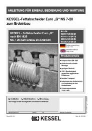
NOTICE D´INSTALLATION, DE MONTAGE ET D´ENTRETIENMicro station d'épuration KESSEL INNO-CLEAN +Micro station d'épuration totalement biologique pour le traitement deseaux usées ménagères, selon la EN 12566, partie IIIMicro station d´épurationINNO-CLEAN + pour une<strong>Installation</strong> à enterrer,dans les Grandeur nominalesEQ 4 à EQ 50L´ínstructionde service peut êtr<strong>et</strong>éléchargée vers l´avalwww.kessel.de enformat DIN A<strong>4.</strong>Avantages du produitDépenses d'énergie réduitesFaibles frais de maintenance <strong>et</strong>d'entr<strong>et</strong>ienDurée d'usage élevée grâce á la matièrePEEtanchéité absolue, cuve monolithique,fabrication par roto moulageLongévité, même avec des eaux uséesagressivesFaible poids, coût réduit d´installationpas de grande machine nécessaireHaute sécurité à la rupture.Classes de n<strong>et</strong>toyage C <strong>et</strong> D autoriséesZ-55.3-185L'installation Mise en service Initiation au systèmedu système a été exécutée par l'installateur spécialisé :Nom/Signature Date Lieu Cach<strong>et</strong> de l'installateur spécialiséSous toutes réserves de modifications techniquesMise à jour 04/2011N° d'ident. 010-430-FR
1. Consignes de sécuritéAttention ! Risque d'asphyxie en cas d´intervention dans la cuve.Le personnel affecté au <strong>montage</strong>, à la manipulation, à la maintenance <strong>et</strong> aux réparations doit présenterla qualification correspondant à ces travaux.L'exploitant doit dicter les règles exactes concernant les domaines de responsabilité, les compétences<strong>et</strong> la surveillance du personnel.La sécurité du fonctionnement du système fourni n'est assurée que si son utilisation est bien conformeà sa destination. Les valeurs limites des caractéristiques techniques ne doivent en aucun cas être dépassées.Ce système contient des parties sous tension électrique <strong>et</strong> commande des pièces mécaniques. Des dommagesmatériels considérables, des lésions corporelles <strong>et</strong> des accidents mortels peuvent résulter de lanon-observation des instructions de service.Il faut observer les prescriptions de prévention des accidents <strong>et</strong> les normes <strong>et</strong> directives DIN ou VDE entranten ligne de compte lors du <strong>montage</strong>, de l'utilisation, de la maintenance <strong>et</strong> de réparations du système.Il s'agit entre autres des :• « Prescriptions de prévention des accidents - Travaux de construction » BGV C22 auparavant VBG 37• « Fouilles <strong>et</strong> tranchées, talus, largeur d'espace de travail, étayage » DIN 4124• « Pose <strong>et</strong> contrôle de conduites <strong>et</strong> de canalisations d'eaux usées » DIN EN 1610• « Directives relatives aux travaux dans des réservoirs <strong>et</strong> des espaces étroits »BGR 117 auparavant ZH1/77Avertissement !Le couvercle du système d'épuration doit être suffisamment sécurisé contre toute ouverture non autorisée(notamment par des enfants), y compris pendant les phases de d´installation.Le système est constitué de plusieurs composants. C'est pourquoi vous devez tenir compte des différentschapitres des instructions de service. Il faut toujours, pour chaque <strong>montage</strong>, maintenance, inspection <strong>et</strong>réparation sur un des composants, m<strong>et</strong>tre l'ensemble du système hors service en r<strong>et</strong>irant la prise de secteursur l'unité de commande <strong>et</strong> le sécuriser contre tout ré enclenchement. Assurez-vous que le flux d'arrivéed'eaux usées est interrompu pendant le <strong>montage</strong>.L'appareil de commande est sous tension <strong>et</strong> ne doit pas être ouvert.Seuls des professionnels qualifiés doivent exécuter des travaux sur les dispositifs électriques.L'appellation d'électricien qualifié est définie dans la norme VDE 0105.Il est interdit d'effectuer tous travaux sur le compresseur sortant du cadre des activités décrites au chapitrerelatif à l'inspection <strong>et</strong> à la maintenance.Attention !Il faut s'assurer que les câbles électriques ainsi que toutes les pièces électriques du système sont enparfait état. Le système ne doit en aucun cas être mis en service s'il est endommagé.Toute transformation ou modification du système ne doit être faite qu'en concertation avec le constructeur.Les pièces de rechange d'origine <strong>et</strong> les accessoires autorisés par le constructeur servent à la sécurité.L'emploi d'autres pièces peut entraîner l'exclusion de toute responsabilité pour les conséquencesqui en résultent.49
Sommaire1. Consignes de sécurité .......... .............................................................................................. Page 492. Généralités 2.1 Champ d'application ............................................................... Page 522.2 Description du système............................................................ Page 522.3 Configuration de l´installation.................................................. Page 532.4 Dimension <strong>et</strong> volume............................................................... Page 542.5 Description du fonctionnement................................................ Page 593. Emballage, transport 3.1 Emballage................................................................................ Page 61<strong>et</strong> entreposage 3.2 Transport................................................................................. Page 613.3 Entreposage............................................................................ Page 61<strong>4.</strong> <strong>Installation</strong> <strong>et</strong> <strong>montage</strong> <strong>4.</strong>1 Lieu de l´installation .................................................................. Page 62<strong>4.</strong>2 La Fouille .................................................................................. Page 62<strong>4.</strong>3 Mise à niveau du fond de fouille. .............................................. Page 62<strong>4.</strong>4 La pose ..................................................................................... Page 63<strong>4.</strong>5 Remplissage de la cuve............................................................ Page 63<strong>4.</strong>6 Remblaiement........................................................................... Page 63<strong>4.</strong>7 Raccordement .......................................................................... Page 63<strong>4.</strong>8 Montage des tuyaux pneumatiques.......................................... Page 64<strong>4.</strong>9 Mise en place des rehausses ................................................... Page 65<strong>4.</strong>10 Remplissage final ................................................................... Page 66<strong>4.</strong>11 <strong>Installation</strong> du gestionnaire <strong>et</strong> du compresseur...................... Page 675. Mise en service 5.1 Mise en service de l´installation................................................ Page 705.2 Recommandation à l´utilisateur ................................................ Page 715.3 Explication du fonctionnement ................................................. Page 716. Entr<strong>et</strong>ien <strong>et</strong> vidange de boue 6.1 Phase de fonctionnement.................................................... Page 716.2 Vérification par l´utilisateur ...................................................... Page 726.3 Consignes d´enlèvement des boues ................................. Page 736.4 Elimination............................................................................... Page 747. Maintenance 7.1 Décantation <strong>et</strong> traitement ........................................................ Page 757.2 Compresseur........................................................................... Page 767.3 Diagnostics <strong>et</strong> erreurs ............................................................. Page 768. Programmation de la micro station 8.1 Menu du système .................................................................... Page 798.2 Menu - Information .................................................................. Page 798.3 Menu - entr<strong>et</strong>ien....................................................................... Page 798.4 Menu - programmation............................................................ Page 809. Pannes - solutions ................................................................................................ Page 8110. Garantie ........................................................................................................ Page 8411. Certificat de l´installation/ mise en service .............................................................................................. Page 8512. . Certificat de conformité ........................................................................................................ Page 8613. Rapport journalier ........................................................................................................ Page 871<strong>4.</strong> Piéces détanchée ........................................................................................................ Page 8815. Instructions d´entr<strong>et</strong>ien ........................................................................................................ Page 8916. Information technique ........................................................................................................ Page 90Rapport sur l´installation ........................................................................................................ Page 9150
Cher client,Nous nous réjouissons que vous vous soyez décidé en faveur d'un produit de KESSEL.L'ensemble du système a été soumis à un contrôle de qualité sévère avant de quitter l'usine. Veuillez contrôler immédiatementsi le système a bien été livré chez vous compl<strong>et</strong> <strong>et</strong> sans dommages. Veuillez tenir compte, en cas de dommagespendant le transport, des instructions du chapitre « Garantie » de ces instructions.Ces instructions de <strong>montage</strong>, de service <strong>et</strong> de maintenance contiennent des remarques importantes devant être observéesau moment du <strong>montage</strong>, de la maintenance <strong>et</strong> de réparations. L'exploitant <strong>et</strong> le personnel spécialisé responsabledoivent les lire avec attention <strong>et</strong> les suivre avant tous travaux sur le système.KESSEL51
2. Généralités2.1 Champ d'applicationINNO-CLEAN + , le système d'épuration de KESSEL est unsystème de n<strong>et</strong>toyage pour les eaux usées ménagères conformeà la norme DIN 4261 Partie II / EN 12566, Partie I <strong>et</strong>Partie III. Ce système n'est pas prévu pour les eaux uséesde précipitation, les eaux usées provenant de l'élevage d'animaux,ni les eaux usées de piscines. Ce système d'épurationn<strong>et</strong>toie, par un procédé biologique, les eaux usées ménagères<strong>et</strong> s'adapte automatiquement aux quantités qui surviennent.Les eaux usées sont collectées dans un réservoiren plastique <strong>et</strong> n<strong>et</strong>toyées. Ce réservoir n'est pas prévupour l'étayage en terre. L'aération <strong>et</strong> la circulation sont entièrementrégulées automatiquement par une unité de commande.Celle-ci est prévue pour un <strong>montage</strong> libre dans deslocaux secs protégés contre le gel <strong>et</strong> les inondations. La conduited'alimentation doit être raccordée sans refoulement àl'INNO-CLEAN + . Il faut, outre la conduite d'alimentation dusystème d'épuration, prévoir une conduite d'évacuation deseaux usées conforme à la norme ATV-DVWK-A138. Enoutre, la commune, le district ou l'administration responsablesdes eaux du plus bas niveau de hiérarchie sont compétentspour délivrer les permis de construction <strong>et</strong> d'exploitation.2.2 Description de l'installationKESSEL INNO-CLEAN + est composé de deux unités principaux.Le Boîtier de commande <strong>et</strong> compresseur qui doiventêtre installés à l'abri du gel <strong>et</strong> protégé contre l´humidité lacuve en matière PE dans laquelle se déroule le processusde purification <strong>et</strong> qui est situé en dehors du bâtiment, en poseenterrer. Boîtier de commande (Gestionnaire <strong>et</strong> compresseur) Entrée Compartiment de décantation primaire Compartiment à lit bactérien Cartouche d'aérateur Puisard (optionnel) Vannes pneumatiques Tourelle d'épuration avec bac de prélèvement, élémentair lift <strong>et</strong> écoulement intégré Gaine pour câbles Conduite de ventilation52
2. Généralités2.<strong>4.</strong> Masse <strong>et</strong> volume utileEinwohnergleichwertEquivalenthabitant (EW)(EW)maximalerVolume Schmutz-maxwasserzulaufen arrivée(l/Tag)ArtikelnummerNuméro d'article classeReinigungsklassede n<strong>et</strong>toyageC DQuantitéAnzahlconteneursBehälterEntrée Zu-/Ablauf <strong>et</strong>Sortie (DN) DNVolumesGesamtvolumentotaux(l)Länge(mm)Breite(B) (mm)Longueur (L) (mm) LargeurProfondeur Tiefe du niveausupérieure GOK bis Sohle du terrain Zulauffil d´eau (mm) (T)TTEÜ (mm) EÜ(mm)Grundwasser(GW) Nappephréatique(mm)(h2) Höhe HauteurZulauf entrée(mm)Höhe(h1) HauteurAuslaufsortie (mm) (mm)HöheHauteur Kabelleerrohrpour gaineá câbles(hleer)(mm)Gewicht Poids(ca. kg) kg)Gesamt Behälter 1 Behälter 2 Behälter 3 Behälter 4 Behälter 5 Behälter 6 L 1 L 2 L 3 b1=b2 min max4 600 97804 RC 97804 RD 1 150 4800 4800 2350 2000 604 1054 T-255 1775 1875 1775 2000 5306 900 97806 RC 97806 RD 1 150 4800 4800 2350 2000 604 1054 T-255 1775 1875 1775 2000 5308 1.200 97808 RC 97808 RD 1 150 7600 7600 3470 2000 604 1054 T-255 1775 1875 1775 2000 70010 1.500 97810 RC 97810 RD 1 150 7600 7600 3470 2000 604 1054 T-255 1775 1875 1775 2000 70012 1.800 97812 RC 97812 RD 2 150 9600 4800 4800 2350 2350 2000 604 1054 T-255 1775 1875 1775 2000 97014 2.100 97814 RC 97814 RD 2 150 12400 7600 4800 3470 2350 2000 604 1054 T-255 1775 1875 1775 2000 113016 2.400 97816 RC 97816 RD 2 150 12400 7600 4800 3470 2350 2000 604 1054 T-255 1775 1875 1775 2000 113018 2.700 97818 RC 97818 RD 2 150 15200 7600 7600 3470 3470 2000 604 1054 T-255 1775 1875 1775 2000 130020 3.000 97820 RC 97820 RD 2 150 15200 7600 7600 3470 3470 2000 604 1054 T-255 1775 1875 1775 2000 130022 3.300 97822 RC 97822 RD 3 150 18300 5350 7600 5350 2350 3470 2350 2000 604 1054 T-255 1775 1875 1775 2000 143024 3.600 97824 RC 97824 RD 3 150 21000 8100 4800 8100 3470 2350 3470 2000 604 1054 T-255 1775 1875 1775 2000 154026 3.900 97826 RC 97826 RD 3 150 21000 8100 4800 8100 3470 2350 3470 2000 604 1054 T-255 1775 1875 1775 2000 154028 <strong>4.</strong>200 97828 RC 97828 RD 3 150 23800 8100 7600 8100 3470 3470 3470 2000 604 1054 T-255 1775 1875 1775 2000 170030 <strong>4.</strong>500 97830 RC 97830 RD 3 150 23800 8100 7600 8100 3470 3470 3470 2000 604 1054 T-255 1775 1875 1775 2000 170032 <strong>4.</strong>800 97832 RC 97832 RD 6 150 31000 5350 5350 4800 5350 4800 5350 2350 2350 2350 2000 604 1054 T-255 1775 1875 1775 2000 262034 5.100 97834 RC 97834 RD 6 150 31000 5350 5350 4800 5350 4800 5350 2350 2350 2350 2000 604 1054 T-255 1775 1875 1775 2000 262036 5.400 97836 RC 97836 RD 6 150 31000 5350 5350 4800 5350 4800 5350 2350 2350 2350 2000 604 1054 T-255 1775 1875 1775 2000 262038 5.700 97838 RC 97838 RD 6 150 36600 5350 5350 7600 5350 7600 5350 2350 3470 2350 2000 604 1054 T-255 1775 1875 1775 2000 295040 6.000 97840 RC 97840 RD 6 150 36600 5350 5350 7600 5350 7600 5350 2350 3470 2350 2000 604 1054 T-255 1775 1875 1775 2000 295042 6.300 97842 RC 97842 RD 6 150 36600 5350 5350 7600 5350 7600 5350 2350 3470 2350 2000 604 1054 T-255 1775 1875 1775 2000 295044 6.600 97844 RC 97844 RD 6 150 36600 5350 5350 7600 5350 7600 5350 2350 3470 2350 2000 604 1054 T-255 1775 1875 1775 2000 295046 6.900 97846 RC 97846 RD 6 150 42000 8100 8100 4800 8100 4800 8100 3470 2350 3470 2000 604 1054 T-255 1775 1875 1775 2000 315048 7.200 97848 RC 97848 RD 6 150 42000 8100 8100 4800 8100 4800 8100 3470 2350 3470 2000 604 1054 T-255 1775 1875 1775 2000 315050 7.500 97850 RC 97850 RD 6 150 42000 8100 8100 4800 8100 4800 8100 3470 2350 3470 2000 604 1054 T-255 1775 1875 1775 2000 3150Veuillez considérer : Des influences liées aux conditions météorologiques ou le refroidissement, pendant la phase de pose(remplissage avec l'eau froide), peut-être à l´origine de déviations des indications de mesure.Veuillez vérifier en particulier, avant la pose, les dimensions de hauteur par rapport aux indications.54
2. GénéralitésConfiguration des installations EQ 4, EQ 6, EQ 8 EQ <strong>et</strong> 10Bac de prélèvementCapteur de chargementElément de renvoie des eaux clairesTrop pleinElément de renvoie d'excédent de boueCommutateur de flotteurCartouche de ventilation aérateurEntréeBd kg/d BSB5 Fr<strong>et</strong>/jourQd m 3 /d Arrivé eau usée / jourQ10 m 3 /h max. Arrivé eau usée /heureVdz m 3 max. Eau usée /cycleEntréeDN 150Dépôt de matièrelourde <strong>et</strong>décantationde bouesAération SBRSortieDN 150VoluminaVr, moyen m 3 Volume de réacteur moyen,Vr, max m 3 Volume de réacteur maximalVr, min m 3 Volume de réacteur minimalVs m 3 Volume minimal de bouesVp m 3 Volume de stockage de boueVs, ges m 3 Volume utile du réservoir de bouesHauteurHr max m Niveau d'eau maximal pour traitementHr min m Niveau d'eau minimal pour traitementHs m Niveau d'eau minimal réservoir debouesHp m Hauteur du tampon dans le réservoirHges m Niveau d'eau maximal réservoir debouesCuve en PE Variante mono cuveEntrée MasseVolume Hauteur Surface55
2. GénéralitésConfiguration des installations EQ 12, EQ 14, EQ 16 <strong>et</strong> EQ 20Bac de prélèvementCapteur de chargementElément de renvoie des eaux clairesTrop pleinElément de renvoie d'excédent de boueConteneur 1Commutateur de flotteurCartouche de ventilation aérateurEntréeBd kg/d BSB5 Fr<strong>et</strong>/jourQd m 3 /d Arrivé eau usée / jourQ10 m 3 /h max. Arrivé eau usée /heureVdz m 3 max. eau usée /cycleEntréeDN 150SortieDN 150VoluminaVr, moyen m 3 Volume de réacteur moyen,Vr, max m 3 Volume de réacteur maximalVr, min m 3 Volume de réacteur minimalVs m 3 Volume minimal de bouesVp m 3 Volume de stockage de boueVs, ges m 3 Volume utile du réservoir de bouesLignes de connexion DN 150Conteneur 2Elément aérateurpour tuyau 1+ 2HauteurHr max m Niveau d'eau maximal pour traitementHr min m Niveau d'eau minimal pour traitementHs m Niveau d'eau minimal réservoir debouesHp m Hauteur du tampon dans le réservoirHges m Niveau d'eau maximal réservoir debouesDépôt de matièrelourde <strong>et</strong>décantationde bouesAérationSBRCuve en PE Variante deux cuveEntrée MasseVolume Hauteur Surface56
2. GénéralitésConfiguration des installations EQ 22 - EQ 30Elément de renvoie des eaux clairesBac de prélèvementCapteur de chargementTrop pleinElément de renvoie d'excédent de boueDépôt de matière lourde<strong>et</strong> décantation de bouesCommutateur de flotteur Cartouche de ventilation aérateur 2Cartouche de ventilation aérateur1AérationSBREntréeDN 150Dépôt de matière lourde<strong>et</strong> décantation de bouesAérationSBRSortieDN 150Conteneur 1 Conteneur 2 Conteneur 3Vue de faceEntréeBd kg/d BSB5 Fr<strong>et</strong>/jourQd m 3 /d Arrivé Eau usée / jourQ10 m 3 /h max. Arrivé Eau usée /heureVdz m 3 max. Eau usée /cycleVoluminaVr, moyen m 3 Volume de réacteur moyen,Vr, max m 3 Volume de réacteur maximalVr, min m 3 Volume de réacteur minimalVs m 3 Volume minimal de bouesVp m 3 Volume de stockage de boueVs, ges m 3 Volume utile du réservoir de bouesCuve en PE Variante trois cuveEntrée MasseVolume Hauteur Surface57
2. GénéralitésConfiguration des installations EQ 32 - EQ 5058
2. Généralités2.5. Description du fonctionnementLe processus d'épuration est automatiquementrégulé par le gestionnaire. Un cycled'épuration dure environ 8 heures <strong>et</strong> se terminepar lʼévacuation de l'eau purifiée. Leprocessus de clarification se base sur desmicro-organismes qui se charge de la purificationdes eaux.1. Les eaux usées arrivent dans le premiercompartiment ou est appliqué une phasede décantationLes eaux usées arrivent dans le premiercompartiment ou est appliqué une phase dedécantationL´ors de la phase de décantation les matièreslourdes se déposent au fond <strong>et</strong> formentune couche de boue. Les boues d'eauxrésiduaires restent dans le compartimentde décantation primaire <strong>et</strong> devront êtreéliminées lorsque la capacité d'absorptionmaximale aura été atteinte.2. . Remplissage du compartimentd´activation (chargement)Le compartiment à lit bactérien est rempliavec les eaux usées provenant de du compartimentde décantation primaire. Un volumed'eaux usées défini, en provenance ducompartiment de décantation primaire estenvoyer, au moyen du système air lift, dansle compartiment de traitement.3. Phase de traitement des eaux usées(phase normale, économique ou vacance)Dans le compartiment de traitement des eauxusées. Des pulsations d´air en phase séquentiellesont envoyées (cartouche de ventilationà membrane). Par La ventilation séquentielle,l'oxygène arrive dans les eauxusées; les micro-organismes s´enrichid´oxygène afin de détruire les substances nutritives.Il se forme ainsi de la boue activée. Lemétabolisme des micro-organismes n<strong>et</strong>toieles eaux usées. La phase de traitement durehabituellement environ six heures. En outre,l'installation est réglée en fonction de son chargement.Le traitement d'eaux usées passealors dans le cadre de la "phase normale", dela "phase économique" ou de la "phasecongé". (voir point 6.1)59
2. Généralités<strong>4.</strong> Phase de décantationUne phase de décantation de 2 heures suitla phase de traitement. Toutes Les matièressolides contenues dans les eaux uséesainsi que la boue activée se déposent aufond du bassin, ce qui est lʼorigine de formationd´une couche d'eau claire dans lazone supérieure, tandis quʼune couche deboue des micro-organismes se dépose aufond.5. Evacuation de l'eau claire(renvoie de lʼeau claire)Maintenant, au-dessus de c<strong>et</strong>te couche deboue, il ne reste que de l'eau purifiée qui parl´intermédiaire de l´air lift est renvoyer versl´extérieur, vers un puisard, en milieu naturelou en filtration.6. Renvoie du micro organisme vers lecompartiment de décantationLa boue activée excédentaire est renvoyéedans le compartiment de décantation primaire.60
3. Emballage, transport <strong>et</strong> stockageIl faut tenir compte du chapitre traitant des consignesde sécurité !3.1 EmballageIl n'est pas nécessaire d'emballer les réservoirs en vue deleur transport ou de leur entreposage si on tient compte despoints suivants.Note : Il faut éviter tout pénétration de corps étrangers (sal<strong>et</strong>é,poussières <strong>et</strong>c.) dans le système d'épuration. Il faut, lecas échéant, poser des couvercles sur toutes les ouvertures.3.2 Transportl Le transport ne doit être effectué que par des sociétés disposantde l'expérience professionnelle, des appareillages,dispositifs <strong>et</strong> moyens de transport adaptés, ainsi que de personnelsuffisamment formé.l Les réservoirs doivent être transportés de manière à ne pasêtre sollicités au-delà de ce qui est admis <strong>et</strong> que tout changementde position pendant le transport soit exclu. En casde haubannage, il faut procéder à ce dernier de façon à ceque tout endommagement des réservoirs soit exclu (p. ex.emploi de courroies en tissu, de cordes en chanvre). Il estinterdit d'employer des câbles métalliques ou des chaînes.l Les réservoirs doivent être sécurisés contre tout changementde position non autorisé pendant leur convoyage. Lesréservoirs ne doivent pas être endommagés par le type defixation. Il est interdit de faire rouler ou glisser le conteneursur un fond à vives arêtes. Le conteneur, pour des raisonsdues au chargement <strong>et</strong> au déchargement, peut être pousséou tiré sur la surface de chargement d'un camion.3.3 EntreposageS'il devait être nécessaire d'entreposer les réservoirs avantleur <strong>montage</strong>, ce dernier ne doit avoir lieu que pour une périodebrève <strong>et</strong> sur un sol plat libre d'obj<strong>et</strong>s contondants. En casd'entreposage à l'air libre, les réservoirs doivent êtreprotégés contre les endommagements, les eff<strong>et</strong>s de latempête <strong>et</strong> la salissure.l Il faut éviter toute espèce de choc au moment de soulever,de déplacer <strong>et</strong> de déposer les réservoirs. Si on emploie unchariot élévateur, il faut assurer les réservoirs pendant le déplacementavec ce dernier. Il est interdit de faire rouler ou d<strong>et</strong>raîner les réservoirs sur le sol.l Veuillez observer :Le réservoir ne doit être être soulevé qu'à l'aide de sanglesde r<strong>et</strong>enues autorisées pour soulever des charges (n'employeren aucun cas des courroies de fixation).61
<strong>4.</strong> <strong>Installation</strong> <strong>et</strong> <strong>montage</strong>Pendant l'entreposage d'une micro station d'épurationainsi que jusqu'à la conclusion des travaux d'installation,des mesures de protection appropriées doivent êtreprises sur le chantier de construction pour empêcherdes accidents <strong>et</strong> endommager la micro station d'épuration.Il faut respecter le chapitre des consignes de sécurité.Conditions de <strong>montage</strong>Le <strong>montage</strong> ne peut être exécuté que par des entreprises quidisposent des expériences professionnelles, des appareilsappropriés <strong>et</strong> des installations ainsi que dʼun personnel suffisammentformé. Une étude de la nature du sol en vue del'aptitude technique de la construction doit avoir été entreprise(classification des sols pour des buts techniques deconstruction DIN 18196). ). Le niveau de la nappe phréatiquepouvant être présent doit également avoir été déterminéavant le début des travaux de construction. Un drainage suffisantdes eaux dʼinfiltration est souvent nécessaire en casde sols imperméables. Les types de charge susceptibles dese produire de même que les charges de circulation maximales<strong>et</strong> la profondeur d'installation doivent être clarifiées.Aperçu des étapes du <strong>montage</strong> (voir aussi <strong>4.</strong>1 à <strong>4.</strong>12)1. Choisir l'endroit d'installation.2. Préparer la fouille.3. Préparer un radier au niveau.<strong>4.</strong> Placer la cuve dans la fouille.5. Remplir à moitie les compartiments de la cuve avec del´eau.6. Remplir par couches <strong>et</strong> comprimer la fouille avec du gravier(jusqu'à la sortie).7. Raccorder les entrées <strong>et</strong> les sorties, ainsi que la conduitede ventilation <strong>et</strong> la gaine pour le câblage.8. M<strong>et</strong>tre en place le tuyau flexible de ventilation <strong>et</strong> la lignede commande dans la gaine à câbles.9. Fixer l'anneau de serrage sur la rehausse <strong>et</strong> la positionner10. Finir le remplissage de la cuve11. Monter la console murale, le compresseur <strong>et</strong> raccorder laconduite d´air12. Mise en service de l'installation (voir chapitre 5).<strong>4.</strong>1 Emplacements de <strong>montage</strong>Immédiatement avant la mise en place de la cuve dans lafouille, le représentant de la société, en compagnie du responsablechargé du <strong>montage</strong> doit contrôler <strong>et</strong> certifier lespoints suivants :- L'intégrité de la paroi de la cuve;- L'état réglementaire de la fouille, en particulier par rapportaux mesurages <strong>et</strong> de la dalle de fondation;- Qualité de la granulation du matériau de remplissage.La distance entre le pupitre de commande <strong>et</strong> le de la cuvene doit pas être supérieure à 12,5 m (option : 30 m - ensemblede tuyaux = distance 27,5 m). Si cela ne suffit pas,le pupitre de commande <strong>et</strong> le compresseur peuvent être installésdans une armoire de commande optionnelle.En cas dʼinstallations avec plusieurs cuves, la distance maximaleest 3,0 m. Si c<strong>et</strong>te distance est dépassée, des tuyauxsupplémentaires sont nécessaires.➁➀➁Les plus grandes installations INNO-CLEAN ® se composent de deux ou de davantagede conteneurs. Ceux-ci peuvent être attribués individuellement dans desvariantes différentes. Il est ainsi possible de faciliter le <strong>montage</strong> même dans lescas les plus difficiles.<strong>4.</strong>2 FouilleRemarque: En cas d'installation à plusieurs cuves creuserune fouille de d´installation pour tous les cuves!Le sol à bâtir doit être horizontal <strong>et</strong> plat afin de pouvoir positionnerl'installation sur toute la surface. En outre, le sol àbâtir doit garantir une force portative suffisante. Comme soubassement,on utilisera obligatoirement du gravier rond compressé(granulation 8/16, épaisseur minimale 30 cm, Dpr=95%) avec au dessus 3 - 10 cm de sable compressé. La distanceentre le mur de fouille <strong>et</strong> le conteneur doit être aumoins 70 cm. Les pentes doivent correspondre à la DIN412<strong>4.</strong>• <strong>Installation</strong> sur un terrain en penteEn cas dʼinstallation d'une micro station d'épuration sur unterrain en pente, il faut impérativement faire attention à ceque la poussée des terres exercée latéralement soit étayéepar un mur d'appui conçu en conséquence.• Profondeur à lʼabri du gelLors de l'installation d'une micro station d'épuration il fautimpérativement que la profondeur prévue pour la recevoirsoit à lʼabri du gel. Pour garantir un fonctionnement sans problèmeégalement en hiver, il faut également que les entrées<strong>et</strong> sorties de lʼalimentation aient été conçues pour être à lʼabridu gel. En règle générale, la profondeur à lʼabri du gel,sauf autre indication donnée par les services publics donné,se situe à environ 80 cm.<strong>4.</strong>3 Couches de propr<strong>et</strong>éFond de fouille : gravier roulé(granulation 8/16) selon DIN 4226-1Radier pour la cuve : sableRemblaiement : gravier roulé(granulation 8/16) selon DIN 4226-1Zone extérieure➀62
<strong>4.</strong> <strong>Installation</strong> <strong>et</strong> <strong>montage</strong>≤ 20cm≤ 30cm≤ 30cm≤ 30cm≥ 50cm≥ 50cm≤ 30cm≤ 30cm≤ 30cm≤ 30cm≤ 30cmβ nachDIN 4124≤ 30cm3-10cm≥ 30cm≥ 70cm fondement : gravier rond (granulation maximale 8/16) selonDIN 4226-1 compressé avec Dpr=95 % lits de conteneur : sable compressé Cuve≥ 70cm enveloppement du conteneur : gravier rond (granulation maximale8/16) selon DIN 4226-1 compressé avec Dpr=95 % zone à lʼextérieur de lʼenveloppement du conteneur:matériau de qualité appropriée couches de couverture : humus, tapis routier, béton ou autres.Remblaiement de la cuve: matériau de qualité appropriéeCouche de couverture : humus ou autre (tenir compte de laclasse de charge)<strong>4.</strong>4 Mise en placeLa pose le la cuve dans la fouille doit être mis en place sanschocs, dans la fouille à l'aide d'un dispositif approprié <strong>et</strong> déposésur la dalle de fondation (voir aussi chapitre "Transport").Lors de la mise en place faire attention au sensd´écoulement voir flèche entrée-sortie<strong>4.</strong>5 5 Remplissage du conteneurRemplir avec de l'eau claire les deux compartiments de lacuve (environ 80 cm) pour avoir une meilleure stabilité.<strong>4.</strong>6 Remblayage de la fouilleEn règle générale, le remplissage de la cuve <strong>et</strong> le remblayagede la fouille doivent être réalisés parallèlement. Leremblayage de la fouille sʼexécute jusqu'au bord inférieur delʼentrée <strong>et</strong> de la sortie ainsi que des conduits de ventilation<strong>et</strong> de câblage. L'enveloppement du conteneur doit avoir unelargeur d'au moins 50 cm. Les différents dépôts du matérielde remplissage ne doivent pas avoir une hauteur supérieureà 30 cm. Ils doivent être compressés avec des compacteurs(Dpr min. =95 %). Après le remblayage, il est exclu de déplacerou bouger la cuve sans endommager celle ci.<strong>4.</strong>7 TuyauteriesUne proposition pour la pose de pipelines peuvent être trouvéessur les pages 224-227. Les alimentations dʼentrée <strong>et</strong> desortie ainsi que les conduites de connexion doivent êtreconçues pour être à lʼabri du gel (voir <strong>4.</strong>2) <strong>et</strong> raccordés dèsque la fouille est compacté <strong>et</strong> remplies jusqu'au bord inférieurdes conduites dʼentrée <strong>et</strong> de sortie. Le passage à lʼhorizontaledes lignes de descente est à réaliser avec deux piècesarquées à 45 ° <strong>et</strong> une pièce intermédiaire d'au moins 250 mmde long. A l´entrée de la cuve il faut prévoir une distanced´apaisement des fluides dont la longueur corresponde à aumoins dix fois le diamètre nominal de la conduite.• Gaine pour câblageLa liaison entre le boîtier de commande / compresseur <strong>et</strong>bloc de soupape / cuve INNO-CLEAN + sera assurée parune gaine pour câbles (tube KG en PVC <strong>et</strong> de dimension63
<strong>4.</strong> <strong>Installation</strong> <strong>et</strong> <strong>montage</strong>Dalle en bétonJoint réf : 860116Dispositifd´étanchéitéRéf : 97711CloisonTube DN 100 (Ø110)Joint au passagedes tubesParoi de la cuveINNO-CLEANRéalisation depassage decloisonPentes au minimum de2° par rapport au cuveBloc de soupapeInno-CleanDN 100). La gaine vide doit avoir sur toute sa longueur unepente permanente de ≥ 2 ° ° vers la cuve. Pour la réalisationdu mur du bâtiment, KESSEL recommande d'avoir recours àdes réalisations commerciales (voir figure).Pour l´étanchéitée de la gaine pour câbles située dans lebâtiment, KESSEL propose une pièce spéciale (Référencede commande 97711) afin dʼobtenir une protection contre lesodeurs.Les changements de direction doivent être réalisés avec descoudes avec un angle de 30 ° au maximum.Attention: toutes les conduites, quʼelles soient temporairesou définitives, doivent être étanchéifiées avec du scotch pouréviterl'entrée d´impur<strong>et</strong>és l´ors der la pose.Remarque:Dans la zone du trou d homme, les cuves peuvent être percépour les conduites de raccordement <strong>et</strong> de ventilation supplémentaires.Il faut alors utiliser les couronnes de scie clocheoriginales <strong>et</strong> les joints de passage pour tube de KESSEL(KESSEL - Scie cloche DN 50 - DN 150, référence 50100)Dispositif d´étanchéité KESSEL:DN 50 Réf : 850114DN 70 Réf : 850116DN 100 Réf : 850117DN 125 Réf : 850118DN 150 Réf : 850119)Les percements doivent être exécutés, si possible, sur dessurfaces planes. Pour une étanchéité optimale du percement,la distance entre le bord <strong>et</strong> le contour inégal, doit êtreau moins 15 mm afin que le joint soit positionné de façon régulièreautour du trou.• VentilationLa ventilation de l'installation se fait via une conduited´alimentations. Dans un diamètre DN 100 (Ø110) . Uneconduite de ventilation secondaire peut être raccordé autrou d´homme. Dans ce cas, il faut utiliser la scie cloche corres-pondante<strong>et</strong> le joint adéquat KESSEL (voir la figure enpage 5). KESSEL recommande l'application d'un filtre à charbonactif pour éviter les mauvaises odeurs.Plaqued'adaptationLangu<strong>et</strong>te pouraccrocher le câblede commandeLigne de commandeFlexibles pour les airs liftsFlexible dʼair pour compresseurRaccord rapideBloc de soupapeLevier deverrouillage<strong>4.</strong>8 Pose des lignes de connexion pour lʼunité de commande(tuyau flexible de ventilation <strong>et</strong> ligne de commande)Les conduites de commande sont à placer en gaine <strong>et</strong> à raccorderau gestionnaire <strong>et</strong> au bloc de vannes pneumatiques(voir la procédure)Manière de procéder :- Débloquer le levier de verrouillage sur le bloc de soupapedans la cuve- R<strong>et</strong>irer le bloc de soupape de la plaque d'adaptation- Tirer le tuyau flexible de ventilation gris <strong>et</strong> le câble de commandeen passant par la gaine pour câbles.- Connecter le tuyau flexible de ventilation au bloc de soupapeau moyen dʼun raccord rapide (voir <strong>4.</strong>11 point 5)- Placer le bloc de soupape sur la plaque d'adaptation- Attention: le câble de commande doit être clipsé dans lalangu<strong>et</strong>te prévue à c<strong>et</strong> eff<strong>et</strong> (voir figure) afin dʼavoir unverrouillage correct avec la plaque d'adaptation.- Vérifier que le bloc de soupape est correctement positionné<strong>et</strong> bloquer la pièce de verrouillage64
<strong>4.</strong> <strong>Installation</strong> <strong>et</strong> <strong>montage</strong>Raccordement pneumatique bloc électrovanneRaccordement pneumatique compresseur.Cartouched´oxygénationAir-lift pour remplissageAir-lift pour l´extraction des eaux clairesAir-lift pour renvoi des boues<strong>4.</strong>9 Montage de la rehausseJoint de lèvre DN 600Rehausse télescopiqueAnneau de serrageTrou d´hommede la cuveProfondeurd'insertionminimale100 mmPlacer d'abord le joint (voir dessin <strong>4.</strong>9) dans la cannelureprévue dans le dôme.Avec un lubrifiant, graisser la partie bisoute de la rehausseKESSEL <strong>et</strong> le joint <strong>et</strong> emboiter dans le trous d´homme jusquʼàla position souhaité, puis fixer au moyen dʼun collier deserrage. Un ajustage de précision à la hauteur définitive peutêtre effectué á l´aide des vis de réglage. Les inclinaisons ausol peuvent être égalisées au moyen de la rehausse qui peutêtre inclinée <strong>et</strong> réglée de manière continue en hauteur jusquʼà5°. Les autocollants "Innofanten" fournis à la livraisondoivent être fixés sur la surface n<strong>et</strong>toyée <strong>et</strong> sèche de la rehausse(voir figurine).Important: Lʼauto-collant "Innofant" vert doit être appliquédu côté Entrée <strong>et</strong> rouge du côté sortie! Pour terminer, effectueren remblayage finale autour de la rehausse <strong>et</strong> colmater.65
<strong>4.</strong> <strong>Installation</strong> <strong>et</strong> <strong>montage</strong>Les lang<strong>et</strong>te du joint doivent être orientévers le fond de cuve.Entrée➔➔Sortie<strong>4.</strong>10 Remplissage finale de la cuveAvant de procéder au remplissage, vérifier une dernièrefois l'alimentation entrée <strong>et</strong> de sortie, ainsi que la conduitede ventilation <strong>et</strong> la gaine pour câbles. Egaliser la rehaussepar rapport au terrain66
<strong>4.</strong> <strong>Installation</strong> <strong>et</strong> <strong>montage</strong> Prise secteur Compresseur Consoles murale Boîtier de commande Raccordement compresseur Raccord pour contact libre de potentielle Raccordement bloc de vannes pneumatiques(y compris commutateur de flotteur) Raccord ém<strong>et</strong>teur de signaux extérieurs Raccord air pour vannes pneumatique Raccord détecteur pneumatique Raccord coudé pour branchement tuyau àair comprimé Raccord rapide<strong>4.</strong> 11 Montage du gestionnaire <strong>et</strong> du compresseurVeuillez faire attention à utiliser une gaine de minimum (DN 100)pour les lignes de raccordement allant du conteneur au pupitree de commande.Instructions généralesATTENTION : KESSEL recommande de faire exécuter lesraccordements électriques par une entreprise spécialiséeen électricité. Ne m<strong>et</strong>tez l'installation en servicequ’une fois que le <strong>montage</strong> est entièrement terminé.Pendant les travaux de raccordement, l'installation nedoit pas être sous tension.Le gestionnaire <strong>et</strong> le compresseur doivent être installé dansun local sec, <strong>et</strong> á l´abri du gel <strong>et</strong> des inondations. Il faut tenircompte dʼéventuel refoulement !Il faut assurer une bonne ventilation dans le local où le compresseurest installé. en particulier pour les appareils placésà l'intérieur d'un abri extérieure, afin deprotéger le compresseurcontre un surchauffe ment.Une température ambiante fraîche garantit une durée de vieélevée des membranes <strong>et</strong> des soupapes.Le compresseur ne doit pas se trouver dans un environnementpoussiéreux. Une surchauffe par des filtres bouchés réduitla durée de la vie des membranes <strong>et</strong> des filtres. Le compresseurdoit être protégé de la lumière directe du soleil, dela pluie, de la neige <strong>et</strong> du gel. L'air ambiant aspiré ne doit pascontenir des vapeurs ou de gaz inflammables ou agressifs.La tuyauterie flexible doit être aussi courte <strong>et</strong> rectiligne quepossible entre la commande <strong>et</strong> la cuve. Les changements dedirection doivent réalisés en effectuant de larges courbes.Le compresseur doit être positionné au-dessus du gestionnaireau moyen dʼun support approprié ou dʼune consolepour éviter dʼéventuels dommages. Si le <strong>montage</strong> est effectuésur un support instable, des bruits gênants peuvent êtregénérés par les vibrations.Le compresseur doit être monté horizontalement pourempêcher une charge unilatérale des membranes, ce qui réduiraitainsi la durée de vie des composants. Le compresseurdoit être placé sur 4 plots en caoutchouc<strong>et</strong> ne pas bouger.67
<strong>4.</strong> <strong>Installation</strong> <strong>et</strong> <strong>montage</strong>Montage <strong>et</strong> raccordement La console murale doit être fixée à lʼhorizontale sur lemur, au moyen des deux vis <strong>et</strong> chevilles fournies à lalivraison. Ouvrir le boîtier de commande en desserrant les quatrevis à tête cruciforme situées sur la face avant <strong>et</strong>fixer sa paroi arrière sur la console murale (en dessousde la surface de pose du compresseur) à lʼaidedes quatre vis à tête cruciforme fournies à la livraison.La ferm<strong>et</strong>ure du couvercle doit être effectuée avecune serrage de max 1Nm. Attention: vérifier auparavantque l'appareil est hors tension (voir les consignesde sécurité en page 2) Positionner le compresseur sur la surface de pose dela console murale, en utilisant les creux prévus à c<strong>et</strong>eff<strong>et</strong>. Veuillez bien faire attention que le voyant decontrôle soit placé vers lʼavant de l'appareil <strong>et</strong> que leraccordement électrique se trouve sur la droite de l'-appareil. La fiche de secteur du compresseur doitêtre connectée à l'embrayage Schuko de l'appareil decommande. Avant que le raccord angulaire pour le raccordementde la conduite pneumatique au compresseur à l'appareilne soit connecté, il faut introduire l'enveloppemétallique fournie à la livraison dans la longue branchedu raccord angulaire. Le <strong>montage</strong> du raccord angulairesʼexécute sur la tubulure du compresseur <strong>et</strong>sa fixation se fait sur lʼappareil au moyen du serrejointà ressort.Adaptation aux dimensions du compresseur EL 150/200/250 : r<strong>et</strong>irez le raccord du compresseur <strong>et</strong> vissezsur le fil<strong>et</strong>age du compresseur le raccord angulaire fourni à la livraison (étanchéifier le fil<strong>et</strong>age avec unebande téflon ou similaire). On ne peut pas utiliser de gaine métallique avec ces dimensions de compresseur. Ouvrir le raccord rapide en tournant le bouchon de ferm<strong>et</strong>ure de 60 ° vers la gauche <strong>et</strong> introduire la longueextrémité du raccord angulaire jusqu'à la butée. Fermer le couvercle de ferm<strong>et</strong>ure en tournant vers la droite. Le tuyau flexible transparent du capteur pneumatique doit être connecté au boîtier de commande avec latroisième douille de gauche. Pour ce faire, desserrer l'écrou à chapeau noir <strong>et</strong> r<strong>et</strong>irer l'anneau de serrage intégrépuis enfiler l'écrou à chapeau <strong>et</strong> l'anneau de serrage sur le tuyau flexible transparent <strong>et</strong> terminer enfixant le tuyau flexible. Enfin, visser fermement l'écrou à chapeau noir. Pour le raccordement de la conduite pneumatique du conteneur, il faut raccourcir le tuyau flexible de ventilationgris pour lʼadapter à la longueur appropriée dans la gaine pour câbles <strong>et</strong> le fixer au compresseur avecle raccord rapide sans le plier. Attention: le tuyau flexible de ventilation doit être souple <strong>et</strong> non pas tendu. Le câble de jonction du bloc de soupape doit enfiché dans la douille correspondante du boîtier de commande<strong>et</strong> fixé par vissage.68
<strong>4.</strong> <strong>Installation</strong> <strong>et</strong> <strong>montage</strong>Raccords optionnels sur l'appareil de commande :Attention: tous les raccords optionnels doivent être exécutés par des électriciens de métier.69
5. Mise en service écran / champ d'annonces touches de mouvement / touches de directionpour la commande via le menu de programme touche de confirmation / touche Ok touche r<strong>et</strong>our / touche ESC lampe témoin pour ordre de marche lampe témoin pour message de panne câbles de connexion secteur raccordement secteur pour compresseur raccords capteur pneumatique possibilités de connexion pour l'ém<strong>et</strong>teur designaux extérieur raccords bloc de soupape Raccord prise pour contact libre de potentielInstruction / TransfertIl faut respecter le chapitre des consignes de sécurité !(page 2)La mise en service eservice doit être exécutée par une entreprisespécialisée ou un mandataire KESSEL (contre majoration).Les personnes suivantes doivent être présentes lors dutransfert :- le représentant du maître de l'ouvrage- lʼentreprise spécialiséeNous recommandons en outre la participation du personnel /exploitant, de l'entreprise spécialisée dans l'élimination desdéch<strong>et</strong>sAperçu des consignes :5.1. Mise en ordre de marche de lʼinstallation5.2. Contrôle de l'installation5.3. Instruction au moyen des consignes de <strong>montage</strong> <strong>et</strong> dumode d'emploi5. <strong>4.</strong> Elaboration du procès-verbal de transfert. (voir chap. 13)Après la fin de l'instruction, l'installation doit être mise en étatprêt à fonctionner.5.1 Mise en ordre de marche de lʼinstallationAvant la mise en service, lʼinstallation doit être complètementn<strong>et</strong>toyée (y compris entrées <strong>et</strong> sorties); les matières solides doiventêtre r<strong>et</strong>irées.Les deux compartiments de la cuve doivent être remplis avecde l'eau claire jusqu'à une hauteur de 1,20 m. Les fiches desecteur du boîtier de commande sont insérées dans les prisesde courant. L'installation s'initialise dʼelle-même.0.systéme Systemstart departsystéme Systemdiagnose diagnose1.5 Systéme Systeminfo informationHeure: Uhrzeit: 20:45Flotteur: Schwimmer: S1S2Ereignisse:EvenémentsN<strong>et</strong>zausfall CoupureNormale Normalphase phase0.1 Sprache IdiomedeutschfranzösischenglischAllemandFrancaisAnglais0.2 Datum/UhrzeitDate/HeureDatumDate01.01.2009 Uhrzeit12:00 01.01.02009 Heure12:000.3 Klassen ClassificationCD0.4 Nenngrößen Grandeur nominaleEW4EW6EW8EW10…EW2470
5. Mise en serviceInstruction : la conduite de réseau doit être équipée dʼun automatede protection FI.Lors d'une première initialisation de l'installation, le boîtier decommande demande quatre mises au point de base. Les questionssuivantes apparaissent alors sur l'écran du boîtier decommande :1. Langue utilisée par lʼopérateur2. Date <strong>et</strong> heure3. Classe de n<strong>et</strong>toyage souhaitée C ou D<strong>4.</strong> Grandeur nominale nécessaire de l'installation.Le réglage souhaité peut être affiché sur une colonne de marquageen actionnant les touches de direction / les touches demouvement <strong>et</strong> la mise en action est confirmée par la touche devalidation du réglage choisi dans le système. Dès que les 4préréglages ont été exécutés, le boîtier de commande chargela mémoire du programme <strong>et</strong> passe de lui-même dans le moded'exploitation. L'installation est maintenant prête à fonctionner.Instructions relatives au r<strong>et</strong>our des boues :Le r<strong>et</strong>our des boues activées est nécessaire pour éviter laformation d'une trop grande quantité de boue activée. Un<strong>et</strong>rop grande quantité de boue activée pourrait entraîner desdysfonctionnements au niveau du départ de la station d'épuration<strong>et</strong> perturber éventuellement les stations d'éliminationdes eaux par infiltration disponibles. La quantité de boue der<strong>et</strong>our se dépose dans la chambre de pré-épuration <strong>et</strong> estévacuée avec l'élimination suivante des boues primaires.La commande du r<strong>et</strong>our des boues peut être réglée pendantles temps T20 <strong>et</strong> T21. Après la mise en service de l'installation,les deux r<strong>et</strong>ours des boues devraient être bloqués pendantles 3 à 5 premiers mois pour garantir une reformationplus rapide de la biologie. En outre, il peut être rationnel,après chaque élimination des boues primaires, de réduire leréglage T20 (voir point 6.4 Elimination des déch<strong>et</strong>s) afind'éviter une arrivée excessive en boues activées. Pour debons résultats de n<strong>et</strong>toyage, vous devez vous assurer que,conformément aux conditions d'exploitation, la quantité deboue activée se trouvant dans le bassin d'aération, se situeentre 300 ml/l <strong>et</strong> 600 ml/l. Si c<strong>et</strong>te valeur n'est pas atteinte, ilfaut réduire ou augmenter les valeurs préréglées du r<strong>et</strong>ourdes boues. Vous trouverez les valeurs préréglées de l'usinedans le tableau en page 77.5.2 Obligations de l'exploitantContrôle- Dégâts dus au transport ou au <strong>montage</strong>- Manques constructifs- Vérification de lʼemplacement <strong>et</strong> du fonctionnement de tousles composants électriques <strong>et</strong> mécaniques- Fonctionnement du flotteur- Raccordements de la tuyauterie- Contrôle des branchements des conduites- Siphon (voir point 8)- Aérateur5.3. Instruction du client au moyen desconsignes de <strong>montage</strong>- Voir avec le client les consignes de <strong>montage</strong> <strong>et</strong> lemode d'emploi- Exploitation de l'installation (explications <strong>et</strong> description)- Préciser au client les obligations de l'exploitant (éliminationdes déch<strong>et</strong>s, maintenance, exploitation d'une p<strong>et</strong>ite stationd'épuration biologique, journal d'entreprise)6. Entr<strong>et</strong>ien <strong>et</strong> vidange de boue6.1 ExploitationAprès la mise en service de l'installation, une couche de boueactive avec des micro-organismes se forme dans le compartimentd´activation durant les 3-6 mois. L´implantation demicro-organismes dans c<strong>et</strong>te installation est inutile. Cependant,nous considérons judicieux dʼavoir une amenée de laboue activée d´une station d'épuration voisine. Important:L´implantation de boue activée uniquement dans le compartimentde traitement!Les périodes de maintenance doivent être impérativementrespectées pour que lʼexploitation se déroule sans problème.Il faut sʼassurer que vidage des compartiments de décantationprimaire est exécuté dans les délaisL'exploitation d'une p<strong>et</strong>ite station d'épuration se déroule automatiquement.Il existe trois phases, "normale", "économique"<strong>et</strong> "congé". Celles-ci se différencient en fonction de leurdurée de ventilation <strong>et</strong> du volume. La clarification proprementdite a lieu durant la phase normale (6 heures).En cas de chargement insuffisant de l'installation (p<strong>et</strong>it apportd'eau usée), celle-ci passe indépendamment dans la"phase économique" (2 heures). Durant c<strong>et</strong>te phase, l<strong>et</strong>emps de ventilation est réduit en raison de la plus p<strong>et</strong>itequantité d'eaux usées, afin dʼempêcher que les micro-organismesne soient « affamés ». En cas de durée plus longuedans la "phase économique" (8 heures) la phase "congé" démarreautomatiquement.La phase "congé" se distingue par un approvisionnementd'oxygène encore plus réduit. A la fin de la phase de congé,une quantité de boue définie est déplacée le compartimentdʼactivation dans la décantation primaire. Cela perm<strong>et</strong> dʼavoirlors de lʼalimentation suivante une certaine quantité de substancenutritive dans le lit bactérien. Cela contribue à la conservationbiologique en cas dʼarrêt plus long.Dès que lʼeau dans le compartiment de décantation primaireest en quantité suffisante pour que le flotteur soit activé lorsquelʼalimentation est connectée, l'installation passe automatiquementen phase normale.71
6. Entr<strong>et</strong>ien <strong>et</strong> vidange de boueC<strong>et</strong>te adaptation aux différentes quantités d'eaux usées estréglée automatiquement par la commande. La phase correspondanteest affichée sur le gestionnaire. Vous trouverezun aperçu général sur les phases correspondantes <strong>et</strong> lescycles dans le chapitre 2.5.En respectant les recommandations suivantes, vous éviterezdes frais de réparation inutiles <strong>et</strong> vous augmenterez ladurée de la vie de votre installation :• L'installation doit rester continuellement allumée, mêmependant la durée des vacances..• L'eau claire, parasite, telle que de l'eau de pluie, de lʼeaude nappe phréatique, de piscine <strong>et</strong> d'aquarium ne doit pasêtre introduite• Veuillez faire attention à ce que les produits d´entr<strong>et</strong>ien ménagersnʼaient pas de réactions acide ou alcalines. Nous recommandonsdʼutiliser des n<strong>et</strong>toyants <strong>et</strong> des lessives biodégradables.• Les couvercles de l'installation doivent être ouverts doiventimpérativement avoir un accès.• Prenez toute disposition utile pour que l'installation soitrégulièrement entr<strong>et</strong>enue par une société spécialisée.• Seule la décantation primaire doit être régulièrement (environtous les 12-24 mois) débarrassée de sa boue par une entreprisespécialisée dans l'élimination des déch<strong>et</strong>s ! Cependantaprès consultation des services publics d'eau compétents <strong>et</strong>la conclusion d'un contrat de maintenance, ce point peut êtreaussi, si nécessaire, adapté à la demande.Remarque: En cas de mise hors service, il faut sʼassurer quel'installation reste remplie.Points à respecter impérativement:L´utilisation de produits de n<strong>et</strong>toyage <strong>et</strong> des lessives – respectezimpérativement les dosages indiqués par les fabricants!Vous pouvez également utiliser différents déboucheurs d<strong>et</strong>uyauterie mai respectez strictement le dosage indiquépar le fabricant.Cependant ces produits de n<strong>et</strong>toyage détruisent un grandnombre de bactéries. Si possible, donnez la préférenceaux n<strong>et</strong>toyants biodégradables <strong>et</strong> nʼutilisez pas de déboucheursde tuyauterie (voir 6.3).Instructions relatives au r<strong>et</strong>our des boues :Le r<strong>et</strong>our des boues activées est nécessaire pour éviter laformation d'une trop grande quantité de boue activée. Un<strong>et</strong>rop grande quantité de boue activée pourrait entraîner desdysfonctionnements au niveau du départ de la station d'épuration<strong>et</strong> perturber éventuellement les stations d'éliminationdes eaux par infiltration disponibles. La quantité de boue der<strong>et</strong>our se dépose dans la chambre de pré-épuration <strong>et</strong> estévacuée avec l'élimination suivante des boues primaires.La commande du r<strong>et</strong>our des boues peut être réglée pendantles temps T20 <strong>et</strong> T21. Après la mise en service de l'installation,les deux r<strong>et</strong>ours des boues devraient être bloqués pendantles 3 à 5 premiers mois pour garantir une reformationplus rapide de la biologie. En outre, il peut être rationnel,après chaque élimination des boues primaires, de réduire leréglage T20 (voir point 6.4 Elimination des déch<strong>et</strong>s) afind'éviter une arrivée excessive en boues activées. Pour debons résultats de n<strong>et</strong>toyage, vous devez vous assurer que,conformément aux conditions d'exploitation, la quantité deboue activée se trouvant dans le bassin d'aération, se situeentre 300 ml/l <strong>et</strong> 600 ml/l. Si c<strong>et</strong>te valeur n'est pas atteinte, ilfaut réduire ou augmenter les valeurs préréglées du r<strong>et</strong>ourdes boues. Vous trouverez les valeurs préréglées de l'usinedans le tableau en page 29.6.2 Contrôles exécutés par l'exploitantEn tant quʼexploitant de la station d'épuration, vous devez,vis-à-vis des services publics dʼalimentation en eau prendr<strong>et</strong>oute mesure pour que votre installation fonctionne sansproblème. Les incidents d'exploitation des micros stationsd'épuration biologiques ont un impact négatif sur la qualitéde l'eau purifier. Cʼest pourquoi un incident doit être immédiatementdétectés <strong>et</strong> remédié par vous-même ou par uneentreprise de maintenance qualifiée. Pour documenter vospropres contrôles, vous devez tenir un journal d'entreprise.A la fin de ce manuel, vous trouverez un document qui contienttoutes les données nécessaires. Les services publicsdes eaux peuvent exiger que vous leur présentiez ce journald'entreprise. Vous devez exécuter régulièrement les contrôlessuivants:Contrôles mensuels• Concernant la commande: Inscription dans le journal d'entreprisedes temps de fonctionnement de l'écran.• Concernant la décantation primaire : contrôle de la boue flottanteà la surface de l'eau. Celle-ci doit être r<strong>et</strong>irée ou épuréeavec de l'eau claire. Aucune boue ne doit parvenir dans lescompartiments à lit bactérien sans avoir été contrôlée. Laboue doit être éliminée avant que la capacité d'absorptionnʼait atteint 70 %. La mesure de l'épaisseur de la couche deboue sʼeffectue de la même manière que le mesurage du niveaud'huile dʼune voiture. Utilisez une longue perche ou unmoyen semblable. Enfoncez perche dans la compartimentde décantation primaire jusqu'à toucher le fond de la cuveR<strong>et</strong>irez-la ensuite <strong>et</strong> mesurez la couche de boue. Une mesureexacte peut être exécutée par du per-72
6. Entr<strong>et</strong>ien <strong>et</strong> vidange de bouesonnel spécialisé.• Concernant la chambre à lit bactérien : contrôle visuel de laclarté de l'eau• Contrôle visuel du mélange <strong>et</strong> de la présence de bulles d'airContrôles semestrielsMaintenance par une entreprise spécialisée. Il faut tenircompte des indications des services publics compétents. Sila hauteur de boue est de 95 cm par rapport au fond du conteneur,cela signifie quʼon a atteint environ 70% de la capacitéd'absorption.6.3 Points ne faisant pas partie d’une micro station d'épuration biologiqueDans votre propre intérêt, vous devez faire attention aux instructions suivantes:Matière lourde ou fluide, qui Ce que vous faites Où vous êtes en de bonnes mainsne doivent dans aucun cas êtredéversé dans la micro station.Cendre ne se dégrade pas PoubellePréservatifs Obturations PoubelleProduits chimiques spéciaux empoisonnent les eaux usées Points de collecte de déch<strong>et</strong>sProduits désinfectants tuent les bactéries Ne pas employerPeintures spéciaux empoisonnent les eaux usées Points de collecte de déch<strong>et</strong>sProduits de développement photo empoisonnent les eaux usées Points de collecte de déch<strong>et</strong>sspéciauxGraisse pour frites se dépose dans les tuyaux <strong>et</strong> Poubelleconduit à des obturationsSparadraps bouchent les tuyaux PoubelleLitière pour chat bouchent les tuyaux PoubelleMégots se déposent dans le système PoubelleBouchons se déposent dans le système PoubelleVernis spéciaux empoisonnent les eaux usées Points de collecte de déch<strong>et</strong>sMédicaments empoisonnent les eaux usées Points de collecte pour déch<strong>et</strong>sspéciaux, pharmaciesHuile pour moteur déch<strong>et</strong>s empoisonnent les eaux usées Points de collecte pour spéciaux,pompes à essenceDéch<strong>et</strong>s contenant de l'huile empoisonnent les eaux usées Points de collecte de déch<strong>et</strong>sspéciauxBâtonn<strong>et</strong>s ouatés bouchent le système d'épuration PoubelleProduits phytosanitaires spéciaux empoisonnent les eaux usées Points de collecte de déch<strong>et</strong>sN<strong>et</strong>toyant pour pinceau spéciaux empoisonnent les eaux usées Points de collecte de déch<strong>et</strong>sProduits de n<strong>et</strong>toyage spéciaux empoisonnent les eaux usées Points de collecte de déch<strong>et</strong>sLames de rasoir bouchent le système d'épuration, Poubellerisque de blessureN<strong>et</strong>toyant pour tuyaux empoisonnent les eaux usées, Ne pas employercorrodent les tuyauxInsecticides spéciaux empoisonnent les eaux usées Points de collecte de déch<strong>et</strong>sLing<strong>et</strong>tes intimes, tampons bouchent le système d'épuration PoubelleHuile alimentaire bouche le système d'épuration Poubelle / points de collecte dedéch<strong>et</strong>s spéciauxRestes de repas bouchent le système d'épuration PoubelleColle pour tapisserie spéciaux bouche le système d'épuration Points de collecte de déch<strong>et</strong>sTextiles (p. ex. bas en nylon,chiffons de n<strong>et</strong>toyage, mouchoirs) bouchent le système d'épuration Collecte de vieux vêtements,poubelleDiluant spéciaux empoisonnent les eaux usées Points de collecte de déch<strong>et</strong>sAliment pour oiseau bouche le système d'épuration PoubellePastilles pour WC empoisonnent les eaux usées Ne pas employerLanges bouchent le système d'épuration Poubelle73
6. Entr<strong>et</strong>ien <strong>et</strong> vidange de boue6.4 Elimination des déch<strong>et</strong>sIntervalles de vidage: si rien d'autre n'est prescrit, les intervallesde vidange des boues à respecter sont les suivants(depuis le compartiment de décantation primaire) : Lorsquela capacité de réception d'une micro station d'épuration a atteint70 %, ce qui correspond à environ 95 cm, le contenu deboue doit être r<strong>et</strong>iré par une entreprise spécialisée dans l<strong>et</strong>raitement des déch<strong>et</strong>s (Mesure, voir 6.2 propres contrôlesde l'exploitant ou par la société de maintenance).Attention: Seule une élimination des déch<strong>et</strong>s de l'installationexécutée dans les délais garantit un fonctionnPour c<strong>et</strong>te raison, il est judicieux de passer un contratd´entr<strong>et</strong>ien avec une entreprise spécialisé.Exécution de l’élimination des déch<strong>et</strong>sLes boues d'épuration s'accumulent dans le compartimentde décantation primaire. Elles doivent être éliminées.Pour soulever <strong>et</strong> abaisser le couvercle du puits, il faut utiliserla clé spéciale fournie à la livraison.• R<strong>et</strong>irer le couvercle du puits• Avec la trompe d'aspiration du véhicule d'élimination desdéch<strong>et</strong>s vider complètement le compartiment de décantationprimaire de la boue accumulée.• N<strong>et</strong>toyer les parois de la cuve avec de lʼeau claire.• Remplir la cuve avec de lʼeau claire jusquʼà une hauteur de1,2 m.• N<strong>et</strong>toyer la rondelle dʼappui du couvercle• Rem<strong>et</strong>tre en place le couvercle.Importante remarque:KESSEL recommande, lors de l'élimination des déch<strong>et</strong>s provenantdu séparateur de boue ou de la chambre de pré-épuration(en particulier, dans le cas d'installations peu chargées)de laisser dans l'installation de la vase résiduelle surune hauteur d'environ 25 à 30 cm afin de pouvoir disposerde suffisamment de substances nutritives pour la boue activéeaprès l'élimination des déch<strong>et</strong>s. Une élimination complètedes déch<strong>et</strong>s peut avoir pour conséquence que la quantitéde boue activée diminue en raison du manque de substancesnutritives, ce qui entraînera une baisse des capacitésd'épuration de l'installation.En outre, nous recommandons de procéder à l'éliminationdes déch<strong>et</strong>s de l'installation autant que possible pendant lesmois d'été. La diminution des cultures bactériennes conditionnéepar l'élimination des déch<strong>et</strong>s sera compensée plusrapidement pendant les mois d'été plus chauds que durantle semestre d'hiver.Le compartiment de décantation primaire qui se trouve du côté arrivée de la cuve doit être n<strong>et</strong>toyé à intervalles réguliers.Arrivée➔➔SortieATTENTION :Le compartiment à lit bactérien se trouve au-dessous de la conduite par laquelle s'écoulent les eaux usées purifiés del'installation (sortie). La boue activée dans le compartiment ne doit en aucun cas être éliminée ! Faites attention à ce quedurant l'élimination des déch<strong>et</strong>s aucun élément du système ne soit endommagé.74
7. Maintenance7.1 Maintenance décantation primaire + lit bactérienRemarque : Informez-vous pour savoir qui est compétentdans votre région pour la maintenance de micro stationd'épuration.Lors de la maintenance, des travaux <strong>et</strong> des contrôles doiventêtre exécutés à dʼintervalles d'environ 6 mois (au moins 2 foispar an) par du personnel de service. Les parties d'installationsà l'intérieur de la cuve sont faciles à entr<strong>et</strong>enir. Les résultatsd'examen des eaux usées n<strong>et</strong>toyées sont demandéspar les services publics dʼalimentation en eau comme preuvede l'exécution du n<strong>et</strong>toyage (journal d'entreprise).Nous recommandons d'exécuter au moins les travaux suivants:• Contrôle du journal d'entreprise concernant l'enregistrementrégulier des temps de marche.• Contrôle de l'état constructif de l'installation, par exemple:accessibilité, ventilation, raccords à écrou, tuyaux.• Contrôle de la mobilité libre du flotteur.• Contrôle du fonctionnement de toutes les parties importantesde l'installation, les parties automatiques, électrotechniques<strong>et</strong> autres, en particulier du compresseur <strong>et</strong> des installationsde ventilation.• Contrôle du fonctionnement de la fonction d'alerte <strong>et</strong> de lacommande pour détecter les défauts possibles ou les événements.• Contrôle des siphons (siphons d'eau claire, de chargement<strong>et</strong> de boue) pour détecter un engorgement. En outre, il peutêtre nécessaire de r<strong>et</strong>irer <strong>et</strong> de n<strong>et</strong>toyer le système air-lift.Pour cela, déverrouillez la ferm<strong>et</strong>ure rapide du vérin <strong>et</strong>r<strong>et</strong>irez le tuyau gris. Ensuite, ouvrez le levier de ferm<strong>et</strong>urerouge <strong>et</strong> r<strong>et</strong>irez l´air-lift de la tour d'épuration. On peut ainsin<strong>et</strong>toyer le système air-lift, y compris le tuyau flexible intégré<strong>et</strong> éliminer les impur<strong>et</strong>és. Ensuite, vous replacezl´ensemble dans sa position initiale <strong>et</strong> effectuer le raccordement.• S'il est nécessaire en raison d'une ventilation insuffisantede n<strong>et</strong>toyer lʼaérateur ou de l'échanger, celui-ci peut être r<strong>et</strong>iréla tour d'épuration via la glissière intégrée. La positionde lʼaérateur se trouve au-dessous du tuyau de sortie à laterre de la cuve. R<strong>et</strong>irez le tuyau dʼair correspondant delʼaérateur. En positionnant lʼaérateur faites attention à ceque le crampon principal intégré soit de nouveau placédans la glissière de la tour d'épuration. Lʼaérateur doit êtreabaissé jusqu'au fond de la cuve.• Réalisation des travaux généraux de n<strong>et</strong>toyage comme, parexemple : élimination des dépôts, éloignement des corpshétérogènes.• Vérifier à ce que le commutateur de flotteur soit propre <strong>et</strong>se déplace librement.• Réglage des valeurs d'exploitation optimales (voir l<strong>et</strong>ableau en page 29) par exemple approvisionnement d'oxygène(~ 2 mg/l), volumes de boue (300 - 500 ml/l).• Détermination de la hauteur d'inversion de boue dans le réservoirde boues <strong>et</strong> si nécessaire, origine de la sortie deboue.La maintenance exécutée doit être enregistrée dans le journald'entreprise Bac de prélèvement Air-lift d'eau clarifiéer Air-lift de chargement Air-lift de renvoie de boue Tuyau de sortie Ferm<strong>et</strong>ure rapide Levier de ferm<strong>et</strong>ure Bloc de vannes pneumatiques Commutateur de flotteur75
7. Maintenance7.2 Maintenance du compresseurATTENTION :Avant le début des opérations de maintenance, il faut r<strong>et</strong>irerla prise de secteur.Remarque: Veuillez respecter les indications du manuel d'-exploitation du compresseur.N<strong>et</strong>toyage du filtre une fois par trimestre..1. Desserrez la vis de fixation du couvercle de filtre.2. Desserrez/r<strong>et</strong>irez le couvercle de filtre.3. R<strong>et</strong>irez le filtre. Tapotez le filtre pour évacuer la poussière.En cas de forte pollution n<strong>et</strong>toyez le filtre avec un n<strong>et</strong>toyantneutre, puis lavez-le avec de l'eau avant de le laissersécher à l'ombre.<strong>4.</strong> Rem<strong>et</strong>tez en place le filtre n<strong>et</strong>toyé de telle sorte que la finestructure en nid d'abeille se trouve en dessous ! Appuyezsur le couvercle du filtre.5. Fixer avec la vis le couvercle du filtre.ATTENTION ! N'utilisez aucun solvant pour le n<strong>et</strong>toyagede filtre car cela peut lʼendommager.Généralement, il faut contrôler- Est ce que de lʼair sʼécoule par la sortie dʼair ?- A tʼon remarqué des vibrations ou des bruits anormaux ?- La température du compresseur est-elle normale ou éventuellementtrop élevée ?- Le câble de réseau est-il endommagé ?7.3 Diagnostics <strong>et</strong> erreursEn cas de réclamations, veuillez d'abord consulter le chapitre10 Pannes <strong>et</strong> actions correctives.Si, malgré tout, un défaut ne peut pas être éliminé, il fautdéconnecter l'installation d'avec le réseau électrique <strong>et</strong>contacter l'un de nos commerciaux ou employés du serviceaprès vente. Dans ce cas, vous devez aussi transm<strong>et</strong>tre lesindications des composants (plaque signalétique) <strong>et</strong> lesdéfauts constatés en donnant un maximum de détailsAvertissement :Tant que le défaut éventuel de l'installation n'a pas étérésolu, ne pas rem<strong>et</strong>tre en service. N'entreprendre de vousmême aucune autre tentative de réparation ! La réparationdoit être exécutée par du personnel spécialiste. Pour touteautre question, contactez l'un de nos commerciaux ou employésdu service après-ventePièces détachéesN'utilisez, s.v.p. que des pièces d'origine.Dans le cas contraire, cela peut entrainer des défauts de fonctionnementou endommager le compresseurPour connaître les intervalles de service normaux du compresseur,consulter l'instruction de <strong>montage</strong> <strong>et</strong> le mode d'emploi.Vous recevez une liste de pièces de rechange auprès du serviceaprès-vente de KESSEL76
7. MaintenanceParamètres de réglage pour la commande INNO-CLEAN +Compresseur typeCLASSE CEL 100 EL 150 EL 200 EL 250Timer Marque Temps EW4 EW6 EW8 EW10 EW 12 EW14 EW16 EW18 EW20 EW22 EW24 EW26 EW28 EW30T1 Chargement M:S 8:00 12:00 16:00 20:00 16:00 20:00 24:00 20:00 24:00 28:00 22:00 26:00 30:00 34:00T2 Temps Deni H:M 0:00 0:00 0:00 0:00 0:00 0:00 0:00 0:00 0:00 0:00 0:00 0:00 0:00 0:00T3 Temps Nitri H:M 2:00 2:00 2:00 2:00 2:00 2:00 2:00 2:00 2:00 2:00 2:00 2:00 2:00 2:00T4 Phase économique H:M 2:00 2:00 2:00 2:00 2:00 2:00 2:00 2:00 2:00 2:00 2:00 2:00 2:00 2:00T5 Temps de sédimentation H:M 1:20 1:20 1:20 1:20 1:20 1:20 1:20 1:20 1:20 1:20 1:20 1:20 1:20 1:20T6 Pause Deni M:S 0:00 0:00 0:00 0:00 0:00 0:00 0:00 0:00 0:00 0:00 0:00 0:00 0:00 0:00T7 Ventilation Deni M:S 0:00 0:00 0:00 0:00 0:00 0:00 0:00 0:00 0:00 0:00 0:00 0:00 0:00 0:00T8 Pause Nitri M:S 15:00 15:00 15:00 15:00 15:00 15:00 15:00 15:00 15:00 13:00 15:00 13:00 10:00 8:00T9 Ventilation Nitri M:S 3:00 6:00 7:30 10:30 7:30 10:30 15:00 10:30 15:00 15:00 15:00 15:00 15:00 15:00T10 Pause phase économique M:S 15:00 15:00 15:00 15:00 15:00 15:00 15:00 15:00 15:00 15:00 15:00 15:00 15:00 15:00T11 Ventilation phase économique M:S 2:00 3:00 4:00 5:00 4:00 5:00 6:00 5:00 6:00 7:00 6:00 7:00 8:00 9:00T12 Temps service manuel ventilation M:S 5:00 5:00 5:00 5:00 5:00 5:00 5:00 5:00 5:00 5:00 5:00 5:00 5:00 5:00T13 Temps service manuel chargement M:S 5:00 5:00 5:00 5:00 5:00 5:00 5:00 5:00 5:00 5:00 5:00 5:00 5:00 5:00T14 Temps service manuel sortie KW M:S 5:00 5:00 5:00 5:00 5:00 5:00 5:00 5:00 5:00 5:00 5:00 5:00 5:00 5:00T15 Temps service manuel sortie de boue M:S 5:00 5:00 5:00 5:00 5:00 5:00 5:00 5:00 5:00 5:00 5:00 5:00 5:00 5:00T16 Alerte sortie KW H:M 01:00 01:00 01:00 01:00 01:00 01:00 01:00 01:00 01:00 01:00 01:00 01:00 01:00 01:00T17 Phase congé H:M 8:00 8:00 8:00 8:00 8:00 8:00 8:00 8:00 8:00 8:00 8:00 8:00 8:00 8:00T18 Ventilation phase congé M:S 1:00 1:30 2:00 2:30 2:00 2:30 3:00 2:30 3:00 3:30 3:00 3:30 4:00 4:30T19 Pause phase congé M:S 15:00 15:00 15:00 15:00 15:00 15:00 15:00 15:00 15:00 15:00 15:00 15:00 15:00 15:00T20 R<strong>et</strong>our phase congé M:S 1:00 1:30 2:00 2:30 2:00 2:30 3:00 2:30 3:00 3:30 3:00 3:30 4:00 4:30T21 Sortie de boue M:S 2:00 3:00 4:00 5:00 4:00 5:00 6:00 5:00 6:00 7:00 6:00 7:00 8:00 9:00T22 Phase normale H:M 6:00 6:00 6:00 6:00 6:00 6:00 6:00 6:00 6:00 6:00 6:00 6:00 6:00 6:00T23 Temporisation marche à vide M:S 0:00 4:00 0:00 4:00 4:00 3:00 4:00 3:00 4:00 4:00 3:00 4:00 3:00 4:00T24 Surcharge M:S 10:00 10:00 10:00 10:00 10:00 10:00 10:00 10:00 10:00 10:00 10:00 10:00 10:00 10:00T25 M:S 0:00 0:00 0:00 0:00 0:00 0:00 0:00 0:00 0:00 0:00 0:00 0:00 0:00 0:00T26 M:S 0:00 0:00 0:00 0:00 0:00 0:00 0:00 0:00 0:00 0:00 0:00 0:00 0:00 0:00T27 H:M 0:00 0:00 0:00 0:00 0:00 0:00 0:00 0:00 0:00 0:00 0:00 0:00 0:00 0:00C1 Changement de phase constante 12 12 12 12 12 12 12 12 12 12 12 12 12 12C2 Sous-charge constante 4 4 4 4 4 4 4 4 4 4 4 4 4 4CF Facteur de correction constante 110 110 110 110 110 110 110 110 110 110 110 110 110 110F1 Energie constante 1 1 1 1 1 1 1 1 1 1 1 1 1 1F2 Niveau d'eau constante 1 1 1 1 1 1 1 1 1 1 1 1 1 1Niveau d'eau au minimum 80 80 80 80 80 80 80 80 80 80 80 80 80 80Niveau d'eau au maximum 150 150 150 150 150 150 150 150 150 150 150 150 150 150Temps de ventilation 63 108 135 158 135 158 180 158 180 204 180 204 225 240Compresseur typeCLASSE DEL 100 EL 150 EL 200 EL 250Timer Marque Temps EW4 EW6 EW8 EW10 EW 12 EW14 EW16 EW18 EW20 EW 22 EW24 EW26 EW28 EW30T1 Chargement M:S 8:00 12:00 16:00 20:00 16:00 20:00 24:00 20:00 24:00 28:00 22:00 26:00 30:00 34:00T2 Temps Deni H:M 0:45 0:45 0:45 0:45 0:45 0:45 0:45 0:45 0:45 0:45 0:45 0:45 0:30 0:30T3 Temps Nitri H:M 1:15 1:15 1:15 1:15 1:15 1:15 1:15 1:15 1:15 1:15 1:15 1:15 1:30 1:30T4 Phase économique H:M 2:00 2:00 2:00 2:00 2:00 2:00 2:00 2:00 2:00 2:00 2:00 2:00 2:00 2:00T5 Temps de sédimentation H:M 1:20 1:20 1:20 1:20 1:20 1:20 1:20 1:20 1:20 1:20 1:20 1:20 1:20 1:20T6 Pause Deni M:S 14:50 14:50 14:50 14:50 14:50 14:50 14:50 14:50 14:50 14:50 14:50 14:50 14:50 14:50T7 Ventilation Deni M:S 0:10 0:10 0:10 0:10 0:10 0:10 0:10 0:10 0:10 0:10 0:10 0:10 0:10 0:10T8 Pause Nitri M:S 15:00 15:00 5:00 0:10 7:30 5:00 0:10 5:00 2:00 0:10 2:00 0:10 2:00 0:10T9 Ventilation Nitri M:S 8:00 15:00 15:00 15:00 15:00 15:00 15:00 15:00 15:00 15:00 15:00 15:00 15:00 15:00T10 Pause phase économique M:S 15:00 15:00 15:00 15:00 15:00 15:00 15:00 15:00 15:00 15:00 15:00 15:00 15:00 15:00T11 Ventilation phase économique M:S 2:00 3:00 4:00 5:00 4:00 5:00 6:00 5:00 6:00 7:00 6:00 7:00 8:00 9:00T12 Temps service manuel ventilation M:S 5:00 5:00 5:00 5:00 5:00 5:00 5:00 5:00 5:00 5:00 5:00 5:00 5:00 5:00T13 Temps service manuel chargement M:S 5:00 5:00 5:00 5:00 5:00 5:00 5:00 5:00 5:00 5:00 5:00 5:00 5:00 5:00T14 Temps service manuel sortie KW M:S 5:00 5:00 5:00 5:00 5:00 5:00 5:00 5:00 5:00 5:00 5:00 5:00 5:00 5:00T15 Temps service manuel sortie de boue M:S 5:00 5:00 5:00 5:00 5:00 5:00 5:00 5:00 5:00 5:00 5:00 5:00 5:00 5:00T16 Alerte sortie KW H:M 01:00 01:00 01:00 01:00 01:00 01:00 01:00 01:00 01:00 01:00 01:00 01:00 01:00 01:00T17 Phase congé H:M 8:00 8:00 8:00 8:00 8:00 8:00 8:00 8:00 8:00 8:00 8:00 8:00 8:00 8:00T18 Ventilation phase congé M:S 1:00 1:30 2:00 2:30 2:00 2:30 3:00 2:30 3:00 3:30 3:00 3:30 4:00 4:30T19 Pause phase congé M:S 15:00 15:00 15:00 15:00 15:00 15:00 15:00 15:00 15:00 15:00 15:00 15:00 15:00 15:00T20 R<strong>et</strong>our phase congé M:S 1:00 1:30 2:00 2:30 2:00 2:30 3:00 2:30 3:00 3:30 3:00 3:30 4:00 4:30T21 Sortie de boue M:S 2:00 3:00 4:00 5:00 4:00 5:00 6:00 5:00 6:00 7:00 6:00 7:00 8:00 9:00T22 Phase normale H:M 6:00 6:00 6:00 6:00 6:00 6:00 6:00 6:00 6:00 6:00 6:00 6:00 6:00 6:00T23 Temporisation marche à vide M:S 0:00 4:00 0:00 4:00 4:00 3:00 4:00 3:00 4:00 4:00 3:00 4:00 3:00 4:00T24 Surcharge M:S 10:00 10:00 10:00 10:00 10:00 10:00 10:00 10:00 10:00 10:00 10:00 10:00 10:00 10:00T25 M:S 0:00 0:00 0:00 0:00 0:00 0:00 0:00 0:00 0:00 0:00 0:00 0:00 0:00 0:00T26 M:S 0:00 0:00 0:00 0:00 0:00 0:00 0:00 0:00 0:00 0:00 0:00 0:00 0:00 0:00T27 H:M 0:00 0:00 0:00 0:00 0:00 0:00 0:00 0:00 0:00 0:00 0:00 0:00 0:00 0:00C1 Changement de phase constante 12 12 12 12 12 12 12 12 12 12 12 12 12 12C2 Sous-charge constante 4 4 4 4 4 4 4 4 4 4 4 4 4 4 C2 < C1CF Facteur de correction constante 110 110 110 110 110 110 110 110 110 110 110 110 110 110F1 Energie constante 1 1 1 1 1 1 1 1 1 1 1 1 1 1F2 Niveau d'eau constante 1 1 1 1 1 1 1 1 1 1 1 1 1 1Niveau d'eau au minimum 80 80 80 80 80 80 80 80 80 80 80 80 80 80Niveau d'eau au maximum 150 150 150 150 150 150 150 150 150 150 150 150 150 150Temps de ventilation 90 135 180 225 160 180 225 180 200 225 200 225 240 27077
8. Programmation de la micro station Ecran / champ d'annonces Touches de mouvement /touches de direction Touche de validation / Touche OK Touche r<strong>et</strong>our / clé de sortie Voyant de contrôle pour ordre de marche Voyant de contrôle pour message de panne Câble d´alimentation secteur Câble d´alimentation pour le compresseur Raccord du capteur pneumatique Raccord en attende pour une connexion d´uném<strong>et</strong>teur de signaux extérieur Raccord pour le bloc d´électrovannes Raccord en attende pour le contact librede potentielDirection de menuLa direction de menu de l'appareil de commande se composede l'info de système ainsi que de trois points principauxde menu. En appuyant une seule fois sur une touchede service, le rétro-éclairage est activéOK-Touche: Saut au niveau suivant supérieurESC-Touche: Saut au niveau suivant inférieur▲ :Navigation à lʼintérieur dʼun niveau▼Touche Alarm : En appuyant une seule fois, on peutaccuser réception du signal acoustique.Pour autant que le défaut ait été éliminé,on peut actionner encore une fois la touched'alerte, le défaut optique est alorségalement acquitté.Si le défaut n'a pas été éliminé, en activant une nouvellefois la touche d'alerte, le signal acoustique est de nouveaudéclenché.En cas de panne de réseau, l'installation n'est pas prêteà fonctionner. L'appareil de commande passe en modeStand-by (fonctionnement de l'accumulateur). Cela se remarquepar une alerte acoustique <strong>et</strong> optique. L'alerteacoustique peut être acquittée en actionnant la touched'alerte. Le mode Stand-by d'état est conservé pendantau moins 72 heures. Ensuite, l'appareil de commandes'éteint indépendamment. Si le raccordement au réseauest restauré dans lʼheure, le programme continue indépendammentavec la dernière phase de programme. Si cen'est pas le cas, l'appareil s'initialise en cas de nouveauraccordement au réseau. Ceci peut être aussi exécutémanuellement en actionnant plus longtemps la touched'alerte.Remarque:Les menus déterminés sont protégés par un mot depasse. Cela a pour but de protéger l'installation d'une utilisationnon appropriée.78
8. Programmation de la micro station8.1.Menu de systèmeSystème InformationSysteminfoHeure: Uhrzeit: 00:00:00Flotteur1: Schwimmer Marché/arrêt1: Ein / AusTX: TX: Phase (Phase T1 T1 -bis T24T24)TX1:TX1:(temp:(Zeit: 00:00:00)00:00:00)InformationenEntr<strong>et</strong>ien WartungProgrammationEinstellungenB0 Systéme InformationHeure:Flotteur1:T1 RemplissageTX1< 00:05:54 RemplissageAnnonce du niveau de hiérarchieHeureAnnonce des flotteurs activés ainsi que de leur positionAnnonce de la phaseAnnonce du temps actuellement écoulé de la phase correspondanteAnnonce de l'alerte / renseignements sur le défaut8.2 Information menuSysteminfoSystème InformationSysteminfo InformationenInformationenUhrzeit: 00:00:00Heure: Uhrzeit: 00:00:00Schwimmer 1: Ein / AusFlotteur1: Schwimmer Marché/arrêt1: Ein / AusTX: (Phase T1 bis T24)TX: TX: (Phase T1 T1 -bis T24T24)TX1: (Zeit: 00:00:00)TX1: TX1: (temp: (Zeit: 00:00:00)Wartung Entr<strong>et</strong>ien WartungEinstellungen ProgrammationEinstellungenHeure B<strong>et</strong>riebsstundenserviceBEvénement/DéfautEreignisse / FehlerType Steuerungstypde commandeProchaine Wartungstermin révisionNiveau Wasserhöhe d´éauParamètre Param<strong>et</strong>er8.2.1 Heures de serviceAffichage de tous les temps de marche de l'installation.8.2.2GEvénements// Erreurs chronologiquesAffichage des événements <strong>et</strong> des erreurs (voir aussi lechapitre 10 „Pannes <strong>et</strong> actions correctives“)Toutes les modifications des réglages entreprises sontsauvegardées ici.8.2.3 Type de commandeAffichage de la classe de n<strong>et</strong>toyage, grandeur, langue<strong>et</strong> version du logiciel8.2.4 Date de maintenanceAnnonce de la prochaine maintenance nécessaire ainsique de celle exécutée finalement.Remarque : les données sont seulement présentées sielles ont été entrées par le responsable de la maintenancedans le menu Réglages. (voir aussi 8.3.3)8.2.5 Niveau d'eauUne mesure du niveau d'eau actuel est exécutée en actionnantla touche OK dans le bassin d'aération.8.2.6 ParamètresAffichage de tous les paramètres de commande réglésde l'installation. Une modification des paramètres n'estpas possible dans ce menu. (voir aussi 8.<strong>4.</strong>1 <strong>et</strong> 8.<strong>4.</strong>2)8.3 Menu d´entr<strong>et</strong>ienSystèmeInformationSysteminfoInformationenEntr<strong>et</strong>ien WartungProgrammationEinstellungenCommande manuelHandb<strong>et</strong>riebTestb<strong>et</strong>riebTeste de marcheProchain Wartungstermin entr<strong>et</strong>ien8.3.1 Service manuelLe mode automatique est automatiquement mis horsservice par le mode manuel. Commande manuelle dessiphons de ventilation ainsi que de lʼaérateur.8.3.2 2 Test de fonctionnementTest automatique des soupapes dans le bloc de soupape.De ce fait, le compresseur n'est pas allumé.79
8. Programmation de la micro station8.3.3 Date de maintenanceEntrée par le responsable de la maintenance de laprochaine date de maintenance.8.4 Menu de programationSystèmeInformationSysteminfoInformationenEntr<strong>et</strong>ien WartungProgrammationEinstellungenParamètre Param<strong>et</strong>erMémoire Param<strong>et</strong>erspeicher paramètreDate Datum / Heure / UhrzeitFlotteur SchwimmerCapteur Drucksensor pressionHW ModulUW ModulSurveillance Drucküberwachung pressionCommunicationKommunikationKlassen ClassesTaille Nenngrößen nominaleLangue SpracheRes<strong>et</strong>Contrôle Stromüberwachung coulée8.<strong>4.</strong>1 1 ParamètresModification des paramètres réglés en usine.Remarque : chaque modification est immédiatementprise en compte en confirmant avec la touche OK. Deplus, en quittant le menu, il est possible de sauvegarderces valeurs sous un propre nom dans la mémoiredes paramètres (voir le point 8.<strong>4.</strong>2).8.<strong>4.</strong>2 Mémoire des paramètresChargement des valeurs prises en compte lors de l'initialisation<strong>et</strong> des valeurs ajoutées sous un nouveaunom (voir 8.<strong>4.</strong>1).8.<strong>4.</strong>3 Date / heureRéglage de la date actuelle <strong>et</strong> de l'heure.8.<strong>4.</strong>4 FlotteurMise sous tension / hors tension des deux flotteurs (ledeuxième flotteur est un accessoire optionnel). Lestatut est affiché dans le menu informations du système.8.<strong>4.</strong>5 Capteur de pressionActivation / désactivation du capteur de pression. Enle désactivant, le module hautes eaux <strong>et</strong> basses eauxainsi que la surveillance de la pression sont désac-tivés.8.<strong>4.</strong>6 Activation Module Activer <strong>et</strong> désactivation l´alarme du niveau maximum d´eau . La hauteur préréglée en usinepour le message d'alerte est de 150 cm8.<strong>4.</strong>7 Module Activation Activer <strong>et</strong> désactivation de l'alarme du niveau minimum de l´eau. La hauteur préréglée enusine pour le message d'alerte est de 80 cm.8.<strong>4.</strong>8 Surveillance de Mesure permanente (surveillance) de la pression du système Inno Clean. Les valeurspressionpréréglées ne doivent pas être changées. La surveillance de la pression est désactivéepar la désactivation du capteur de pression (voir 8.<strong>4.</strong>5)8.<strong>4.</strong>9 9 Entrée Modification du nom de station, du numéro d'appareil, du type de modem, du PIN <strong>et</strong> ducommunication numéro du téléphone cellulaire auquel des comptes-rendus des pannes possiblespeuvent être envoyées par SMS (description détaillée, voir le mode d'emploi séparé).8.<strong>4.</strong>10 Affichage des classes / Modification de la classe de n<strong>et</strong>toyage.8.<strong>4.</strong>11 Affichage des grandeurs nominales / Modification de la grandeur nominale8.<strong>4.</strong>12 Affichage de la Modification de la languelangue8.<strong>4.</strong>13 Réinitialisation Remise sur le réglage usine du boîtier de commande (les heures de service ne sont pasremises à zéro).08.<strong>4.</strong>14 Surveillance Mesure de courant (surveillance) continuelle du système Inno Clean. Les valeursde courantpréréglées ne doivent pas être changées. La surveillance de courant est désactivée enplaçant la limite de courant inférieure sur 0,0 A.80
9. Pannes - solutionsDéfautIndicateur de défauts sur l'appareilde commandeFlotteur niveau max.2 + capteurde niveau max.Le niveau d'eau dans le compartimentà lit bactérien a dépassé leniveau maximum. Danger de débordementde l'installation.Capteur niveau mini :Le niveau d'eau dans la chambreà lit bactérien est passé en dessousdu niveau minimum.Cause possible- Niveau réglé trop bas- Flux dʼarrivée trop élevé- Air lift pour l´eau purifier défectueux- L'eau ne peut pas s'écouler. Refoulement- Niveau réglé trop haut- <strong>Installation</strong> insuffisamment remplieaprès la maintenance- Cuve non étanche- Pression réglée trop basse- Le compresseur a une contrepressiontrop élevéeElimination des défauts- Réglage sur 150 cm- Contrôle des influentsde l'installation- Contrôle de la puissance hydrauliquede l´air lift d'eau purifié <strong>et</strong>si nécessaire, n<strong>et</strong>toyage- Vérifier l´écoulement libre dans leBac de prélèvement- Réglage sur 80 cm- Remplir lʼinstallation avec 1,20 md'eau- Obstruer la fuiteLe niveau d'eau dans le compartimentà lit bactérien est passé endessous du niveau minimum.Surpression :Pression trop élevée par rapport ála pression maximale préréglée dupresse-contrôleDépression :Pression trop basse par rapport ála pression maximale prérégléedu presse-contrôle- Le bloc de membranes ne commutepas- Le tuyau flexible de ventilation estplié- Les sáirs lift sont bouchés- La cartouche dʼoxygénation estbouché- Pression réglée trop haute- Le compresseur ne travaille pasou de manière insuffisante- Non-étanchéité du système InnoClean- Valeur réglée trop basse- Compresseur défectueux- Valeur réglée trop haut- Réglage à 350 mbar- Contrôle du bloc d´électrovanne<strong>et</strong> si nécessaire le changer- Eliminer les plis- N<strong>et</strong>toyage des airs lift- N<strong>et</strong>toyage de la cartouched´oxygénation- Réglage à 10 mbar- Contrôle de la capacité du compresseur(voir chapitre Maintenance)- Contrôle de tous les raccords <strong>et</strong>tuyaux pour détecter de possiblesfuitesSurintensité(Densité de courant trop élevée)Sous-intensité(Densité de courant trop basse)- Le compresseur ne s´enclenchepas- Défectueux- Fusible interne défectueux(3,15 A)- Réglage sur 2,0 A- Echange des composants électriques<strong>et</strong> si nécessaire, contrôlepar un professionnel- Réglage sur 0,1 A- Contrôle du raccordementd´alimentation du compresseurau gestionnaire- EchangeTension de batterie tropBasse- Batterie défectueux ou durée devie dépassée- Echange fusible- Echange des batteries81
9. Pannes - solutionsDéfaut Raisons Elimination des défautsTension de batterie trop hauteDéfaut de relaisAucune annonce n'apparait surl´écran du gestionnaire- Manque batterie- Défaut de contact aux batteries- Le relais dans le gestionnaireest collé- L'installation hors courant- L'écran est défectueux- M<strong>et</strong>tre en place une batterie- Contrôler la polarité <strong>et</strong> la positionde la batterie- Remplacer le gestionnaire- Contrôler le fusible <strong>et</strong> / ou le disjoncteurdifférentielle Appeler leservice après-venteSur l´écran apparaît Le message"Evacuation"- Temps d´évacuation trop bas- Arrivée dʼeau incontrôlée danslʼinstallation (par exemple, eau depluie, non-étanchéité de l'installation)- L'eau ne peut pas s'écouler (parexemple, refoulement, tuyau flexiblede l´air lift mal positionné)- Adapter le temps dedʼévacuation- Vérifier qu'aucune eau d´apportne passe dans l'installation- Vérifier que lʼécoulement sepasse sans problème.- Remplacer le commutateur deFlotteurAutres possibilités de défautsLe niveau d'eau dans le compartimentde décantation <strong>et</strong> beaucoupplus haut par rapport au compartimentde traitement- Commutateur de flotteur réglétrop bas (réglage : voir. commutateurde Flotteur- Influent dans l'installation troplevée pendant des heures depointes- Régler les influents par temps depointe- Si la fonction ne peut pas être restauréeen mode manuel, r<strong>et</strong>irerl´air lift <strong>et</strong> le rincer.Le niveau d'eau dans le compartimentde décantationEt de traitement <strong>et</strong> top haut- Air lift pour le chargement estbouché- <strong>Installation</strong> sous-dimensionnée- Panne de réseau- Arrivée inhabituelle en grandequantité dʼeau. Encas de fortepluie par ruissellement de l'eaude surface ou sur le sol en raisonde la cuve non étanche.- Compresseur en panne.- Air lift pour évacuation eau purifiéest bouchée.- Fuite tuyau flexible oudéconnecté.- Adapter l´influent ou agrandir l'installation- Connecter l'installation auréseau- Un apport d´eau ne doit paspénétrer dans les stationsd'épuration pendant une périodeprolongée. Si nécessaire, rentr<strong>et</strong>anche ou trouvez les autrescauses.- Contrôler le fonctionnement enservice manuel. Si le compresseurne peut pas être activé, appelerle service après-vente.- Si la fonction ne peut pas être restauréeen mode manuel, r<strong>et</strong>irerl´air lift <strong>et</strong> le rincer.- Contrôler les raccords <strong>et</strong> le tuyauflexible de pression <strong>et</strong> si nécessaireles rem<strong>et</strong>tre en état.82
9. Pannes - solutionsDéfaut Cause possible Elimination des défauts- Electrovanne défectueuse.- Formation dʼun bouchon au niveaude l'ouverture. L'eau transportéevia le siphon d'eau clarifiée repartvers lʼarrière.- Si, en service manuel pour le renvoid'eau purifiée, aucun bruit dedéclanchement de vanne n'est perceptible,appeler le service aprèsvente.- Débouché la sortie.Le résultat de purificationsont pas satisfaisantLa plupart des pannes citées peuvententraîner une réduction desperformances de n<strong>et</strong>toyage. Enoutre, différentes raisons peuventêtre à lʼorigine de valeurs de flux insuffisantes,comme, par exemple :entrées dʼair déficitaires.Apport de plus grandes quantités deproduit de n<strong>et</strong>toyage ou désinfectantsainsi que d'autres matières interdites(peinture, solvants, <strong>et</strong>c.).Non exécution de l'élimination de laboue.Réglages des valeurs qui ne correspondentpas au équivalent habitant.Coupure du réseau électriquependant une longue période.Dans l'intérêt de l'environnement,vous devriez prendre contact avecvotre entreprise de service afindʼaméliorer les valeurs dʼexploitation83
10. Garantie1. Si une livraison ou une prestation est défectueuse,KESSEL s’engage, selonvotre choix, à éliminer, par réparation, lemanque constaté ou à livrer un articlesans défaut. Si la réparation échoue pardeux fois ou si elle n’est pas rentable financièrement,l'ach<strong>et</strong>eur / le client a ledroit de résilier le contrat ou de diminueren conséquence le paiement dû. Laconstatation de manques évidents doitfaire l’obj<strong>et</strong> d’un compte-rendu immédiat; en cas de manques non reconnaissablesou cachés, ce compte-rendu écritsera envoyé dès que ces manques aurontété constatés. KESSEL est responsabledes réparations <strong>et</strong> livraisonspostérieures dans les mêmes conditionsque celles de l'obj<strong>et</strong> du contrat originel.En cas de nouvelles livraisons, le délai degarantie reprend, mais seulement en cequi concerne le volume d'une nouvelle livraison.Une garantie ne peut être transmisequ’aux obj<strong>et</strong>s nouvellement fabriqués.La durée de garantie est de 24 moisaprès livraison par notre contractant.Le § 377 du HGB (code du commerce)sont applicables ultérieurement.En se basant sur la réglementation légale,KESSEL AG augmente <strong>et</strong> accorde undélai de garantie de 20 ans s’appliquantau conteneur pour le décanteur, le dégraisseur,les puits, les p<strong>et</strong>ites stationsd'épuration <strong>et</strong> les citernes d'eau depluie. Ceci concerne l'étanchéité, l’aptitudeà l'emploi <strong>et</strong> la sécurité statique.Il faut, pour cela que le <strong>montage</strong> ait étéeffectué par une entreprise professionnelle<strong>et</strong> que l’exploitation se dérouleconformément aux directives de <strong>montage</strong><strong>et</strong> de service ainsi qu’aux normes actuellementen vigueur.2. KESSEL rappelle que l'usure n'est pasun défaut pris en compte par la garantie.Il en est de même pour les défauts dus àune maintenance défectueuse.Note: L'ouverture des composantsscellés ou des léments vissés ne peutêtre exécutée que par le fabricant. Dansle cas contraire, les droits à garantie peuventêtre exclus. "En date du 01.06.201084
11. Certificat de l´installation/ mise en serviceArticle: Micro station d´épuration INNO-CLEAN ®N°art.:___________________________________________________________________________Numéro de série: _____________________________________________________________________________Norme: EN 12566 / DIN 4261Volume:___________________________________________________________________________Matériaux :PolyéthylènePoids:___________________________________________________________________________Il a été vérifié que le système est bien compl<strong>et</strong> <strong>et</strong> étanche avant qu'il ne quitte l'usine.DateNom du contrôleur85
12. Certificat de conformité86
13. Rapport journalierContrôles hebdomadaires de Temps de service (h)DateTempstotalAlimentationVentilationExtractionRepatrimentdu boueEvénements particuliers87
1<strong>4.</strong> Piéces détachée d´INNO-CLEAN +88
15. Instructions d´entr<strong>et</strong>ienDonnées de baseNom de l'exploitant: ____________________________Type de l'installation: ____________________________Classe de n<strong>et</strong>toyage: ____________________________Habitants connecté / équivalent habitant :Date:___________________________Lieu:____________________________Taille de l'installation :____________________________Numéro de série : ____________________________Heure :____________________________Partie d'installation / FonctionPremière empreinteEmplacement de <strong>montage</strong> du conteneurEmplacement de <strong>montage</strong> du siphon / des pompeEmplacement de <strong>montage</strong> des tuyaux + câbleConduite de ventilationAppareil de commandeYa tʼil ou y a tʼil eu des messages d'erreur ?Contrôle journal d'entrepriseAnnonce - > phase économiqueTemps de marche du siphon d'eau clarifiéeTemps de marche du siphon de chargementTemps de marche de la ventilationDélai de validité totalDécantation primairePeut-on introduire de lʼeau claire parasite?Les pompes/Le siphon peuvent-elles fonctionner ?Le tuyau dʼarrivée est-il libre de toutes impur<strong>et</strong>és ?Y a-t-il de la boue flottante ?Inversion de hauteur de la boue (si possible)Hauteur du niveau d'eau (si possible)AérationDe lʼeau claire parasite peut-elle pénétrer?Les pompes/le siphon peuvent-elles fonctionner ?Siphon à boue est-il ouvert / fermé ?Fonctionnement de l'entrée d'oxygène ?Fonctionnement du commutateur de flotteur à H max.Fonctionnement du commutateur de flotteur à H min.Accès libre du commutateur de flotteur ?Y a-t-il de la boue flottante ?L'installation a tʼelle débordé ?contrôle défaut remarqueoui non oui non Analyse des eaux usées (paramètre jusqu'ici mesurale)OdeurNH 4 -N-Azote d'ammoniumCouleurNO 3 -N-Azote nitriqueTempératureNO 2 -N-Azote nitriqueVolumes de boue activéeN ges -Azote totalMatières pouvant se déposerP ges -Phosphate totalValeur pHCSBConcentration d'oxygèneBSB 5Autres remarquesDateSignature89
16. Information techniqueAppareil de commande• Raccord de réseau Protection par fusible 10 A ; commutateur de protection FI 30 mA• Protection de tubes de verre dans l'appareil 5x20mm 3,15AT seulement pour les entrées <strong>et</strong> les sorties(l'électronique dispose dʼune alimentation en courant indépendante <strong>et</strong> dʼune sauvegarde dʼaccu)• Tension de réseau / Fréquence du secteur 230 VAC / 50 Hz• Appareil de commande avec 1,4 m de câble de raccordement secteur <strong>et</strong> une fiche mâle de sécurité• Courant de réseau standby (opérationnel) 17 mA (le rétro-éclairage de lʼécran est éteint).• Courant de réseau en service 0,8 A jusqu'à 1,4 A (selon la grandeur du compresseur)• Température d'exploitation 0°C jusqu'à + 40°C• Type de protection IP 42 (IP44 en cas de compresseur intégré)• Classe de protection 1• Puissance de coupure des sorties de relais 230 V AC, 16 A, cos phi = 1• Puissance de coupure du contact (contact à deux directions) libre de potentiel 230 Vac, 5 A ; 42 VDC 0,5 A• Raccord pour l'interface en série COM1 sur prise de montant (option) 5 bornes• Raccord pour un deuxième commutateur de flotteur 230Vac via 3 bornes (option)• Raccord pour l'ém<strong>et</strong>teur de signaux lointain 20 m de conduite 2x0,75 qmm (numéro KESSEL 20162) (option)• Raccord pour le compresseur via couplage contact de mise à la terre• Raccord pour le bloc de soupape sur douille Amphenol 6+PE• Dimensions [mm] = 180x200x65• Poids de l'appareil de commande 1,2 kg (sans emballage)CompresseurCompresseur à membrane type EL 100Tension de réseau / fréquence du secteur 230VAC - 50 HzRaccordement à l'appareil de commande via câble de raccordementsecteur, de 1,..m, avec fiche mâle de sécuritélongitudinalePuissance P = 120W à 200 mbarClasse de protection 1Type de protection IP 44Q = 93l / au minimum à 200 mbarTempérature d'exploitation 0°C jusqu'à + 40°CDimensions = 270 x 200 x 220Raccordements de la tuyauterie d = 19 mmPoids = 8,5 kgBloc de soupape avec commutateur de flotteurTension de réseau / fréquence du secteur 230VAC - 50 HzRaccordement à l'appareil de commande, plus de 15 m deligne de raccordement avec fiche amphénol 6 + PEPuissance P= 7 WClasse de protection 1Type de protection IP 68Température d'exploitation 0°C jusqu'à + 40°CDimensions [mm] 200 x 140 x 140Raccordements de la tuyauterie diamètre ext. = 25mm <strong>et</strong>diamètre ext. = 20 mmPoids : 3,5 kgCompresseur à membrane le type EL 150Tension de réseau / fréquence du secteur 230VAC - 50 HzRaccordement à l'appareil de commande via câble de raccordementsecteur, de 1,..m, avec fiche mâle de sécuritélongitudinalePuissance P = 170 W à 200 mbarClasse de protection 1Type de protection IP 44Q = 150 l/au minimum à 200 mbarTempérature d'engagement 0°C jusqu'à + 40°CMesurages [mm] 360 x 270 x 230Raccordements de la tuyauterie diamètre ext. = 27 mmPoids = 16 kg90
Rapport sur l´installationDésignation :__________________________________________________________Jour / heure__________________________________________________________Désignation de l'obj<strong>et</strong>AdresseTéléphone / téléfax______________________________________________________________________________________________________________________________________________________________________________Maître d'ouvrageAdresseTéléphone / téléfax______________________________________________________________________________________________________________________________________________________________________________Programmateur des travauxAdresseTéléphone / téléfax______________________________________________________________________________________________________________________________________________________________________________Société sanitaire en charge de l'exécution des travaux__________________________________________________________Adresse__________________________________________________________Téléphone / téléfax__________________________________________________________N° de commission KESSEL :Personne habilitée à faire la réceptionAdresseTéléphone / téléfax______________________________________________________________________________________________________________________________________________________________________________Exploitant du systèmeAdresseTéléphone / téléfax______________________________________________________________________________________________________________________________________________________________________________Personne chargée de la remise__________________________________________________________Autres personnes présentes / autres__________________________________________________________La mise en service <strong>et</strong> l'initiation effectuées ont été faites en présence de la personne habilitée à effectuer la réception <strong>et</strong>de l'exploitant du système. Veuillez en envoyer copie à l'usine !Lieu, date Signature de la personne habilité à faire la réception Signature de l'exploitant du système91
INSTALLATION, OPERATING AND MAINTENANCE INSTRUTIONSKESSEL-Septic-System INNO-CLEAN +- the fully biological septic system for domestic sewagepurification according to EN 12566, part IIIINNO-CLEAN + -Septic-Systemfor installation in the groundin nominal sizesEW 4 to EW 50User´s Manualin DIN A 4 size can bedownload atwww.kessel.deProduct advantagesLow energy costsLow maintenance and servicing costsLong service life due to plastic tanksPermanent leak tightness due tomonolithically rotated tankNo sulphur corrosionEasy installation due to low weightHigh break resistance due to PEApproved for purificationclasses C and DZ-55.3-185The installation and service of this unit should be carried outby a licensed professional servicerName /Sign Date PlaceStampSubject to technical amendmentEdition 04/2011 ID number 010-430
1. Saf<strong>et</strong>y instructionsCaution! Danger of suffocation when entering the plant.The personnel for assembly, operation, maintenance and repair must possess the appropriate qualificationfor this type of work.The area of responsibility, the authority and the supervision of personnel must be exactly regulated bythe operator.The operational security of the plant supplied is only guaranteed when it is used in accordance withthe regulations. The limits of the technical specifications may not be exceeded on any account.This plant contains electric charges and controls mechanical plant components. Non-compliance withthe operating instructions may result in considerable damage to property, personal injuries or fatal accidents.During assembly, operation, maintenance and repair of the plant, the regulations for the prevention ofaccidents, the pertinent DIN and VDE standards and directives must be heeded.These are among others:• "Regulations for the prevention of accidents - construction work" BGV C22, previously VBG 37• "Excavations and trenches - slopes, planking and strutting, breadths of working spaces“ DIN 4124• "Construction and testing of drains and sewers" DIN EN 1610• "Directives for working in tanks and narrow spaces" BGR 117, previously ZH1/77The cover on the small sewage treatment plant must be sufficiently secured against unauthorisedopening (in particular by children) also during work breaks.Warning !The plant consists of several components. Please therefore also heed the individual chapters in theoperating instructions. During assembly, maintenance, service and repair work on one of the components,the plant as a whole must always be put out of operation by unplugging the mains plug on thecontrol unit and securing it against unintentional restart. Ensure that the inflow of sewage is interruptedduring assembly.The control unit is live and may not be opened.Only qualified electricians may carry out work on electrical facilities.The term qualified electrician is defined in VDE 0105.Work on the compressor exceeding the scope of the activities described in the chapter "Service andMaintenance" is not permissible.It must be ensured that the electric cables as well as all other electrical plant components are in faultlesscondition. In case of damage, the plant may on no account be put into operation.Caution !Conversions or changes to the plant may only be carried out in agreement with the manufacturer. Forsaf<strong>et</strong>y reasons, use original spare parts and accessories approved by the manufacturer. The use ofother parts may void the liability for any consequences arising thereof.93
Table of contents1. Saf<strong>et</strong>y instructions .......... .............................................................................................. Page 932. General 2.1 Area of application ................................................................. Page 962.2 Description of system ............................................................... Page 962.3 Plant configuration .................................................................. Page 972.4 Dimensions and useful volume .............................................. Page 982.5 Functional description ............................................................ Page 1033. Packaging, transport and storage 3.1 Packaging ................................................................................ Page 1053.2 Transport................................................................................. Page 1053.3 Storage.................................................................................... Page 105<strong>4.</strong> <strong>Installation</strong> and assembly <strong>4.</strong>1 Place of installation ................................................................. Page 106<strong>4.</strong>2 Excavation pit.......................................................................... Page 106<strong>4.</strong>3 Blinding layer ......................................................................... Page 106<strong>4.</strong>4 Placing .................................................................................... Page 107<strong>4.</strong>5 Filling the tank ........................................................................ Page 107<strong>4.</strong>6 Backfilling the excavation pit ................................................... Page 107<strong>4.</strong>7 Pipework ................................................................................. Page 107<strong>4.</strong>8 Laying the connecting lines .................................................... Page 108<strong>4.</strong>9 Assembly of the attachment pieces ....................................... Page 109<strong>4.</strong>10 Filling ...................................................................................... Page 110<strong>4.</strong>11 <strong>Installation</strong> control unit and compressor ................................ Page 1115. Commissioning 5.1 Making the plant ready for operation ...................................... Page 1145.2 Operator's duties..................................................................... Page 1155.3 Instruction of the Customer .................................................... Page 1156. Operation and disposal 6.1 Operation ................................................................................ Page 1156.2 Self-inspection by the operator ............................................... Page 1166.3 Things that do not belong into a septic system ....................... Page 1176.4 Disposal................................................................................... Page 1187. Maintenance 7.1 Preliminary sedimentation and aeration ................................. Page 1197.2 Compressor............................................................................. Page 1207.3 Diganosis and faults................................................................ Page 1208. Control of the septic system 8.1 System menu ......................................................................... Page 1238.2 Information menu .................................................................. Page 1238.3 Maintenance menu ................................................................. Page 1238.4 S<strong>et</strong>tings menu ......................................................................... Page 1249. Malfunctions and remedial measures ............................................. ................................................... Page 12510. Warranty ..... ................................................................................................. Page 12811. Plant passport and factory approval ....................................................................................................... Page 12912. Declaration of conformity ....................................................................................................... Page 13013. Operations diary ....................................................................................................... Page 1311<strong>4.</strong> Maintenance checklist ....................................................................................................... Page 13215. Technical specifications ....................................................................................................... Page 13316. Spare Parts ....................................................................................................... Page 13417. Comp<strong>et</strong>ition Certificate ....................................................................................................... Page 13594
Dear customer,we are pleased that you have decided to buy a KESSEL product.The entire plant has been subjected to a stringent quality control before it has left our factory. Please nevertheless checkimmediately wh<strong>et</strong>her the plant has been delivered to you compl<strong>et</strong>e and undamaged. In case of any transport damage,please refer to the instructions in the chapter "Warranty" in this manual.These installation, operating and maintenance instructions contain important information that has to be observed duringassembly, operation, maintenance and repair. Prior to carrying out any work on the plant, the operator and the responsibl<strong>et</strong>echnical personnel must carefully read and heed these instructions.KESSEL95
2. General2.1 Area of applicationIINNO-CLEAN + , the septic system from KESSEL, is a cleaningunit for domestic wastewater in keeping with DIN 4261Part II / EN 12566. It is not envisaged for precipitation andanimal husbandry and swimming pool wastewater. This septicsystem biologically cleans domestic wastewater and automaticallyadapts to the quantities arising. The wastewateris collected and cleaned in a plastic tank.This tank is envisaged for trench shoring in the ground. Acontrol unit automatically regulates aeration and agitation. Itis envisaged for unobstructed installation in frost-protected,dry rooms which are safeguarded from flooding. In additionto the septic system, provision must be made for a suitablewastewater discharge line in keeping with ATVDVWK A138.Furthermore, the council, country district or district waterauthority is responsible for installation and operation approval.2.2 Description of systemKESSEL-INNO-CLEAN ® consists of two main segments.The control unit is located inside a frost-free, flood-proof anddry room. The plastic tank inside of which the purification processis taking place is installed in the ground outside the building. Control unit (control and compressor) Inl<strong>et</strong> Preliminary sedimentation chamber Aeration chamber Aerator spark plug Seepage pit (optional) Valve block Purification tower with integrated samplingvessel and drain Cable conduit Ventilation line96
2. General2.3 Plant configurationSide view,tank EW 4 – 6useful volume 4800 lh2 Th leerT EÜh1LSide viewtank EW 8 -10useful volume 7600 lLFront viewGWB97
2. General2.4 Dimensions and useful volumePopulationEinwohnergleichwertequivalent(PE) (EW)(l/Tag)ArtikelnummerItem numberPurification Reinigungsklasse classC DNumber Anzahlof Behälter tanksZu-/AblaufInl<strong>et</strong>/drain(DN)GesamtvolumenTotal volume(l)LängeLength (mm) (L)(mm)Width Breite (B)(mm)TiefeDepth from ground toGOK bis Sohle Zulaufinl<strong>et</strong> base (mm) (T)(mm)TTEÜ (mm) EÜ(mm)maximalerMaximumSchmutzwasserzulaufwastewaterinl<strong>et</strong>GroundwaterGrundwasser(GW) (mm) (mm)Höhe Inl<strong>et</strong>height Zulauf (h2)(mm)Outl<strong>et</strong> Höheheight Auslauf (h1)(mm)(mm)HöheConduit pipeheight Kabelleerrohr(mm)(hleer)(mm)Gewicht Weight(ca. (ca. Kg) kg)Gesamt Behälter 1 Behälter 2 Behälter 3 Behälter 4 Behälter 5 Behälter 6 L 1 L 2 L 3 b1=b2 min max4 600 97804 RC 97804 RD 1 150 4800 4800 2350 2000 604 1054 T-255 1775 1875 1775 2000 5306 900 97806 RC 97806 RD 1 150 4800 4800 2350 2000 604 1054 T-255 1775 1875 1775 2000 5308 1.200 97808 RC 97808 RD 1 150 7600 7600 3470 2000 604 1054 T-255 1775 1875 1775 2000 70010 1.500 97810 RC 97810 RD 1 150 7600 7600 3470 2000 604 1054 T-255 1775 1875 1775 2000 70012 1.800 97812 RC 97812 RD 2 150 9600 4800 4800 2350 2350 2000 604 1054 T-255 1775 1875 1775 2000 97014 2.100 97814 RC 97814 RD 2 150 12400 7600 4800 3470 2350 2000 604 1054 T-255 1775 1875 1775 2000 113016 2.400 97816 RC 97816 RD 2 150 12400 7600 4800 3470 2350 2000 604 1054 T-255 1775 1875 1775 2000 113018 2.700 97818 RC 97818 RD 2 150 15200 7600 7600 3470 3470 2000 604 1054 T-255 1775 1875 1775 2000 130020 3.000 97820 RC 97820 RD 2 150 15200 7600 7600 3470 3470 2000 604 1054 T-255 1775 1875 1775 2000 130022 3.300 97822 RC 97822 RD 3 150 18300 5350 7600 5350 2350 3470 2350 2000 604 1054 T-255 1775 1875 1775 2000 143024 3.600 97824 RC 97824 RD 3 150 21000 8100 4800 8100 3470 2350 3470 2000 604 1054 T-255 1775 1875 1775 2000 154026 3.900 97826 RC 97826 RD 3 150 21000 8100 4800 8100 3470 2350 3470 2000 604 1054 T-255 1775 1875 1775 2000 154028 <strong>4.</strong>200 97828 RC 97828 RD 3 150 23800 8100 7600 8100 3470 3470 3470 2000 604 1054 T-255 1775 1875 1775 2000 170030 <strong>4.</strong>500 97830 RC 97830 RD 3 150 23800 8100 7600 8100 3470 3470 3470 2000 604 1054 T-255 1775 1875 1775 2000 170032 <strong>4.</strong>800 97832 RC 97832 RD 6 150 31000 5350 5350 4800 5350 4800 5350 2350 2350 2350 2000 604 1054 T-255 1775 1875 1775 2000 262034 5.100 97834 RC 97834 RD 6 150 31000 5350 5350 4800 5350 4800 5350 2350 2350 2350 2000 604 1054 T-255 1775 1875 1775 2000 262036 5.400 97836 RC 97836 RD 6 150 31000 5350 5350 4800 5350 4800 5350 2350 2350 2350 2000 604 1054 T-255 1775 1875 1775 2000 262038 5.700 97838 RC 97838 RD 6 150 36600 5350 5350 7600 5350 7600 5350 2350 3470 2350 2000 604 1054 T-255 1775 1875 1775 2000 295040 6.000 97840 RC 97840 RD 6 150 36600 5350 5350 7600 5350 7600 5350 2350 3470 2350 2000 604 1054 T-255 1775 1875 1775 2000 295042 6.300 97842 RC 97842 RD 6 150 36600 5350 5350 7600 5350 7600 5350 2350 3470 2350 2000 604 1054 T-255 1775 1875 1775 2000 295044 6.600 97844 RC 97844 RD 6 150 36600 5350 5350 7600 5350 7600 5350 2350 3470 2350 2000 604 1054 T-255 1775 1875 1775 2000 295046 6.900 97846 RC 97846 RD 6 150 42000 8100 8100 4800 8100 4800 8100 3470 2350 3470 2000 604 1054 T-255 1775 1875 1775 2000 315048 7.200 97848 RC 97848 RD 6 150 42000 8100 8100 4800 8100 4800 8100 3470 2350 3470 2000 604 1054 T-255 1775 1875 1775 2000 315050 7.500 97850 RC 97850 RD 6 150 42000 8100 8100 4800 8100 4800 8100 3470 2350 3470 2000 604 1054 T-255 1775 1875 1775 2000 3150Attention: Weather influences or cooling of the chamber during installation (due to filling with cold water)could result in slight dimensional changes of separators, wastewater treatment systems and rainwater storag<strong>et</strong>anks in comparison with dimensions listed in catalogs or drawings.Before installation of the chamber it is recommended that the exact dimensions of the chamber being installed(especially the chamber height) is checked.98
Plant configuration EW 4, EW 6, EW 8 and EW 102. GeneralSampling vesselFeed sensorClear water syphonEmergency overflowExcess sludge syphonFloating switchPipe aerator elementInl<strong>et</strong>Bd kg/d BSB5 Freight/dayQd m 3 /d Sewage inl<strong>et</strong>/dayQ10 m 3 /h Sewage inl<strong>et</strong>//hourVdz m 3 Sewage inl<strong>et</strong>/cycleInl<strong>et</strong>DN 150Coarse particlestrainer andsludge storageAerationSBROutl<strong>et</strong>DN 150VolumesVr, moyen m 3 Medium reactor volume,Vr, max m 3 Maximumreactor volumeVr, min m 3 Minimum reactor volumeVs m 3 Minimum sludge storageVp m 3 Volume of buffer inside the storageVs, ges m 3 Useful volume sludge storageHeightsHr max m Maximum water level AerationHr min m Minimum water level AerationHs m Minimum water level sludge storageHp m Height of the buffer inside the storageHges m Max. water level sludge storagePlastic tank, single tank versionInl<strong>et</strong> Dimensions Volumes Height Surface99
2. GeneralPlant configuration EW 12, EW 14, EW 16 and EW 20Sampling vesselFeed sensorClear water syphonEmergency overflowExcess sludge syphonFloating switchPipe aerator elementInl<strong>et</strong>DN 150Coupler DN 100Tank 1Tank 2Outl<strong>et</strong>DN 150Pipe aerator element1 + 2Inl<strong>et</strong>Bd kg/d BSB5 Freight/dayQd m 3 /d Sewage inl<strong>et</strong>/dayQ10 m 3 /h Sewage inl<strong>et</strong>//hourVdz m 3 Sewage inl<strong>et</strong>/cycleVolumesVr, moyen m 3 Medium reactor volume,Vr, max m 3 Maximumreactor volumeVr, min m 3 Minimum reactor volumeVs m 3 Minimum sludge storageVp m 3 Volume of buffer inside the storageVs, ges m 3 Useful volume sludge storageHeightsHr max m Maximum water level AerationHr min m Minimum water level AerationHs m Minimum water level sludge storageHp m Height of the buffer inside the storageHges m Max. water level sludge storageCoarse particlestrainer and sludgestorageAerationSBRPlastic tank, two tank versionInl<strong>et</strong> Dimensions VolumesHeight Surface100
2. GeneralPlant configuration EW 22 to EW 30Sampling vesselFeed sensorClear water syphonEmergency overflowExcess sludge syphonCoarse particlestrainer and sludgestorageCoupler DN 100Floating switch Pipe aerator element 2Pipe aerator element 1AerationSBRInl<strong>et</strong>DN 150Coarse particlestrainer andsludge storageAerationSBROutl<strong>et</strong>DN 150Tank 1 Tank 2 Tank 3Inl<strong>et</strong>HeightsFront viewBd kg/d BSB5 Freight/dayHr max m Maximum water level AerationQd m 3 /d Sewage inl<strong>et</strong>/dayHr min m Minimum water level AerationQ10 m 3 /h Sewage inl<strong>et</strong>//hourHs m Minimum water level sludgeVdz m 3 Sewage inl<strong>et</strong>/cyclestorageHp m Height of the buffer inside thestorageVolumesHges m Max. water level sludgeVr, moyen m 3 Medium reactor volume,storageVr, max m 3 Maximumreactor volumeVr, min m 3 Minimum reactor volumeVs m 3 Minimum sludge storageVp m 3 Volume of buffer insid<strong>et</strong>he storageVs, ges m 3 Useful volume sludge storagePlastic tank, three tank versionInl<strong>et</strong> DimensionsVolumes Height Surface101
2. GeneralPlant configuration EW 32 to EW 50102
2. General2.5 Functional descriptionThe purification process is controlled fullyautomatically by the control unit. A purificationcycle lasts approx. 8 hours and is compl<strong>et</strong>edwith the discharge of the purifiedwater. The purification process is based onmicroorganisms which purify the sewageduring the treatment phase.1. Introduction of the black water(total domestic sewage)The entire domestic sewage reaches thepreliminary sedimentation chamber. Ther<strong>et</strong>he heavy parts sink to the bottom and forma layer of sludge. The sewage sludge remainsin the preliminary sedimentationchamber, consolidates and has to be disposedoff on reaching the maximum intakecapacity.2. Filling the aeration chamber (feeding)The aeration chamber is filled with the sewagefrom the preliminary sedimentationchamber. A defined sewage volume is ledvia the feed syphon from the preliminarysedimentation chamber into the aerationchamber.3. Sewage treatment phase(normal, economy and holiday phase)Inside the aeration chamber, the sewage isvortexed with short aerator blasts (diaphragmpipe aerator). Thanks to an intermittentaeration, oxygen g<strong>et</strong>s into the sewageand microorganisms receive oxygenfor nutrient decomposition. In the process,activated sludge is generated. The m<strong>et</strong>abolismof these microorganisms purifies thesewage.As a rule, the treatment phase lasts approx.six hours. Beyond that, the plant regulatesitself according to its feeding rate. The sewag<strong>et</strong>reatment then proceeds in line withthe “normal phase”, “economy phase” or“holiday phase”. (see point 6.1)103
2. General<strong>4.</strong> Sedimentation phaseThe treatment phase is followed by a 2-hoursedimentation phase. Any solids containedin the sewage as well as the activated sludges<strong>et</strong>tle on the bottom of the tank and aclear water layer thus forms in the upperarea, while a sludge layer made up ofmicroorganisms forms on the bottom.5. Extracting the clear water(clear water extraction)Clear water now remains above this sludgelayer and is fed via the air syphon for theclear water extraction into the preclarifier orinfiltration plant.6. Repumping the activated sludge(sludge extraction)Excess activated sludge is pumped backinto the preliminary sedimentation.104
3. Packaging, transport and storageThe chapter "Saf<strong>et</strong>y instructions" must be heeded!3.1 PackagingPackaging the tanks for the purpose of transport or storageis not necessary if the following points are observed.Note: The ingress of impurities (dirt, dust, <strong>et</strong>c.) into the sewageplant during the construction phase must be avoided.If necessary, covers must be attached to all openings.3.2 Transport• Transport must only be carried out by companies who arein possession of the technical experience, suitable implements,equipment and means of transport, as well as adequatelytrained personnel.• The tanks must be transported such that they are not subjectto undue stresses and that a dislocation during transportis ruled out. If restraints are used, these must be attachedsuch that damage to the tanks is ruled out (e.g. useof canvas belts or loop belts). The use of wire ropes orchains is not permissible.• The tanks must be secured against undue dislocations duringtransport. The manner of fastening may not damag<strong>et</strong>he tanks.3.3 StorageIf it is necessary to store the tanks prior to installation, thismay only be done temporarily and on level ground that hasbeen cleared of any sharp-edged objects. In case of outdoorstorage, the tanks must be protected against damage, exposur<strong>et</strong>o storms and soiling.• When lifting, transporting and putting down the tanks, impactloads must be avoided. If a fork lift is used, the tanksmust be secured while they are transported on the fork lift.It is not permissible to roll or drag the tanks across the floor.It is forbidden to roll or drag containers over sharp-edgedsurfaces. The containers used for loading and unloadingmay only be pushed or pulled on the loading platform of alorry.105
<strong>4.</strong> <strong>Installation</strong> and assemblyDuring the intermediate storage of the small sewage treatmentplant and until compl<strong>et</strong>ion of the installationwork, suitable safeguarding measures must be taken atthe building site to prevent accidents and damage to thesmall sewage treatment plant.The maximum clearance for plants with several tanks amountsto 3.0 m. Should this clearance be exceeded, additionalhoses will be necessary.The chapter "Saf<strong>et</strong>y instructions" must be heeded.<strong>Installation</strong> requirements<strong>Installation</strong> must only be carried out by companies who arein possession of the technical experience, suitable implementsand equipment as well as adequately trained personnel.A measurement of the soil conditions with a view to itsstructural suitability must have been carried out (soil classificationfor structural purposes DIN 18196). The maximumoccurring ground water level must also be d<strong>et</strong>ermined befor<strong>et</strong>he start of construction work. A sufficient drainage of seepagewater is compulsory for soils that are impermeable towater. The types of loads occurring such as maximum travellingloads and installation depth must have been clarified.Brief overview installation steps (see also <strong>4.</strong>1 to <strong>4.</strong>12)1. Deciding on the place of installation.2. Excavating the excavation pit.3. Preparing the blinding layer (tank bed) .<strong>4.</strong> Placing the tank into the excavation pit..5. Filling all chambers of the tank halfway up with water toguarantee stability.6. Backfilling the excavation pit with gravel in layers (tobelow the outl<strong>et</strong>) and compacting.7. Pipe installation for the inl<strong>et</strong>s and drains as well as theventilation line and cable conduit lines.8. Laying the ventilation hose and control line inside thecable conduit.9. Attaching the attachment piece and fastening with clampingring.10. Concluding filling of the tank.11. Installing and connecting wall brack<strong>et</strong>, compressor andcontrol.12. Commissioning the plant (see chapter 5).<strong>4.</strong>1 Place of installationImmediately before placing the tank into the excavation pit,the technical expert of the company that has been commissionedto carry out the installation has to check and certifythe following:- The sound condition of the tank wall;- The proper condition of the excavation pit with a view to itsdimensions and base bedding;- Consistence of the filling material graining.The clearance b<strong>et</strong>ween control unit and tank may amount toa maximum of 12.6 m (option: 30 m - hose package = clearance27.5 m). If this proves to be insufficient, the control unitand the compressor can be installed inside an optional controlcabin<strong>et</strong>.➁➀➁Minimum clearance "D" tank 1 in relation to 2Maximum length "L" of the connecting pipe➀The larger INNO-CLEAN® plants consist of two or more tanks. These can be individuallyarranged in different layouts. Thus, even the most difficult installationlocations can be handled with ease.<strong>4.</strong>2 Excavation pitNote: The foundation soil must be horizontal and level, sothat the plant can be put down onto its full surface. In addition,the foundation soil must guarantee a sufficient load bearingcapacity. As subbase a compacted round-grain gravel(graining 8/16, thickness minimum 30 cm, Dpr=95%) and ontop of that 3 - 10 cm compacted sand are necessary. Theclearance b<strong>et</strong>ween excavation pit wall and tank must amountto at least 70 cm. The slopes must comply with DIN 412<strong>4.</strong>• <strong>Installation</strong> in terrain with a sloping locationWhen installing the small sewage treatment plant in terrainwith a sloping location, it is imperative to pay attention thatthe laterally thrusting soil pressure of disturbed ground is absorbedby a correspondingly designed r<strong>et</strong>aining wall.• Frost-free depthWhen installing the small sewage treatment plant it is imperativ<strong>et</strong>o pay attention to the locally d<strong>et</strong>ermined frost-freedepth. So as to guarantee a smooth operation even duringthe winter, the feed pipe and drain pipe also have to be laidat a frost-free installation depth. Unless otherwise specifiedby the authorities, the frost-free depth is as a rule located atapprox. 80 cm.<strong>4.</strong>3 Blinding layerSubbase: Round-grain gravel(Graining 8/16) acc. to DIN 4226-1Tank bed: sandTank encasing: round-grain gravel(Graining 8/16) acc. to DIN 4226-1Area outside th<strong>et</strong>ank encasing: material of suitable consistenceTop layer: topsoil or similar. (Pay attention to load class)106
<strong>4.</strong> <strong>Installation</strong> and assembly≤ 20cm≤ 30cm≤ 30cm≤ 30cm≥ 50cm≥ 50cm≤ 30cm≤ 30cm≤ 30cm≤ 30cm≤ 30cmβ nachDIN 4124≤ 30cm3-10cm≥ 30cm≥ 70cm Subbase: round-grain gravel (max. graining 8/16) accordingto DIN 4226-1 compacted with Dpr=95% Tank bed: compacted sand Tank Tank encasing: round-grain gravel (max. graining 8/16)≥ 70cmaccording to DIN 4226-1 compacted with Dpr=95%Area outside tank encasing: material of suitableconsistenceTop layer: topsoil, road surface, concr<strong>et</strong>e or similar<strong>4.</strong>4 PlacingThe tank must be placed shock-free into the excavation pitwith the aid of suitable equipment and put down onto thebase bedding (see also chapter "Transport").Pay attention to direction of flow and direction of flow arrowson the tank!<strong>4.</strong>5 Filling the tankFill tanks in both chambers with clear water (approx. 80 cm)to achieve an improved stability.<strong>4.</strong>6 Backfilling the excavation pitIn general, filling the tank and backfilling the excavation pitshould be carried out in parallel. The excavation pit is backfilledup to the bottom edge of inl<strong>et</strong> and drain, as well as theventilation line and cable conduit line. The tank encasingmust be produced in a width of at least 50 cm. The individuallayers of the backfilling material should not exceed a heightof 30 cm. They must be compacted using light compactingequipment (minimum Dpr=95%). Damage to the tank walland a dislocation of the tanks during and after installationmust be ruled out.<strong>4.</strong>7 PipeworkA Pipe installation example is available on pages 224-227.Theinl<strong>et</strong>/drain lines as well as connecting lines must be laid in afrost-free manner (see <strong>4.</strong>2) and connected as soon as the excavationpit has been backfilled and compacted up to the bottomedge of inl<strong>et</strong> and drain line.The transition from penstocks to horizontal lines must beexecuted with two 45° curved fittings and an at least 250 mmlong connecting piece. A stilling section, the length of whichcorresponds to at least the tenfold of the pipeline's nominalwidth, must be provided upstream of the INNO-CLEAN ®tank.A cable conduit (KG pipe made of PVC-U in the dimensionDN 100) must be laid as line link b<strong>et</strong>ween control unit/ compressorand valve block /INNO-CLEAN ® tank. The emptyconduit should exhibit a constant gradient of ≥ 2° in relationto the tank along its entire length. KESSEL recommends toexecute the duct through the building wall in the manner ofwall ducts customary in trade (see illustration).In order to seal the cable conduit inside the building theKESSEL cover (cable conduit sealing, item No. 97711)107
<strong>4.</strong> <strong>Installation</strong> and assemblyConcr<strong>et</strong>e sealingSeal itemNo. 860 116Cable conduit sealItem No. 97 711BasementwallKG-pipe DN 100Seal for pipe ductVentil ValveInno-CleanWall duct customary intrade e.g. by Steelter orDOYMA DN 100Gradient at least2° sloping towards the tankTank wall INNO-CLEAN ®should be installed as protection against unpleasant odours.Changes in direction should be carried out by means of curvedfittings with a maximum bend of 30°.Caution: Up to their final connection, all pipes should be temporarilysealed with adhesive tape to prevent the ingress ofdirt while the pipes are pushed through.<strong>4.</strong>8 Laying the connecting lines to the control unit(ventilation hose and control line)Air hose to the compressorQuick-action couplingValve blockRemark:The tanks may be drilled open in the area of the domes toproduce additional connecting and ventilation lines. For this,original drill bits and pipe duct seals by KESSEL must beused (KESSEL drill bits DN 50 - DN 150, item No. 50100,KESSEL pipe duct seals:DN 50 item No. 850114DN 70 item No. 850116DN 100 item No. 850117DN 125 item No. 850118DN 150 item No. 850119Adapter plateLug to hookin the control lineControl lineAir hoses to the compressed air syphonsLocking brack<strong>et</strong>Drilling should be carried out on surfaces that are as planeas possible.To provide an optimum seal for the drilled hole, the clearanceb<strong>et</strong>ween the edge of the drilled hole and uneven contourshould amount to at least 15 mm so that the seal circumferentiallybutts evenly against the drill hole.• VentilationPlants with closed cover are aerated and ventilated via thepenstock of the drainage plant. An additional ventilation linein DN 100 can be connected to the dome. For this purpose,the appropriate drill bit and pipe duct seal by KESSEL mustbe used (see illustration page 5). KESSEL recommends theuse of an activated carbon filter to avoid any unpleasantodours.The control line and the ventilation hose must be laid in thecable conduit b<strong>et</strong>ween valve block and control unit (seeProcedure)Procedure:- Open the locking brack<strong>et</strong> on the valve block inside the tank- Remove the valve block from the adapter plate- Pull the grey ventilation hose and control line through thecable conduit- Connect the ventilation hose on the valve block using aquick-action coupling (see <strong>4.</strong>11 Point 5)- Insert valve block on adapter plate- Caution: Control line must be clipped into the lug providedfor that purpose (see illustration) to ensure a correct lockingwith the adapter plate.- Check valve block for correct seat and close the lockinglever108
<strong>4.</strong> <strong>Installation</strong> and assemblyAir connection manifoldAir hose with compressorAeration tubeWastewater loading systemClear water removal systemSludge transfer system<strong>4.</strong>9 Assembly of the attachment piecesLip seal DN 600Telescopic attachment pieceClamping ringTank domeMinimum insertiondepth 100 mmFirst of all, place the seal (see drawing <strong>4.</strong>9) into the bead providedinside the dome.Grease the bottom part of the telescopic KESSEL attachmentpiece with lubricant and place into the tank opening, bring intothe desired position and fasten by means of a clamping ring.Alternatively, it is also possible to apply lubricant to the sealingring. With the aid of the existing clamping ring it is nowpossible to fasten the attachment piece in the desired position(alignment with the top ground surface). The fine adjustmentto the final height is then effected with the adjusting screws.A ground slope can be compensated for with the continuouslyheight-adjustable and up to 5° inclinable attachmentpiece. The "Innofant" labels included in the supply must beattached to the cleaned and dry surface onthe attachment piece (see illustration).Important: The green "Innofant" must be placed on the inl<strong>et</strong>side and the red one on the drain side!The attachment piece must afterwards be sufficiently backfilledand compacted.109
<strong>4.</strong> <strong>Installation</strong> and assemblyThe sealing lips could point downwards onthe inside of the ring.Inl<strong>et</strong>➔➔Outl<strong>et</strong><strong>4.</strong>10 Concluding filling of the tank.Before starting to backfill, check once again the inl<strong>et</strong> and drain line as well as the ventilation line and the cable conduit. Alignthe attachment piece with the top ground surface.110
<strong>4.</strong> <strong>Installation</strong> and assembly Mains connection Compressor Wall brack<strong>et</strong> Control unit Mains connection compressor Connecting sock<strong>et</strong> for floating contact Connection valve block (incl. floating switch) Connection external signal generator Compressed air connection valve block Connection compressed air sensor Elbow for connection compressed air hose Quick-action coupling<strong>4.</strong> 11 <strong>Installation</strong> control unit and compressorPlease note that an empty conduit (DN 100) must be laid toaccommodate the connecting lines b<strong>et</strong>ween tank and controlunit (see <strong>4.</strong>7).General notesCAUTION: KESSEL recommends to commission a specialistelectrical firm to execute the electrical connections.Only put the plant into operation after it has beencompl<strong>et</strong>ely assembled. The plant may not be connectedto the mains while connection work is ongoing.Control unit and compressor must be assembled in a frostprotected,flood-proof and dry room. Pay attention to a backwater-protectedassembly!Pay attention that the room in which the compressor will beinstalled is well-ventilated. An adequate air circulation mustbe ensured, in particular for equipment that is to be accommodatedinside an external control cabin<strong>et</strong> so as to protectthe compressor against overheating.A cool ambient temperature ensures a long service life fordiaphragms and valves.The compressor should not be operated in a dusty environment.Overheating caused by clogged filters shortens theservice life of diaphragms and filters.The compressor is to be protected against direct solar radiation,snow and frost. The aspirated ambient air must be freeof flammable or aggressive gases or fumes.The hose line must be laid as short and as straight as possibleb<strong>et</strong>ween control unit and tank. Changes in direction mustbe implemented via long curves instead of narrow bends.The compressor must be placed upstream of the control uniton a suitable pedestal or brack<strong>et</strong> to avoid any possible damage.Assembly on an instable basis may give rise to bothersomenoises due to vibrations.The compressor must be assembled horizontally to preventa one-sided load on the diaphragms and thus a shortenedservice life of the components.The compressor should fully rest on all 4 rubber fe<strong>et</strong> and maynot wobble.111
<strong>4.</strong> <strong>Installation</strong> and assemblyAssembly and connection The wall brack<strong>et</strong> must be fastened horizontally on thewall by means of the two dowels and screws includedin the supply. Open the control unit by undoing the four cruciformhead screws on the face side and fasten its rear wallat the predrilled points of the wall brack<strong>et</strong> (below thestorage space for the compressor) using the four cruciformhead screws included in the supply. Subsequently,the housing cover should be tightened tomaximum torque of 1Nm. Caution: pay attention thatthe unit is de-energised (see saf<strong>et</strong>y information p. 2) Place the compressor on the storage space of the wallbrack<strong>et</strong> into the recesses provided for that purpose.Please pay attention that the pilot lamp must face tothe front and that the device's electrical connectionmust be located on the right hand side of the device.The compressor's mains plug must be connected withthe earthed connector on the control unit. Before the elbow for connecting the compressed airline to the compressor is connected with the device,the m<strong>et</strong>al sleeve included in the supply must be pushedinto the long leg of the elbow. Afterwards, theelbow is mounted on the compressor's connectionand is fastened on the device using the spring terminal. Open the quick-action coupling by turning the end cap by 60° to the left and push in the long end of the elbowup to the stop. Close the end cap by turning it to the right. The transparent hose of the compressed air sensor must be connected with the control unit on the third sock<strong>et</strong>from the left. To do so, undo the black cap nut and remove the clamping ring inside, then push the cap nutand the clamping ring onto the transparent hose, afterwards push on the hose. Finally, screw on black capnut hand-tight. To connect the compressed air line from the tank, the grey aeration hose in the cable conduit must be shortenedto the adequate length and fastened on the compressor without bends by means of the quick-actioncoupling. Caution: lay the aeration hose loosely, without tension. The connecting cable from the valve block must be plugged into the appropriate sock<strong>et</strong> on the control unitand fastened by means of the screw connection.112
<strong>4.</strong> <strong>Installation</strong> and assemblyOptional connections on the control unit:Caution: All optional connections may only be carried out by qualified electricians113
5. Commissioning Display/indicator panel Movement keys/direction keys for guidanc<strong>et</strong>hrough the program menu Enter key/OK key Back key/ESC key Pilot lamp indicating readiness for operation Pilot lamp for malfunction message Mains power supply cable Mains connection compressor Connection compressed air sensor Connection options for external signalgenerator Connection for valve block Connecting sock<strong>et</strong> for floating contactInstruction / hand-overThe chapter "Saf<strong>et</strong>y instructions" must be heeded! (p. 2)Both chambers of the plant must be filled UP with clear waterto a height of 1.20 m.Commissioning is carried out by a specialised firm or by an authorisedKESSEL agent (at an additional charge).The following persons should be present for the hand-over:- Person authorised to perform the acceptance on behalf of thebuilding owner- Specialised firmIn addition, we recommend the participation of operating personnel/operator,waste disposal contractor0.SystemstartstartSystem Systemdiagnose diagnostic0.1 Sprache LanguagedeutschfranzösischGermanenglischFrenchEnglish0.2 Datum/UhrzeitDate/TimeOverview instruction:5. 1. Making the plant ready for operation5. 2. Checking the plant5. 3. Instruction based on the installation and operating instructions5. <strong>4.</strong> Drawing up the handover certificate. (see chapter 13)Once the instruction is compl<strong>et</strong>ed, the plant must be madeready for operation.0.3 Klassen ClassesCDDatum Date01.01.2009 Uhrzeit12:00 01.01.02009 Time12:000.4 Nenngrößen Nominal SizeEW4EW6EW8EW10…EW245.1 Making the plant ready for operationPrior to commissioning, the plant must be compl<strong>et</strong>ely cleaned(including inl<strong>et</strong>s and drains); solids and coarse particles mustbe removed.1.5 Systeminfo informationTime: Uhrzeit: 20:45 20:45Floater: Schwimmer: S1 S1S2Events Ereignisse: Main power N<strong>et</strong>zausfall failureNormalphase114
5. CommissioningPlug the mains plug of the control unit into the sock<strong>et</strong>. The plantwill initialise automatically.Note: The mains power supply cable must be equipped with afault current circuit breaker.During the first initialisation of the plant, the control unit requestsfour basic s<strong>et</strong>tings. The control unit display shows a query for1. the language for the user prompting2. the date and the time3. the desired purification class C or D<strong>4.</strong> the required nominal size of the plant.By pressing the movement keys / direction keys, the desireds<strong>et</strong>ting can be highlighted with a marking bar. Pressing theenter key stores the selected s<strong>et</strong>ting in the system memory. Assoon as the 4 pres<strong>et</strong>tings have been made, the control unitloads the program memory and automatically enters into operatingmode.The plant is now ready for operation.Notes on sludge recirculation:The recirculation of activated sludge is necessary to preventthe formation of an excessively large quantity of activatedsludge. This excessive quantity of activated sludge couldlead to problems at the outl<strong>et</strong> of the sewage plant and havean adverse effect on existing French drains. The recirculatedsludge is deposited in the primary sedimentation chamberand is discharged with the next primary sludge disposal.The sludge recirculation control can be s<strong>et</strong> using the timesT20 & T21. After the plant has been put into operation, bothsludge recirculation systems should be disabled for the first3 to 5 months in order to guarantee faster establishment ofthe biology. In addition, it makes sense to reduce the T20 s<strong>et</strong>ting("Recirculation holiday phase") after every primary sludgedisposal (see item 6.4 Disposal) in order to avoid too muchactivated sludge being discharged. For good purifying resultsyou should make sure that there is b<strong>et</strong>ween 300 ml/l and 600ml/l activated sludge in the activated sludge tank, dependingon operating conditions. If this value should not be achieved,reduce or increase the pres<strong>et</strong> sludge recirculation values.You will find the factory default s<strong>et</strong>tings on page 121.5.2 Operator's dutiesChecking- for transport or installation damage- for structural defects- all electrical and mechanical components for seat and function- floater function- hose connections- line connections- syphons (see point 8)- aerator5.3. Instruction of the customer based on the installationinstructions- Perusing the installation and operating instructions with the customer- Operating the plant (explaining and describing)- Explaining the operator duties to the customer (disposal, maintenance,operation of a small biological sewage treatmentplant, operations diary)6. Operation and disposal6.1 OperationAfter commissioning of the plant, an active activated sludgelayer with microorganisms forms in the aeration chamberafter 3-6 months. It is not necessary to feed any microorganismsto this plant. We however consider a feeding of activatedsludge from the nearest sewage treatment plant reasonable.Important: Only feed activated sludge into the aerationchamber!To ensure a smooth operation, maintenance intervals hav<strong>et</strong>o be strictly adhered to. The timely emptying of the preliminarysedimentation chamber must be ensured.The operation of the small sewage treatment plant is fully automatic.In d<strong>et</strong>ail, there are three phases, the "normal", "economy"and "holiday" phase. These differ with regard to theiraeration time and quantity. The actual purification takes placeduring the normal phase (6 hours).In case of an inadequate feeding of the plant (insufficient sewageinflow), it will automatically switch to the "economyphase" (2 hours). In this phase, the aeration time is reducedto the lower sewage quantity, to prevent "starving out" the adaptedmicroorganisms. If the plant remains in the "economyphase" for a longer period of time (8 hours), it automaticallyswitches to the "holiday phase".The "holiday phase" is characterised by an even lower supplyof oxygen. Supplementary to that, a defined amount ofsludge is conveyed from the aeration chamber into the preliminarysedimentation at the end of the holiday phase. Thismakes it possible to supply a certain amount of nutrients tothe aeration phase during the next feeding. This contributestowards the preservation of the biology during a prolongedstandstill.115
6. Operation and disposalAs soon as a sufficient amount of water is available in thepreliminary sedimentation chamber so that the floater is switchedon during the subsequent feeding, the plant will automaticallyswitch back to the normal phase.This adaptation to different sewage quantities is automaticallycontrolled by the control unit. The corresponding phaseis indicated on the control unit. A general overview of the pertinentphases and cycles is provided in chapter 2.5.Heeding the following recommendations will help you avoidunnecessary costs of repair and increase your plant's servicelife:• The plant must remain switched on all the time, even if youare away on holiday.• External water, such as rain, ground, swimming pool or fishtank water may not be discharged into the plant.• In the case of household d<strong>et</strong>ergents please pay attentionthat these do not exhibit any acidic or alkaline reactions. Werecommend the use of biodegradable d<strong>et</strong>ergents and washingagents.• It must be possible to open the plant's covers.• Ensure that the plant is regularly serviced by a specialisedfirm.• It is only necessary to have the preliminary sedimentationdesludged regularly (approx. every 12-24 months) by awaste disposal contractor! After consultation with the responsiblewater authorities and conclusion of a maintenancecontract, this can however possibly also take place inline with demand.Note: If the plant is taken out of operation, it must be ensuredthat it continues to remain filled.It is imperative to note the following:You can continue to use any d<strong>et</strong>ergent and washingagent, but please adhere to the manufacturers' dosing instructions!It is also possible to use various drain cleaners, providedthe dosing according to manufacturers' specifications isadhered to.However, every time these d<strong>et</strong>ergents are discharged intothe plant, a number of bacteria die off. If possible, pleasemake use of biodegradable d<strong>et</strong>ergents and dispense withthe use of drain cleaners (see 6.3).Notes on sludge recirculation:The recirculation of activated sludge is necessary to preventthe formation of an excessively large quantity of activatedsludge. This excessive quantity of activated sludge couldlead to problems at the outl<strong>et</strong> of the sewage plant and havean adverse effect on existing French drains. The recirculatedsludge is deposited in the primary sedimentation chamberand is discharged with the next primary sludge disposal.T20 & T21. After the plant has been put into operation, bothsludge recirculation systems should be disabled for the first3 to 5 months in order to guarantee faster establishment ofthe biology. In addition, it makes sense to reduce the T20 s<strong>et</strong>ting("Recirculation holiday phase") after every primary sludgedisposal (see item 6.4 Disposal) in order to avoid toomuch activated sludge being discharged. For good purifyingresults you should make sure that there is b<strong>et</strong>ween 300 ml/land 600 ml/l activated sludge in the activated sludge tank,depending on operating conditions. If this value should notbe achieved, reduce or increase the pres<strong>et</strong> sludge recirculationvalues. You will find the factory default s<strong>et</strong>tings on page29.6.2 Self-inspection by the operatorAs operator of the sewage treatment plant it is your obligationvis-à-vis the water authority to ensure a smooth operationof the plant. Malfunctions on small biological sewage treatmentplants have a negative effect on the drainage qualityof the purified water. These must therefore be d<strong>et</strong>ected withoutdelay and rectified by yourself or by a qualified maintenancefirm. So as to keep a record of your self-inspections youare obliged to keep an operations diary. At the end of this manual,you will find a master copy that contains all the necessaryspecifications.The water authority may demand to look at this operationsdiary. In d<strong>et</strong>ail, you are requested to regularly carry out thefollowing inspections:Monthly inspections• At the control: Carrying forward the operating times on thedisplay into the operations diary• At the preliminary sedimentation: inspection of the floatingsludge on the water surface. If necessary, this must bedrawn off or broken up with clear water. No sludge mayenter the aeration chamber in an uncontrolled manner. Thesludge must be disposed off at the latest when 70% of theintake capacity has been reached. Measuring the thicknessof the sludge layer is carried out similar to measuring theoil level on motorcars. Use a long stick or similar implement.This is plunged into the preliminary sedimentation chamberdown to the bottom of the tank. The measuring tool is thenremoved from the tank and the sludge layer can be measured.An exact measurement can be carried out by qualifiedpersonnel.• At the aeration chamber: visual inspection of the drainingwater for clearness• Visual inspection of the mixing process and the input of airbubblesThe sludge recirculation control can be s<strong>et</strong> using the times116
6. Operation and disposalSix-monthly inspectionsMaintenance by a specialised firm. In the process, the responsible authorities' specifications must be observed. Approx. 70%of the intake capacity has been reached at a sludge height of 95 cm from the tank bottom.6.3 Things that do not belong into a septic systemIn your own interest, you should heed the following information:Solid or liquid substances, The damage they cause Where they belongthat do not belong into thedrain or into the toil<strong>et</strong>Ash does not decompose rubbish binCondoms clogging rubbish binChemicals poison sewage collecting pointsDisinfectants kill bacteria do not usePaints poison sewage collecting pointPhoto chemicals poison sewage collecting pointsChip fat deposits in pipes and rubbish binleads to cloggingAdhesive plaster clogs the pipes rubbish binCat litter clogs the pipes rubbish binButts deposit in the plant rubbish binCorks deposit in the plant rubbish binLacquers poison sewage collecting pointsDrugs poison sewage collecting points, pharmaciesMotor oil poisons sewage collecting points, p<strong>et</strong>rol stationsOily wastes poison sewage collecting pointsEar buds clog the sewage treatment plant rubbish binPesticides poison sewage collecting pointsPaint brush cleaners poison sewage collecting pointsCleaning agents poison sewage collecting pointsRazor blades clog the sewage treatment plant, rubbish bindanger of injuryDrain cleaners poison sewage, rubbish binpipe corrosion BiocidesPanty liners, tampons clog the sewage treatment plant rubbish binCooking oil clogs the sewage treatment plant rubbish binLeftovers clog the sewage treatment plant rubbish binWallpaper glue clogs the sewage treatment plant collecting pointsTextiles (e.g. nylons, cleaning rags, clog the sewage treatment plant collection of second handhandkerchiefs)clothing/rubbish binThinners poisons sewage collecting pointsBird sand clogs sewage treatment plant rubbish binToil<strong>et</strong> deodorising blocks poison sewage do not useNappies clog sewage treatment plant rubbish bin117
6. Operation and disposal6.4 DisposalEvacuation intervals:Unless otherwise specified, the following evacuation intervalsapply to the sewage sludge (from the preliminary sedimentationchamber):At 70% of the intake capacity of the small sewage treatmentplant, which corresponds to approx. 95 cm, the content of thesludge sump must be disposed off by a waste disposal contractor(measurement see 6.2 self-inspection of the operatoror by maintenance firm).Caution: A correct function can only be guaranteed if theplant content is disposed of in good time.For this reason, a disposal contract should be concluded withan expert company.Performing the disposalSewage sludge collects in the preliminary sedimentationchamber. This sludge must be disposed of.For taking off and replacing the duct cover use the lifting keyincluded in the supply.• Take off the duct cover.• Use the suction spout of the sewage disposal vehicle toevacuate the sludge sump or the preliminary sedimentationchamber as compl<strong>et</strong>ely as possible.• Clean the tank walls with clear water.• Fill tank with clear water up to a height of 1.2 m.• Clean cover bearing ring.• Put on the duct cover.Important information:When disposing of the sludge trap or the preclarifying chamber(in particular in the case of plant that tends to be operatedbelow capacity), KESSEL recommends leaving about 25to 30 cm of residual sludge in the system so that enough nutrientscan be fed to the activated sludge during the periodafter disposal. If it is all disposed of, the quantity of activatedsludge will decrease due to a lack of nutrients and the cleaningperformance of the system will suffer.We also recommend ensuring that all disposal work is carriedout during the summer months if possible. The drop inthe number of bacteria cultures caused by the disposal processwill reproduce more quickly during the warm summermonths than in the winter.The sludge sump, the contents of which must be disposed of at regular intervals, is located on the inl<strong>et</strong> side of the tank.Inl<strong>et</strong>➔➔Outl<strong>et</strong>CAUTION:The aeration chamber is located below the pipeline, which drains the sewage from the plant (outl<strong>et</strong>). The activated sludgeinside the chamber may on no account be disposed of! Pay attention that no mounting parts are damaged during the disposal.118
7. Maintenance7.1 Maintenance Preliminary sedimentation + aerationNote: Please find out who is responsible for the maintenanceof small sewage treatment plants in your area.For maintenance purposes, work and inspections must becarried out by the service staff at intervals of approx. 6months (at least twice every year). The plant components insid<strong>et</strong>he tank are easy to maintain. The examination resultsof the purified sewage are requested by the Lower Water Authorityas proof of the purification performance (operationsdiary).We recommend to at least carry out the following tasks:• Inspection of the operations diary for regular entry of theoperating times.• Checking the plant's state of repair, e.g.: accessibility, ventilation,screw connections, hoses.• Checking the free mobility of the floater.• Function check of all mechanical, electrical and other plantparts, in particular of the compressor and ventilation facilities.• Function check of the alarm function and control for possiblefaults or incidents.• Inspection of the air syphons (clear water, feeding and sludgesyphon) for clogging. For this purpose it may be necessaryto remove and clean the air syphons. To do so, unlockthe snap closing on the syphon and pull out the grey airhose. Afterwards open the red locking lever and pull the airsyphon out of the purification tower. Thus, the syphon incl.the inside hose can be cleaned of any dirt. Afterwards r<strong>et</strong>urnthe lever into the appropriate position and connect itcorrectly.• If an inadequate ventilation pattern makes it necessary toclean or replace the aerator spark plug, the latter can be removedvia the integrated guide rail on the purification tower.The aerator spark plug is located underneath the outl<strong>et</strong> pipeon the bottom of the tank. Pull out the aerator spark plug bymeans of the pertinent air hose. When inserting the aeratorspark plug, pay attention that the integrated guide claw isplaced back into the guide rail on the purification tower. Theaerator spark plug must be l<strong>et</strong> down to the bottom of th<strong>et</strong>ank.• Performance of general cleaning work such as e.g.: removalof deposits, removal of foreign matter.• Pay attention that the floating switch is clean and free floating.• S<strong>et</strong>ting optimum performance data (see table page 29) e.g.oxygen supply (~ 2 mg/l), sludge volume (300 - 500 ml/l).• D<strong>et</strong>ermining the sludge level inside the sludge storage andpossibly initiating the sludge removal.The maintenance that is carried out must be recorded in theoperations diary. Sampling vessel Clear water syphon Feed syphon Sludge syphon Discharge pipe Snap closing Locking lever Valve block Floating switch119
7. Maintenance7.2 Compressor maintenanceCaution: Before the start of any maintenance work, themains plug must be unplugged.Note: Please note the d<strong>et</strong>ails in the compressor operationsdiaryFilter cleaning every three months1. Unscrew the attachment screw on the filter lid.2. D<strong>et</strong>ach/undo the filter lid.3. Remove the filter. Release any dust by knocking the filteragainst som<strong>et</strong>hing. If it is heavily soiled, clean the filterwith a neutral d<strong>et</strong>ergent, afterwards rinse with water andallow to dry in the shade.<strong>4.</strong> Refit the cleaned filter such that the finer honeycombstructure is located on the bottom side! Press the filter lidback into place by exerting pressure from above.5. Fasten the filter lid with the screw.Caution! Do not use any solvents to clean the filter, asthis may lead to damage.In general, the following must be checked:- Is any air flowing from the air outl<strong>et</strong>?- Can any abnormal noises or vibrations be heard?- Is the compressor's temperature normal or possiblyexcessive?- Does the mains power supply cable exhibit any damage?7.3 Diagnosis and faultsIn case of complaints, please first of all refer to chapter 10"Malfunctions and Remedial Measures".If it is nevertheless not possible to eliminate a fault, separat<strong>et</strong>he plant from the power supply and contact one of ourdealers or after-sales service technicians. When doing so,communicate d<strong>et</strong>ails of the components (rating plate) andfaults as d<strong>et</strong>ailed as possible.Warning:Do not put the plant back into operation before a possiblefault has been eliminated. Do not undertake any further attemptsat repairing the plant yourself! Repairs must be carriedout by qualified personnel. If you have any queries in respectof service work, please contact one of our dealers orafter-sales service technicians.Spare partsPlease use exclusively original parts.Failure to do so may lead to malfunctions or defects on thecompressor.Observe the separate installation and operating instructionswith regard to maintaining the normal service intervals for thecompressor. You can obtain a spare parts list from the aftersalesservice of KESSEL.120
7. MaintenanceControl s<strong>et</strong>tings INNO-CLEAN +Compressor typeCLASS CEL 100 EL 150 EL 200 EL 250Timer Designation time EW4 EW6 EW8 EW10 EW 12 EW14 EW16 EW18 EW20 EW22 EW24 EW26 EW28 EW30T1 Feeding M:S 8:00 12:00 16:00 20:00 16:00 20:00 24:00 20:00 24:00 28:00 22:00 26:00 30:00 34:00T2 Denitrification time H:M 0:00 0:00 0:00 0:00 0:00 0:00 0:00 0:00 0:00 0:00 0:00 0:00 0:00 0:00T3 Nitrification time H:M 2:00 2:00 2:00 2:00 2:00 2:00 2:00 2:00 2:00 2:00 2:00 2:00 2:00 2:00T4 Economy phase H:M 2:00 2:00 2:00 2:00 2:00 2:00 2:00 2:00 2:00 2:00 2:00 2:00 2:00 2:00T5 Sedimentation time H:M 1:20 1:20 1:20 1:20 1:20 1:20 1:20 1:20 1:20 1:20 1:20 1:20 1:20 1:20T6 Interval denitrification M:S 0:00 0:00 0:00 0:00 0:00 0:00 0:00 0:00 0:00 0:00 0:00 0:00 0:00 0:00T7 Aeration economy phase M:S 0:00 0:00 0:00 0:00 0:00 0:00 0:00 0:00 0:00 0:00 0:00 0:00 0:00 0:00T8 Interval economy phase M:S 15:00 15:00 15:00 15:00 15:00 15:00 15:00 15:00 15:00 13:00 15:00 13:00 10:00 8:00T9 Aeration nitrification M:S 3:00 6:00 7:30 10:30 7:30 10:30 15:00 10:30 15:00 15:00 15:00 15:00 15:00 15:00T10 Interval economy phase M:S 15:00 15:00 15:00 15:00 15:00 15:00 15:00 15:00 15:00 15:00 15:00 15:00 15:00 15:00T11 Aeration economy phase M:S 2:00 3:00 4:00 5:00 4:00 5:00 6:00 5:00 6:00 7:00 6:00 7:00 8:00 9:00T12 Time manual operation aeration M:S 5:00 5:00 5:00 5:00 5:00 5:00 5:00 5:00 5:00 5:00 5:00 5:00 5:00 5:00T13 Time manual operation feeding M:S 5:00 5:00 5:00 5:00 5:00 5:00 5:00 5:00 5:00 5:00 5:00 5:00 5:00 5:00T14 Time man. Oper. clear water extraction M:S 5:00 5:00 5:00 5:00 5:00 5:00 5:00 5:00 5:00 5:00 5:00 5:00 5:00 5:00T15 Time manual operation sludge extraction M:S 5:00 5:00 5:00 5:00 5:00 5:00 5:00 5:00 5:00 5:00 5:00 5:00 5:00 5:00T16 Alarm clear water extraction H:M 01:00 01:00 01:00 01:00 01:00 01:00 01:00 01:00 01:00 01:00 01:00 01:00 01:00 01:00T17 Holiday phase H:M 8:00 8:00 8:00 8:00 8:00 8:00 8:00 8:00 8:00 8:00 8:00 8:00 8:00 8:00T18 Aeration holiday phase M:S 1:00 1:30 2:00 2:30 2:00 2:30 3:00 2:30 3:00 3:30 3:00 3:30 4:00 4:30T19 Interval holiday phase M:S 15:00 15:00 15:00 15:00 15:00 15:00 15:00 15:00 15:00 15:00 15:00 15:00 15:00 15:00T20 Refeeding holiday phase M:S 1:00 1:30 2:00 2:30 2:00 2:30 3:00 2:30 3:00 3:30 3:00 3:30 4:00 4:30T21 Sludge extraction M:S 2:00 3:00 4:00 5:00 4:00 5:00 6:00 5:00 6:00 7:00 6:00 7:00 8:00 9:00T22 Normal phase H:M 6:00 6:00 6:00 6:00 6:00 6:00 6:00 6:00 6:00 6:00 6:00 6:00 6:00 6:00T23 Run-down time M:S 0:00 4:00 0:00 4:00 4:00 3:00 4:00 3:00 4:00 4:00 3:00 4:00 3:00 4:00T24 Overload M:S 10:00 10:00 10:00 10:00 10:00 10:00 10:00 10:00 10:00 10:00 10:00 10:00 10:00 10:00T25 M:S 0:00 0:00 0:00 0:00 0:00 0:00 0:00 0:00 0:00 0:00 0:00 0:00 0:00 0:00T26 M:S 0:00 0:00 0:00 0:00 0:00 0:00 0:00 0:00 0:00 0:00 0:00 0:00 0:00 0:00T27 H:M 0:00 0:00 0:00 0:00 0:00 0:00 0:00 0:00 0:00 0:00 0:00 0:00 0:00 0:00C1 Phase change constant 12 12 12 12 12 12 12 12 12 12 12 12 12 12C2 Underload constant 4 4 4 4 4 4 4 4 4 4 4 4 4 4CF Correction factor constant 110 110 110 110 110 110 110 110 110 110 110 110 110 110F1 Energy constant 1 1 1 1 1 1 1 1 1 1 1 1 1 1F2 Water level constant 1 1 1 1 1 1 1 1 1 1 1 1 1 1Water level min 80 80 80 80 80 80 80 80 80 80 80 80 80 80Water level max 150 150 150 150 150 150 150 150 150 150 150 150 150 150Aeration time 63 108 135 158 135 158 180 158 180 204 180 204 225 240Compressor typeCLASS DEL 100 EL 150 EL 200 EL 250Timer Designation time EW4 EW6 EW8 EW10 EW 12 EW14 EW16 EW18 EW20 EW 22 EW24 EW26 EW28 EW30T1 Feeding M:S 8:00 12:00 16:00 20:00 16:00 20:00 24:00 20:00 24:00 28:00 22:00 26:00 30:00 34:00T2 Denitrification time H:M 0:45 0:45 0:45 0:45 0:45 0:45 0:45 0:45 0:45 0:45 0:45 0:45 0:30 0:30T3 Nitrification time H:M 1:15 1:15 1:15 1:15 1:15 1:15 1:15 1:15 1:15 1:15 1:15 1:15 1:30 1:30T4 Economy phase H:M 2:00 2:00 2:00 2:00 2:00 2:00 2:00 2:00 2:00 2:00 2:00 2:00 2:00 2:00T5 Sedimentation time H:M 1:20 1:20 1:20 1:20 1:20 1:20 1:20 1:20 1:20 1:20 1:20 1:20 1:20 1:20T6 Interval denitrification M:S 14:50 14:50 14:50 14:50 14:50 14:50 14:50 14:50 14:50 14:50 14:50 14:50 14:50 14:50T7 Aeration economy phase M:S 0:10 0:10 0:10 0:10 0:10 0:10 0:10 0:10 0:10 0:10 0:10 0:10 0:10 0:10T8 Interval economy phase M:S 15:00 15:00 5:00 0:10 7:30 5:00 0:10 5:00 2:00 0:10 2:00 0:10 2:00 0:10T9 Aeration nitrification M:S 8:00 15:00 15:00 15:00 15:00 15:00 15:00 15:00 15:00 15:00 15:00 15:00 15:00 15:00T10 Interval economy phase M:S 15:00 15:00 15:00 15:00 15:00 15:00 15:00 15:00 15:00 15:00 15:00 15:00 15:00 15:00T11 Aeration economy phase M:S 2:00 3:00 4:00 5:00 4:00 5:00 6:00 5:00 6:00 7:00 6:00 7:00 8:00 9:00T12 Time manual operation aeration M:S 5:00 5:00 5:00 5:00 5:00 5:00 5:00 5:00 5:00 5:00 5:00 5:00 5:00 5:00T13 Time manual operation feeding M:S 5:00 5:00 5:00 5:00 5:00 5:00 5:00 5:00 5:00 5:00 5:00 5:00 5:00 5:00T14 Time man. Oper. clear water extraction M:S 5:00 5:00 5:00 5:00 5:00 5:00 5:00 5:00 5:00 5:00 5:00 5:00 5:00 5:00T15 Time manual operation sludge extraction M:S 5:00 5:00 5:00 5:00 5:00 5:00 5:00 5:00 5:00 5:00 5:00 5:00 5:00 5:00T16 Alarm clear water extraction H:M 01:00 01:00 01:00 01:00 01:00 01:00 01:00 01:00 01:00 01:00 01:00 01:00 01:00 01:00T17 Holiday phase H:M 8:00 8:00 8:00 8:00 8:00 8:00 8:00 8:00 8:00 8:00 8:00 8:00 8:00 8:00T18 Aeration holiday phase M:S 1:00 1:30 2:00 2:30 2:00 2:30 3:00 2:30 3:00 3:30 3:00 3:30 4:00 4:30T19 Interval holiday phase M:S 15:00 15:00 15:00 15:00 15:00 15:00 15:00 15:00 15:00 15:00 15:00 15:00 15:00 15:00T20 Refeeding holiday phase M:S 1:00 1:30 2:00 2:30 2:00 2:30 3:00 2:30 3:00 3:30 3:00 3:30 4:00 4:30T21 Sludge extraction M:S 2:00 3:00 4:00 5:00 4:00 5:00 6:00 5:00 6:00 7:00 6:00 7:00 8:00 9:00T22 Normal phase H:M 6:00 6:00 6:00 6:00 6:00 6:00 6:00 6:00 6:00 6:00 6:00 6:00 6:00 6:00T23 Run-down time M:S 0:00 4:00 0:00 4:00 4:00 3:00 4:00 3:00 4:00 4:00 3:00 4:00 3:00 4:00T24 Overload M:S 10:00 10:00 10:00 10:00 10:00 10:00 10:00 10:00 10:00 10:00 10:00 10:00 10:00 10:00T25 M:S 0:00 0:00 0:00 0:00 0:00 0:00 0:00 0:00 0:00 0:00 0:00 0:00 0:00 0:00T26 M:S 0:00 0:00 0:00 0:00 0:00 0:00 0:00 0:00 0:00 0:00 0:00 0:00 0:00 0:00T27 H:M 0:00 0:00 0:00 0:00 0:00 0:00 0:00 0:00 0:00 0:00 0:00 0:00 0:00 0:00C1 Phase change constant 12 12 12 12 12 12 12 12 12 12 12 12 12 12C2 Underload constant 4 4 4 4 4 4 4 4 4 4 4 4 4 4 C2 < C1CF Correction factor constant 110 110 110 110 110 110 110 110 110 110 110 110 110 110F1 Energy constant 1 1 1 1 1 1 1 1 1 1 1 1 1 1F2 Water level constant 1 1 1 1 1 1 1 1 1 1 1 1 1 1Water level min 80 80 80 80 80 80 80 80 80 80 80 80 80 80Water level max 150 150 150 150 150 150 150 150 150 150 150 150 150 150Aeration time 90 135 180 225 160 180 225 180 200 225 200 225 240 270121
8. Control of the septic system8. Control unit operation Display/indicator panel Movement keys / direction keys Enter key/OK key Back key/ESC key Pilot lamp indicating readiness for operation Pilot lamp for malfunction message Mains power supply cable Mains connection for compressor Connection compressed air sensor Connection optionsfor external signal generator Connection for valve block Connecting sock<strong>et</strong> for floating contactMenu navigationThe control unit's menu navigation is subdivided into thesystem information as well as three different main menuitems. The background lighting is activated if one of thecontrol keys is pressed once.OK-key: Skip to the next higher levelESC-key: Skip to the next lower level▲ : Navigation innerhalb einer Ebene▼Alarmkey:The acoustic signal can be acknowledgedby pressing this key once.If the fault has been eliminated, the visualfault can also be acknowledged by pressingthe key once more. If the fault has not beeneliminated, the acoustic alarm is triggeredonce more when the alarm key is pressedagain.an acoustic and visual alarm. The acoustic alarm can beacknowledged by pressing the alarm key. Stand-by modeis maintained for at least 72 hours. Afterwards, the controlunit switches off automatically. If the mains connection isre-established within one hour, the program will automaticallycontinue with the last program phase. If that is notthe case, the device re-initialises itself when the mainsconnection r<strong>et</strong>urns. This can also be carried out manuallyby prolonged pressing of the alarm key.Note:Certain menus are password-protected. This serves toprotect the plant against inappropriate use.In case of a mains power failure, the plant is not ready foroperation. The control unit switches to stand-by mode(battery operation). This becomes noticeable by means of122
8. Control of the septic system8.1.System menuSystem InformationSysteminfoTime: Uhrzeit: 00:00:00Floater: Schwimmer On/Off 1: Ein / AusTX: TX: (Phase T1 T1 - bis T24T24)TX1: TX1: (time: (Zeit: 00:00:00)InformationenMaintenanceWartungPositions EinstellungenB0 System InformationTime:Floater:T1 FeedingTX1< 00:05:54 FeedingDisplay of the hierarchy levelTimeDisplay of the activated floaters and their positionDisplay of the phaseDisplay of the currently expired time of the respective phaseDisplay of alarm/fault information8.2 Information menuInformationSysteminfo SysteminfoInformationenUhrzeit: Time: 00:00:00 Uhrzeit: 00:00:00Schwimmer Floater: Schwimmer 1: Ein On/Off / Aus 1: Ein / AusTX: (Phase TX: TX: T1 Phase (Phase bis T24) T1 T1 -bis T24T24)TX1: (Zeit: TX1:TX1: 00:00:00) (time: 00:00:00)(Zeit: 00:00:00)Wartung MaintenanceWartungPositions Einstellungen8.3 Maintenance menuSystemInformationSysteminfoInformationenMaintenance WartungPositions EinstellungenAttendend B<strong>et</strong>riebsstundenB timeEvents/ErrorsEreignisse / FehlerCommand Steuerungstyp typeMaintenance Wartungstermin DateWater Wasserhöhe levelParam<strong>et</strong>erman. Handb<strong>et</strong>rieb operationtest Testb<strong>et</strong>rieb operationMaintenance Wartungstermin Date8.2.2GIncidents / faultsDisplay of chronological faults and incidents (see alsochapter 10 "Malfunctions and remedial measures")All changes made to the s<strong>et</strong>tings are saved at this point.8.2.3 Control typeDisplay of purification class, size, language and softwareversion8.2.4 Maintenance deadlineDisplay of the next necessary and last performed maintenanceNote: Data are only available if these have been storedin the menu "S<strong>et</strong>tings" by the maintenance partner. (seealso 8.3.3)8.2.5 Water levelPressing the OK key carries out a measurement of thecurrent water level in the aeration basin.8.2.6 Param<strong>et</strong>ersDisplay of all s<strong>et</strong> control param<strong>et</strong>ers of the plant. Changingthe param<strong>et</strong>ers is not possible in this menu (see also8.<strong>4.</strong>1 and 8.<strong>4.</strong>2)8.3.1 Manual operationManual operation overrides automatic operation. Manualactivation of the ventilation plate lifters and of the aeratorspark plug.8.3.2 Test operationAutomatic test of the valves in the valve block. The compressoris not switched on during this process.123
8. Control of the septic system8.3.3 Maintenance deadlineInput of the next maintenance deadline by the maintenancepartner.8.4 S<strong>et</strong>ting menuSysteminfoInformationenMaintenanceWartungPositions EinstellungenParam<strong>et</strong>erParam<strong>et</strong>erspeicher storageDate/time Datum / UhrzeitFloat SchwimmerPressure DrucksensorHW ModulUW ModulPressure DrucküberwachungmonitorCommunicationKommunikationClasses KlassenNominal Nenngrößen sizeLanguage SpracheRes<strong>et</strong>Electricity Stromüberwachung control8.<strong>4.</strong>1 Param<strong>et</strong>ersChange of param<strong>et</strong>ers stored at the factory.Note: Every change is immediately accepted whenthe OK key is pressed. In addition, on quitting thismenu it is possible to save these values in the param<strong>et</strong>ermemory (see point 8.<strong>4.</strong>2) under a separatename.8.<strong>4.</strong>2 Param<strong>et</strong>er memoryLoading of the values accepted on initialisation and ofthe values added under a new name (see 8.<strong>4.</strong>1).8.<strong>4.</strong>3 Date / timeS<strong>et</strong>ting the current date and time.8.<strong>4.</strong>4 FloaterSwitching the two floaters on and off (second floateris an optional accessory). The status is displayed inthe system information menu.8.<strong>4.</strong>5 Pressure sensorActivation / deactivation of the pressure sensor. Deactivationdeactivates the high water and low watermodule and the pressure monitoring system.8.<strong>4.</strong>6 High water moduleSwitching on and off the high water alarm. The heightfor the alarm signal pres<strong>et</strong> at the factory is 150 cm.8.<strong>4.</strong>7 Low water module Switching on and off the low water alarm. The height for the alarm signal pres<strong>et</strong> at thefactory is 80 cm.8.<strong>4.</strong>8 Pressure monitoring Continuous pressure measurement (monitoring) of the INNO-CLEAN® system. The pres<strong>et</strong>values should not be changed. The pressure monitoring system is deactivated bydeactivating the pressure sensor (see 8.<strong>4.</strong>5)8.<strong>4.</strong>9 Communication Input / change of the station name, the device number, the modem type, the PINS andthe number of the mobile phone to which possible malfunctions can be sent via SMS(for a d<strong>et</strong>ailed description see separate operating instructions).8.<strong>4.</strong>10 Classes Display / change of purification class.8.<strong>4.</strong>11 Nominal sizes Display / change of nominal size.8.<strong>4.</strong>12 Language Display / change of language8.<strong>4.</strong>13 Res<strong>et</strong> Res<strong>et</strong>ting the control unit to the factory s<strong>et</strong>ting (operating hours are not res<strong>et</strong>).8.<strong>4.</strong>14 Current monitoring Continuous current measurement (monitoring) of the INNO-CLEAN ® system. The pres<strong>et</strong>values should not be changed. Current monitoring is deactivated by s<strong>et</strong>ting the bottomcurrent limit to 0.0 A.124
9. Malfunctions and remedial measure faultsFaultsFault display control unitHigh water floater 2+ high watersensorWater level in the aeration chamberhas exceeded maximum level.Danger of plant overflowing.Causes- Level s<strong>et</strong> too low- Feed quantity too high- Clear water syphon defective orclogged- Water cannot drain off.BackupElimination- S<strong>et</strong>ting to 150 cm- Checking the plant's feed quantities- Checking the clear water syphon'shydraulic performanceand cleaning it if necessary- Providing free drainage in thesampling duct.Low water sensor:Water level in the aeration chamberhas dropped below the minimumlevel.- Level s<strong>et</strong> too high- Plant not sufficiently filled aftermaintenance- Tank leaky- S<strong>et</strong>ting to 80 cm- Filling the plant with 1.20 m ofwater- Sealing the tankExcess pressure:Exceeding the maximums<strong>et</strong> pressure of thepressure monitoring system- Pressure s<strong>et</strong> too low- Compressor builds up excessivebackpressure:- Valve block does not switch- Vent hose is kinked- Air syphons are clogged- Aerator spark plug is clogged- S<strong>et</strong>ting to 350 mbar- Checking and if necessary replacingthe valve block- Removing any kinks- Cleaning the air syphons- Cleaning the aerator spark plugNegative pressure:Falling below the maximum s<strong>et</strong>pressure of the pressure monitoringsystem- Pressure is s<strong>et</strong> too high- Compressor does not work orworks only inadequately- Leak inside the INNO-CLEAN ®system- S<strong>et</strong>ting to 10 mbar- Checking the compressor'sefficiency (see chapter"Maintenance")- Checking all connections andhoses for possible leakagesOvercurrent(Current consumption too high)- Value s<strong>et</strong> too low- Defect on the compressor- S<strong>et</strong>ting to 2.0 A- Replacing the electrical componentsand if necessary testing bya qualified electricianUndercurrent(Current consumption too low)- Value s<strong>et</strong> too high- Compressor does not switch on- Defective- Internal microfuse incontrol unit (3.15 A) has tripped- S<strong>et</strong>ting to 0.1 A- Checking the compressor'smains connection on the controlunit- Replacement/ fuseBattery voltage too low- Battery defective or service life exceeded- Replacement battery125
9. Malfunctions and remedial measure faultsFaults Causes EliminationBattery voltage too highRelay errorThe display of the controldoes not show anything or showsthe message "Mains failure"The display shows themessage "Extraction"Other possible faultsThe water level in the preliminarysedimentation is exceptionallyhigh, while the aeration exhibits anormal water level- Battery not available- Battery contact error- Relay contact in control unit isstuck tog<strong>et</strong>her- The plant is currentless- The display is defective- Maximum extraction time tooshort- Uncontrolled inflow to the plant(e.g. rain water, plant leaks)- Water cannot drain off (e.g.backup, compressed air syphonhose not in drain)- Floating switch too low (s<strong>et</strong>tingsee floating switch)- Excessive impact load on plant- Compressed air syphon for thefeeding is clogged- Insert a battery- Check battery polarity and seat- Replace the control unit- Check pre-fuse and / or earth leakagecircuit breaker- Call after-sales service, adaptmaximum extraction time- Ensure that there is no inflow ofexternal water into the plant- Provide free drainage.- Replace the floating switch- Control the impact load- If it is not possible to restore thefunction even during longer manualoperation, remove the compressedair syphon and rinseclean- Adapt the inflow quantities or expandthe plant- Connect the plant to the grid- External water may not pen<strong>et</strong>rateinto sewage treatment plantsfor a longer period of time. If necessaryseal concr<strong>et</strong>e tank oreliminate other causes.The water level in the preliminarysedimentation and in the aerationis exceptionally high- Plant undersized- Mains failure- Exceedingly high external waterinflow. In case of heavy rainfallsdue to surface water or on soakedsoils due to a leaky tank.- Compressor does not work- Compressed air syphon for clearwater extraction is clogged- Pressure hose leaky or no longerconnected.- Check function in manual mode.If it is not possible to start up thecompressor, call the after-salesservice.- If it is not possible to restore thefunction even during longer manualoperation, remove the compressedair syphon and rinseclean.- Check connections and pressurehose and if necessary restore126
9. Malfunctions and remedial measure faultsFaults Causes Elimination- Solenoid valve defective.- A backup occurs at the point of discharge.The water conveyedwith the clear water syphon flowsback again.- If during the manual operation ofthe clear water extraction no distinctopening noise can be heard,please call the after-sales service.The point of discharge must becleared again.The clearing capacity of the facilityis disappointingMost of the above-mentioned faultscan lead to a reduction of the purificationperformance. In addition,there may be all kinds of reasons forinadequate drain values such as insufficiententry of air.- Discharge of larger amounts of d<strong>et</strong>ergentsor disinfectants or otherforbidden substances (paints, solvents,<strong>et</strong>c.) into the plant.- Sludge disposal not performed.- Faulty s<strong>et</strong>tings for the populationvalues.- Plant has been separated from thepower grid for a longer period oftime.- In the interest of the environment,you should contact your aftersalesservice to achieve an improvementof the drain values.127
10. Warranty1. In the case that a KESSEL product isdefective, KESSEL has the option ofrepairing or replacing the product. Ifthe product remains defective after thesecond attempt to repair or replace theproduct or it is economically unfeasibl<strong>et</strong>o repair or replace the product, the customerhas the right to cancel the order/ contract or reduce payment accordingly.KESSEL must be notified immediatelyin writing of defects in a product.In the case that the defect is not visibleor difficult to d<strong>et</strong>ect, KESSEL must benotified immediately in writing of thedefect as soon as it is discovered. If theproduct is repaired or replaced, thenewly repaired or replaced productshall receive a new warranty identicalto that which the original (defective)product was granted. The term defectiveproduct refers only to the productor part needing repair or replacementand not necessarily to the entire productor unit. KESSEL products are warrantedfor a period of 24 month. Thiswarranty period begins on the day theproduct is shipped form KESSEL to itscustomer. The warranty only applies tonewly manufactured products. Additionalinformation can be found in section377 of the HGB.In addition to the standard warranty,KESSEL offers an additional 20 yearwarranty on the polymer bodies ofclass I / II fuel separators, grease separators,inspection chambers, wastewatertreatment systems andrainwater storage tanks. This additionalwarranty applies to the watertightness,usability and structural soundnessof the product.A requirement of this additional warrantyis that the product is properly installedand operated in accordancewith the valid installation and user'smanual as well as the correspondingnorms / regulations.2. Wear and tear on a product will not beconsidered a defect. Problems withproducts resulting from improper installation,handling or maintenance willalso be considered a defect.Note: Only the manufacturer may opensealed components or screw connections.Otherwise, the warranty may becomenull and void01.06.2010128
11. Plant passport and factory approvalArticle: Septic System INNO-CLEAN +Type:___________________________________________________________________________Article-no.:___________________________________________________________________________Serial-number:___________________________________________________________________________Norm: EN 12566 / DIN 4261Volume:___________________________________________________________________________Material:Poly<strong>et</strong>hylenWeight:This unit has been checked for watertightness to be sure that it is fully operational before leaving the factory.DateName of examiner129
12. EC Declaration of conformity130
13. Operations diary (master copy)Weekly inspection of hours of operation (h)Date Total time Feeding Aeration Extraction Recirculationof sludgeSpecial incidents131
1<strong>4.</strong> Maintenance ChecklistMaster dataName of operator: ____________________________Plant model:____________________________Purification class: ____________________________Number of connected residents / population equivalent:Date:____________________________Location:Plant size:Serial number:Time:________________________________________________________________________________________________________________Plant component / functionFirst impression<strong>Installation</strong> location tank<strong>Installation</strong> location syphons / pumps<strong>Installation</strong> situation hoses + cablesVentilation lineControl unitAre there/Were are malfunction messages?Inspection operations diaryDisplay --> economy phaseOperating time clear water syphonOperating time feed syphonOperating time ventilationTotal operating timePreliminary sedimentationIs it possible for external water to enter?Are pumps / syphons functional?Is the feed pipe free of dirt?Is there any floating sludge?Height sludge level (if possible)Height water level (if possible)AerationIs it possible for external water to enter?Are pumps / syphons functional?Is the sludge syphon open / closed?Function oxygen supply?Function floating switch at Hmax.Function floating switch at Hmin.Freedom of movement floating switch?Is there any floating sludge?Has plant overflown?Check Defect Commentyes no yes no Sewage analysis (param<strong>et</strong>ers as far as measurable)OdourColourTemperatureActivated sludge volumeSedimentable substancespH valueOxygen concentrationOther remarksDateSignNH 4 - N-ammonia nitrogenNO 3 - N-nitrate nitrogenNO 2 - N-nitrite nitrogenN tot - total nitrogenP ges - total phosphateCSB Ptot total phosphateBSB 5132
15. Technical specificationsControl unit• Mains connection fuse 10 A slow-blow; fault current circuit breaker 30 mA• Device-internal glass tube microfuse 5x20mm 3.15AT only for the inputs and outputs(The electronic system has an independent power supply and battery buffer)• Mains voltage / mains frequency 230 VAC / 50 Hz• Control unit with 1.4 m mains power supply cable and angled earthed connector• Mains current standby (ready for operation) 17 mA (display background lighting is switched off).• Mains current in operation 0.8 A to 1.4 A (depending on compressor size)• Working temperature 0°C to + 40°C• Type of protection IP 42 (IP44 when compressor is plugged in)• Protection class 1• Switching capacity of the relay outputs 230 V AC, 16 A, cos phi = 1• Switching capacity of the floating contact (changeover contact) 230 Vac, 5 A ; 42 VDC 0.5 A• Connection for serial interface COM1 via 5-pole connector (optional)• Connection for second floating switch 230 VAC via 3 terminals (optional)• Connection for remote signal generator 20 m line 2 x 0.75 qmm (KESSEL-No. 20162) (optional)• Connection for compressor via earthed coupling• Connection for valve block via Amphenol sock<strong>et</strong> 6 + PE• Dimensions [mm] = 180 x 200 x 65• Weight control unit 1.2 kg (without packaging)CompressorDiaphragm compressor model EL 100Mains voltage / mains frequency 230 VAC - 50 HzConnection to control unit via 1 m mains power supplycable with straight earthed connectorPerformance P = 120 W at 200 mbarProtection class 1Type of protection IP 44Q = 93 l/min at 200 mbarWorking temperature 0° C up to + 40° CDimensions [mm] = 270 x 200 x 220Hose connection d = 19 mmWeight = 8.5 kgValve block with floating switchMains voltage / mains frequency 230 VAC - 50 HzConnection on the control unit via 15 m connecting linewith Amphenol connector 6 + PEPerformance P = 7WProtection class 1Type of protection IP 68Working temperature 0° C up to + 40° CDimensions [mm] = 200 x 140 x 140Hose connections da = 25 mm & da = 20 mmWeight: 3,5 kgDiaphragm compressor model EL 150Mains voltage / mains frequency 230 VAC - 50 HzConnection to control unit via 1 m mains power supplycable with straight earthed connectorPerformance P = 170 W at 200 mbarProtection class 1Type of protection IP 44Q = 150 l/min at 200 mbarWorking temperature 0° C up to + 40° CDimensions[mm] = 360 x 270 x 230Hose connection da = 27 mmWeight = 16 kg133
16. Spare Parts134
Compl<strong>et</strong>ion certificateSeparator Type / NS:__________________________________________________________Data / Hour__________________________________________________________Project description /Building services supervisor __________________________________________________________AddressTelephone / Fax____________________________________________________________________________________________________________________BuilderAddressTelephone / Fax______________________________________________________________________________________________________________________________________________________________________________PlannerAddressTelephone / Fax______________________________________________________________________________________________________________________________________________________________________________Contracted plumbing companyAddressTelephone / Fax______________________________________________________________________________________________________________________________________________________________________________KESSEL-Commissions no.:System operator /ownerAddressTelephone / Fax______________________________________________________________________________________________________________________________________________________________________________UserAddressTelephone / Fax______________________________________________________________________________________________________________________________________________________________________________Person of delivery__________________________________________________________Other remarks__________________________________________________________The system operator, and those responsible, were present during the commissioning of this system.____________________________ ____________________________ ____________________________Place and date Signature owner Signature user135
INSTRUKCJA ZABUDOWY, OBSŁUGI I KONSERWACJIPrzydomowe oczyszczalnie ścieków INNO-CLEAN +biologiczna przydomowa oczyszczalniado ścieków z gospodarstw domowych według EN 12566, część IIIPrzydomowa oczyszczalnia ścieków INNO-CLEANdo zabudowy w ziemiw wielkościach nominalnych EW 4 do EW 50Zal<strong>et</strong>y produktuNiewielkie koszty energiiNiskie koszty konserwacji i utrzymaniaWysoka trwałość dzięki wykonaniu zbiornikaz tworzywa sztucznegoTrwała szczelność zapewniona przez monolitycznąkonstrukcję zbiornikaBrak korozji pod wpływem siarkiŁatwa zabudowa dzięki małej masieWysoka odporność na połamanie dzięki zastosowaniuPEDopuszczalne klasy oczyszczania C i DZ-55.3-185InstalacjęUruchomieniePoinstruowanieprzeprowadził zakład specjalistyczny:Nazwisko/podpis Data MiejscowośćStan 04/2011Pieczęć firmy specjalistycznejNr 010-430Zmiany techniczne zastrzeżone
1. Wskazówki bezpieczeństwaUwaga! Możliwość uduszenia się przy wchodzeniu do urządzeniaPersonel montażowy, obsługujący, wykonujący prace konserwacyjne i naprawcze musi dysponowaćodpowiednimi kwalifikacjami do wykonywania tych prac.Użytkownik urządzenia musi uregulowaćkwestie odpowiedzialności, komp<strong>et</strong>encji i nadzoru personelu.Bezpieczeństwo pracy tego urządzenia gwarantujemy tylko przy użytkowaniu zgodnym z przeznaczeniem.W żadnym wypadku nie wolno przekraczać wartości granicznych podanych w danychtechnicznych.Ostrzeżenie!Urządzenie to wykazuje napięcia elektryczne i steruje mechanicznymi częściami urządzenia. Nieprzestrzeganieinstrukcji obsługi grozi obrażeniami ciała, śmiercią lub znacznymi szkodami materialnymi.Podczas montażu, obsługi, konserwacji i napraw urządzenie należy przestrzegać odpowiednichprzepisów BHP oraz norm DIN i VDE oraz dyrektyw.Właz oczyszczalni musi być wystarczająco zabezpieczony przed niepowołanym otwieraniem (szczególnieprzez dzieci) również podczas przestojów w pracy.Urządzenie składa się z wielu podzespołów. Przestrzegać w tym celu koniecznie wszystkich wskazówekdotyczących bezpieczeństwa zawartych w instrukcji obsługi. Podczas montażu, konserwacji,inspekcji i napraw jednego z komponentów należy zawsze wyłączyć całe urządzenieprzez wyciągnięcie wtyczki na jednostce sterowania i zabezpieczyć przed ponownym załączeniem.Należy się upewnić, że dopływ wody podczas montażu został odcięty.Uwaga!Urządzenie sterownicze jest pod napięciem i nie można go otwierać.Prace na instalacji elektrycznej mogą być przeprowadzane wyłącznie przez wykwalifikowanychelektryków.Prace przy sprężarce wykraczające poza czynności podane w rozdziale “Inspekcja i konserwacja”są niedopuszczalne.Należy upewnić się, że kabel elektryczny, jak również elementy elektryczne urządzenia znajdująsię w nienagannym stanie. W razie stwierdzenia ich uszkodzenia , urządzenia nie wolno włączaćlub, jeśli pracuje, trzeba je natychmiast wyłączyć.Zmiana konstrukcji urządzenia możliwa jest tylko po uzgodnieniu z producentem. Oryginalneczęści zamienne i oprzyrządowanie autoryzowane przez producenta zapewniają konieczne bezpieczeństwo.Stosowanie innych części wyklucza odpowiedzialność za powstałe w wyniku tegoszkody.137
Spis treści1. Wskazówki dotyczące bezpieczeństwa .......... ........................................................................................ str. 1372. Informacje ogólne 2.1 Zakres zastosowania........................................................ str. 1402.2 Opis urządzenia.................................................................. str. 1402.3 Konfiguracja urządzenia..................................................... str. 1412.4 Wymiary i pojemność użytkowa......................................... str. 1422.5 Opis funkcji ........................................................................ str. 1473. Opakowanie, transportowanie 3.1..Opakowanie ....................................................................... str. 149i składowanie 3.2 Transport ............................................................................ str. 1493.3 Składowanie:...................................................................... str. 149<strong>4.</strong> Zabudowa i montaż <strong>4.</strong>1 Miejsce zabudowy.............................................................. str. 150<strong>4.</strong>2 Wykop ................................................................................ str. 150<strong>4.</strong>3 Warstwa czysta .................................................................. str. 150<strong>4.</strong>4 Posadowienie..................................................................... str. 151<strong>4.</strong>5 Napełnianie zbiornika......................................................... str. 151<strong>4.</strong>6 Wypełnianie wykopu .......................................................... str. 151<strong>4.</strong>7 Rury.................................................................................... str. 151<strong>4.</strong>8 Układanie przewodów połączeniowych............................. str. 152<strong>4.</strong>9 Montaż nasad..................................................................... str. 153<strong>4.</strong>10 Napełnianie........................................................................ str. 154<strong>4.</strong>11 Zabudowa jednostki sterowania i sprężarki ...................... str. 1555. Uruchomienie 5.1 Postawienie urządzenia w stan gotowości do pracy ......... str. 1585.2 Obowiązki użytkownika...................................................... str. 1595.3 Poinstruowanie klienta ....................................................... str. 1596. Eksploatacja i opróżnianie 6.1 Działanie............................................................................. str. 1596.2 Kontrola własna przez użytkownika ................................... str. 1606.3 Czego nie można wprowadzać do przydomowej oczyszczalniściekówstr........................................................................................1616.4 Opróżnianie ........................................................................ str. 1627. Konserwacja 7.1 Oczyszczalnie wstępne i osad aktywny ........................... str. 1637.2 Sprężarka ........................................................................... str. 1648. Sterowanie 8.1 Menu systemowe ............................................................... str. 1678.2 Menu informacyjne............................................................. str. 1678.3 Menu konserwacyjne ......................................................... str. 1678.4 Menu ustawien ................................................................... str. 1689. Zakłócenia i usuwanie awarii ............................................. .............................................. str. 16910. Gwarancja ................................................... .............................................. str. 17211. Książka urządzenia i odbiór .................................................... .............................................. str. 17312. Deklaracja zgodności .................................................... .............................................. str. 17413. Książki eksploatacji urządzenia .................................................... .............................................. str. 1751<strong>4.</strong> Lista kontrolna konserwacji .................................................... .............................................. str. 17615. Dane techniczne .................................................... .............................................. str. 177Części zamienne .......................................................................................... str. 17816. Protokół przekazania .................................................... .............................................. str. 179138
Szanowny Kliencie,cieszymy się z wyboru naszego produktu.Całkowite urządzenie przed opuszczeniem fabryki zostało poddane surowej kontroli jakości. Prosimy jednak natychmiastskontrolować, czy urządzenie zostało dostarczone w stanie kompl<strong>et</strong>nym i nieuszkodzonym. W razie wystąpieniaszkód transportowych, prosimy postępować zgodnie ze wskazówkami podanymi w rozdziale „Gwarancja”niniejszej instrukcji obsługi.Niniejsza instrukcja zabudowy, obsługi i konserwacji zawiera ważne wskazówki, kórych należy przestrzegać podczaswykonywania prac montażowych, konserwacji, obsługi oraz napraw. Przed rozpoczęciem wszelkich pracna urządzeniu użytkownik oraz odpowiedzialny personel fachowy muszą dokładnie przeczytać niniejszą instrukcjęoraz przestrzegać jej przepisów.KESSEL Sp z o.o.139
2. Informacje ogólne2.1 Zakres zastosowaniaINNO-CLEAN¨, przydomowa oczyszczalnia ściekówfirmy KESSEL to urządzenie do oczyszczania ściekówpochodzących z gospodarstw domowych według normyEN 12566, część III. Urządzenie to nie jest przewidzianedo oczyszczania wody deszczowej, ścieków pochodzącychz hodowli zwierząt oraz wody z basenówpływackich. Urządzenie to oczyszcza ścieki przy zastosowanium<strong>et</strong>ody biologicznej i automatycznie dopasowujesię do napływających ilości. Ścieki, w zależności odwielkości urządzenia, zbierane są w jednym lub w kilkuzbiornikach z tworzywa sztucznego i oczyszczane. Zbiornikite są przeznaczone do zabudowy w ziemi. Napowi<strong>et</strong>rzaniei mieszanie jest wykonywane automatycznieprzy pomocy sprężarki i regulowane przez jednostkę sterującą.Sprężarka i sterowanie przeznaczone są do zabudowyw suchych pomieszczeniach nienarażonych nadziałanie mrozu i chronionych przed zalaniem. Przewóddoprowadzający musi być podłączony do oczyszczalniINNO-CLEAN ® w sposób zabezpieczony przed przepływemzwrotnym. Dodatkowo należy do oczyszczalni położyćprzewód ściekowy zgodny z ATV-DVWK-A138. Pozatym, pozwolenie na zabudowę urządzenia musi wydaćodpowiedni organ zajmujący się gospodarką wodną.2.2 Opis urządzenia11029786345KESSEL-INNO-CLEAN¨ składa się z dwóch podstawowychsegementów. Wewnątrz pomieszczenia nienarażonegona działanie mrozu i zalanie znajduje się jednostkasterująca. Zbiornik z tworzywa sztucznego, w którym odbywasię proces oczyszczania, jest zabudowany w ziemi.1. Jednostka sterowania (sterowanie i sprężarka)2. Dopływ ścieków3. Komora oczyszczania wstępnego<strong>4.</strong> Komora osadu czynnego5. Rurka napowi<strong>et</strong>rzająca6. Studnia do przesączania (opcjonalnie)7. Blok zaworów8. Kolumna czyszcząca ze zintegrowanym urządzeniemdo poborupróbek, podnośnik powi<strong>et</strong>rzny i odpływ9. Rura ochronna na kable10. Przewód napowi<strong>et</strong>rzania140
2. Informacje ogólne2.3 Konfiguracja urządzeniaWidok z bokuZbiornik EW 4 - 6Pojemność użytkowa 4800 lWidok z bokuZbiornik EW 8 -10Pojemnośćużytkowa 7600 lWidok z przoduPoziom wody gruntowej180 mm141
2.4 Wymiary i pojemność użytkowa2. Informacje ogólne2. AllgemeinesDatentabelle Inno-CleanHöheGrundwasserHöhe HöheWoda grunt. wasser Wys. Wys. KabelleerrohrKabel- ochr.dopł.ZulaufWys.Zulauf (h2) Auslauf odpływuAuslaufrury(hleer)(GW) (mm) (mm) (mm)(h1)(mm) (mm) mmEinwohnergleichwertRównow.liczb. miesz.(EW)RLMmaximalermaksym. Schmutzwasserzulaufdoływwody l/Ta brudnejArtikelnummerNumer art.Reinigungsklasseklasa oczyszczaniaC DAnzahlLiczbaBehälterzbiorn.Zu-/AblaufDopł./Odpł.(DN)(DN)GesamtvolumenCałkowita pojemność(l)(l)Długość LängeLänge (L)(mm)(mm)Szer. BreiteBreite (B)(mm)(mm)TiefeGłębokość(T)GOKbis do bis podst. Sohle ZulaufSohle Zula.uf dopł(mm)T EÜEÜ(mm)(mm)GewichtCiężar(ca. kg)(ok. kg)Gesamt W sumie Behälter Zbion. 1 Zbiorn. Behälter 2 Behälter Zbiorn. 3 Zbiorn. Behälter 4 4 Behälter Zbiorn.5 5 Behälter Zbiorn.6 6 Zbiorn.1 L 1 Zbiorn.2 L 2 Zbiorn. L 3 3 b1=b2 min max4 600 97804 RC 97804 RD 1 150 4800 4800 2350 2000 604 1054 T-255 1775 1875 1775 2000 5304 600 97804 RC 97804 RD 1 150 4800 4800 2350 2000 800 1030 T-255 1775 1875 1775 2000 5306 900 97806 RC 97806 RD 1 150 4800 4800 2350 2000 604 1054 T-255 1775 1875 1775 2000 5306 900 97806 RC 97806 RD 1 150 4800 4800 2350 2000 800 1030 T-255 1775 1875 1775 2000 5308 1.200 97808 RC 97808 RD 1 150 7600 7600 3470 2000 604 1054 T-255 1775 1875 1775 2000 7008 1.200 97808 RC 97808 RD 150 7600 7600 3470 2000 800 1030 T-255 1775 1875 1775 2000 70010 1.500 97810 RC 97810 RD 1 150 7600 7600 3470 2000 604 1054 T-255 1775 1875 1775 2000 70012 10 1.800 1.500 97810 97812 RC 97810 97812 RD 2 1 150 9600 7600 4800 7600 4800 2350 3470 2350 2000 800 604 1030 1054 T-255 1775 1875 1775 2000 700 97014 2.100 97814 RC 97814 RD 2 150 12400 7600 4800 3470 2350 2000 604 1054 T-255 1775 1875 1775 2000 113012 1.800 97812 RC 97812 RD 2 150 9600 4800 4800 2350 2350 2000 800 1030 T-255 1775 1875 1775 2000 97016 2.400 97816 RC 97816 RD 2 150 12400 7600 4800 3470 2350 2000 604 1054 T-255 1775 1875 1775 2000 113014 2.100 97814 RC 97814 RD 2 150 12400 7600 4800 3470 2350 2000 800 1030 T-255 1775 1875 1775 2000 113018 2.700 97818 RC 97818 RD 2 150 15200 7600 7600 3470 3470 2000 604 1054 T-255 1775 1875 1775 2000 130016 2.400 97816 RC 97816 RD 150 12400 7600 4800 3470 2350 2000 800 1030 T-255 1775 1875 1775 2000 113020 3.000 97820 RC 97820 RD 2 150 15200 7600 7600 3470 3470 2000 604 1054 T-255 1775 1875 1775 2000 130022 18 3.300 2.700 97818 97822 RC 97818 97822 RD 3 2 150 18300 15200 5350 7600 7600 5350 2350 3470 3470 2350 2000 800 604 1030 1054 T-255 1775 1875 1775 2000 1300 143024 3.600 97824 RC 97824 RD 3 150 21000 8100 4800 8100 3470 2350 3470 2000 604 1054 T-255 1775 1875 1775 2000 154020 3.000 97820 RC 97820 RD 2 150 15200 7600 7600 3470 3470 2000 800 1030 T-255 1775 1875 1775 2000 130026 3.900 97826 RC 97826 RD 3 150 21000 8100 4800 8100 3470 2350 3470 2000 604 1054 T-255 1775 1875 1775 2000 154022 3.300 97822 RC 97822 RD 3 150 18300 5350 7600 5350 2350 3470 2350 2000 800 1030 T-255 1775 1875 1775 2000 143028 <strong>4.</strong>200 97828 RC 97828 RD 3 150 23800 8100 7600 8100 3470 3470 3470 2000 604 1054 T-255 1775 1875 1775 2000 170024 3.600 97824 RC 97824 RD 3 150 21000 8100 4800 8100 3470 2350 3470 2000 800 1030 T-255 1775 1875 1775 2000 154030 <strong>4.</strong>500 97830 RC 97830 RD 3 150 23800 8100 7600 8100 3470 3470 3470 2000 604 1054 T-255 1775 1875 1775 2000 170032 26 <strong>4.</strong>800 3.900 97826 97832 RC 97826 97832 RD 6 3 150 31000 21000 5350 8100 5350 4800 4800 8100 5350 4800 5350 2350 3470 2350 3470 2350 2000 800 604 1030 1054 T-255 1775 1875 1775 2000 1540 262034 5.100 97834 RC 97834 RD 6 150 31000 5350 5350 4800 5350 4800 5350 2350 2350 2350 2000 604 1054 T-255 1775 1875 1775 2000 262028 <strong>4.</strong>200 97828 RC 97828 RD 3 150 23800 8100 7600 8100 3470 3470 3470 2000 800 1055 T-255 1775 1875 1775 2000 170036 5.400 97836 RC 97836 RD 6 150 31000 5350 5350 4800 5350 4800 5350 2350 2350 2350 2000 604 1054 T-255 1775 1875 1775 2000 262030 <strong>4.</strong>500 97830 RC 97830 RD 3 150 23800 8100 7600 8100 3470 3470 3470 2000 800 1055 T-255 1775 1875 1775 2000 170038 5.700 97838 RC 97838 RD 6 150 36600 5350 5350 7600 5350 7600 5350 2350 3470 2350 2000 604 1054 T-255 1775 1875 1775 2000 295032 <strong>4.</strong>800 97832 RC 97832 RD 6 150 31000 5350 5350 4800 5350 4800 5350 2350 2350 2350 2000 800 1055 T-255 1775 1875 1775 2000 262040 6.000 97840 RC 97840 RD 6 150 36600 5350 5350 7600 5350 7600 5350 2350 3470 2350 2000 604 1054 T-255 1775 1875 1775 2000 295042 34 6.300 5.100 97834 97842 RC 97834 97842 RD 6 150 36600 31000 5350 5350 7600 4800 5350 4800 7600 5350 2350 2350 3470 2350 2000 800 604 1055 1054 T-255 1775 1875 1775 2000 2620 295044366.6005.400 9783697844 RCRC 9783697844 RDRD6 150150366003100053505350535053507600480053505350 48007600535053502350235023503470235023502000200080060410551054T-255T-255177517751875187517751775200020002620295046 6.900 97846 RC 97846 RD 6 150 42000 8100 8100 4800 8100 4800 8100 3470 2350 3470 2000 604 1054 T-255 1775 1875 1775 2000 315038 5.700 97838 RC 97838 RD 6 150 36600 5350 5350 7600 5350 7600 5350 2350 3470 2350 2000 800 1055 T-255 1775 1875 1775 2000 295048 7.200 97848 RC 97848 RD 6 150 42000 8100 8100 4800 8100 4800 8100 3470 2350 3470 2000 604 1054 T-255 1775 1875 1775 2000 315040 6.000 97840 RC 97840 RD 6 150 36600 5350 5350 7600 5350 7600 5350 2350 3470 2350 2000 800 1055 T-255 1775 1875 1775 2000 295050 7.500 97850 RC 97850 RD 6 150 42000 8100 8100 4800 8100 4800 8100 3470 2350 3470 2000 604 1054 T-255 1775 1875 1775 2000 315042 6.300 97842 RC 97842 RD 6 150 36600 5350 5350 7600 5350 7600 5350 2350 3470 2350 2000 800 1055 T-255 1775 1875 1775 2000 2950Uwaga! Wpływy atmosferyczne lub ochłodzenie podczas fazy zabudowy (w wyniku napełnienia zimną wodą) mogąw przypadku zbiorników doprowadzić do odchyleń od podanych wymiarów.Przed zabudową należy więc sprawdzić szczególnie rzeczywistą wysokość zbiornika.44 6.600 97844 RC 97844 RD 6 150 36600 5350 5350 7600 5350 7600 5350 2350 3470 2350 2000 800 1055 T-255 1775 1875 1775 2000 295046 6.900 97846 RC 97846 RD 6 150 42000 8100 8100 4800 8100 4800 8100 3470 2350 3470 2000 800 1055 T-255 1775 1875 1775 2000 315048 7.200 97848 RC 97848 RD 6 150 42000 8100 8100 4800 8100 4800 8100 3470 2350 3470 2000 800 1055 T-255 1775 1875 1775 2000 315050 7.500 97850 RC 97850 RD 6 150 42000 8100 8100 4800 8100 4800 8100 3470 2350 3470 2000 800 1055 T-255 1775 1875 1775 2000 31507142
Konfiguracja urządzenia EW 4, EW 6, EW 8 i EW 102. Informacje ogólnePodnośnik wody czystejZbiornik pobierania próbekPodnośnik napełnianiaPrzelew awaryjnyPodnośnik nadmiaru osaduPrzełącznik pływakowySkróty i jednostkiElement napowi<strong>et</strong>rzania ruryDopływBSB5 wprowadzanie / dzieńdoprowadzanie ścieków / dzieńmaks. doprowadzanie ścieków / godzinailość ścieków / cyklWymiaryszerokośćdługośćwysokośćPojemnośćDopływOczyszczaniezgrubnei zbiornik osaduOsad czynnySBROdpływśrednia pojemność reaktoramaksymalna pojemność reaktoraminimalna pojemność reaktoraminimalny zbiornik osadówobjętość buforowa zbiornika osadupojemność użytkowa zbiornika osaduWysokościmaks. stan wody reaktoramin. stan wody reaktoramaks. stan wody osadnikawysokość buforowania w zbiornikumaks. stan wody osadnikaZbiornik z tworzywa sztucznego, wariant jednozbiornikowyDopływ WymiaryPojemność Wysokości Powierzchnia143
Konfiguracja urządzenia EW 12, EW 14, EW 16 i EW 202. Informacje ogólneZbiornik pobierania próbekPodnośnik napełnianiaPodnośnik wody czystejPrzelew awaryjnyPodnośnik nadmiaru osaduPrzełącznik pływakowyElement napowi<strong>et</strong>rzania rurySkróty i jednostkiDopływZbiornik 1OdpływDopływBSB5 wprowadzanie / dzieńdoprowadzanie ścieków / dzieńmaks. doprowadzanie ścieków / godzinailość ścieków / cyklWymiaryszerokośćdługośćwysokośćPojemnośćZbiornik 2Element napowi<strong>et</strong>rzaniarury 1+2średnia pojemność reaktoramaksymalna pojemność reaktoraminimalna pojemność reaktoraminimalny zbiornik osadówobjętość buforowa zbiornika osadupojemność użytkowa zbiornika osaduOczyszczaniezgrubnei zbiornik osaduOsad czynnySBRWysokościZbiornik z tworzywa sztucznego, wariant dwuzbiornikowyDopływ WymiaryPojemność Wysokościmaks. stan wody reaktoramin. stan wody reaktoramaks. stan wody osadnikawysokość buforowania w zbiornikumaks. stan wody osadnika144
Konfiguracja urządzenia EW 22 do EW 302. Informacje ogólnePodnośnik wody czystejZbiornik poboru próbekPodnośnik napełnianiaPrzelew awaryjnyPodnośnik nadmiaru osaduPrzełącznik pływakowyElement napowi<strong>et</strong>rzania rury 1Element napowi<strong>et</strong>rzania rury 2Oczyszczaniezgrubnei zbiornik osaduOsad czynnySBROczyszczaniezgrubnei zbiornik osaduOsad czynnySBRDopływZbiornik 1 Zbiornik 2 Zbiornik 3Widok z przoduSkróty i jednostkiDopływPojemnośćWymiaryBSB5 wprowadzanie / dzieńdoprowadzanie ścieków / dzieńmaks. doprowadz. ścieków / godzinailość ścieków / cyklWysokościśrednia pojemność reaktoramaksymalna pojemność reaktoraminimalna pojemność reaktoraminimalny zbiornik osadówobjętość buforowa zbiornika osadupojemność użytkowa zbiornikaosaduszerokośćdługośćwysokośćZbiornik z tworzywa sztucznego, wariant trzyzbiornikowyDopływ WymiaryPojemność Wysokościmaks. stan wody reaktoramin. stan wody reaktoramin. stan wody osadnikawysokość buforowania w zbiornikumaks. stan wody osadnika145
2. Informacje ogólneKonfiguracja urządzenia EW 30 do EW 50Zbiornik poboru próbekPodnośnik napełnianiaPodnośnik wody czystejPrzelew awaryjnyPodnośnik nadmiaru osaduWidok z przoduPrzełącznik pływakowy Element napowi<strong>et</strong>rzania rury 2Element napowi<strong>et</strong>rzania rury 1Zbiornik 3 Zbiornik 4OdpływZbiornik 1Zbiornik 2DopływOczyszczaniezgrubnei zbiornik osaduOsad czynnySBROsad czynnySBRZbiornik 5 Zbiornik 6Oczyszczanie zgrubnei zbiornik osaduOczyszczanie zgrubnei zbiornik osaduOdpływOczyszczanie zgrubnei zbiornik osaduOsad czynnySBROsad czynnySBRZbiornik z tworzywa sztucznego, wariant sześciozbiornikowyDopływWymiaryPojemnośćWysokościPowierzchn.146
2. Informacje ogólne2.5 Opis działaniaProces oczyszczania odbywa się w pełni automatyczneza pomocą jednostki sterowania.Cykl oczyszczania trwa ok. 8 godzin i jest zakończonyodprowadzeniem czystej wody. Doprzeprowadzenia procesu oczyszczaniaścieków wykorzystywane są mikroorganizmy.1. Wprowadzanie wody „czarnej”(wszystkie ścieki domowe)Wszystkie ścieki domowe docierają dokomory wstępnego oczyszczania. Tamsubstancje stałe osiadają na dnie i tworząwarstwę osad. Osad pozostaje w komorzewstępnego oczyszczania,zagęszcza się i musi zostać usuniętyprzy osiągnięciu największej pojemnościwchłaniania.2. Napełnianie komory osadu czynnegoKomora osadu czynnegojest wypełnianaściekami z komory oczyszczania wstępnego.Podnośnik powi<strong>et</strong>rzny dozuje odpowiedniąobjętość ścieków z komoryoczyszczania wstępnego do komoryosadu czynnego.3. Faza oczyszczania ścieków(normalna, oszczędnościowa i urlopowa)W komorze aktywacji ścieki poddawanesą krótkim uderzeniowym fazom napowi<strong>et</strong>rzania(napowi<strong>et</strong>rzanie za pomocąrury z membraną). W wyniku tego napowi<strong>et</strong>rzaniado ścieków doprowadzanyjest tlen i mikroorganizmy powodująrozkładanie się ścieków stano-wiącychpożywkę. W ten sposób tworzy się osadaktywny. Przemiana materii mikro-organizówoczyszcza ścieki.Faza oczyszczania trwa z reguły ok. 6godzin. Poza tym urządzenie przeprowadzasamo-regulację w zależności odilości doprowadza-nych ścieków. Oczyszczanieścieków odbywa się w ramach“fazy normalnej”, “fazy oszczę-dnościowej”lub “fazy urlopowej.(patrz punkt 6.1)147
2. Informacje ogólne<strong>4.</strong> Faza osadzaniaPo fazie oczyszczania następuje dwugodzinnafaza sedymentacji. Wszystkiesubstancje stałe zawarte w ściekachoraz osad czynny osadzają sięna dnie i tym samym w górnej częścitworzy się warstwa wody czystej a nadnie powstaje osad złożony z mikroorganizmów.5. Odprowadzanie wody czystejPowyżej warstwy osadu pozostaj<strong>et</strong>eraz oczyszczaone woda i za pomocąpodnośnika powi<strong>et</strong>rznego jest ona odprowadzanado kolektora lub przesączania.6. Odpompowywanie osadu czynnegoNadmiar osadu czynnego jest z powrotemprzepompowywany do oczyszczaniawstępnego.148
3. Opakowanie, transport i składowanieZwrócić uwagę na rozdział „Wskazówki dotyczące bezpieczeństwa”!3.1 OpakowanieOpakowanie zbiorników do celów transportowych lubskładowania przy przestrzeganiu następujących punktównie jest konieczne.Wskazówka: Unikać dostania się ciał obcych do wnętrzaoczyszczalni (kurzu, zanieczyszczeń itp.). W razie potrzebyna wszystkich otworach umieścić pokrywy.można przesuwać i ciągnąć w trakcie załadunku i rozładunku3.2 Transport Transport zlecić firmom posiadającym doświadczeniefachowe, odpowiedni sprzęt i urządzenia, środki transportoweoraz wystarczającą liczbę przeszkolonegopersonelu. Zbiorniki należy transportować w taki sposób, aby niebyły one obciążone w niedopuszczalny sposób i abywykluczone było ich przemieszczenie podczas transportu.W razie konieczności zamocowania, należy jewykonać w taki sposób, aby wykluczyć uszkodzeniezbiorników (np. używając tekstylnych pasów, lin konopnych).Używanie lin m<strong>et</strong>alowych i łańcuchów niejest dopuszczalne. Zbiorniki należy zabezpieczyć przez zmianą położeniapodczas transportu. Zbiornik nie może zostać uszkodzonyprzez zabezpieczenie.3.3 Składowanie:Jeśli przed zabudową konieczne będzie składowanie zbiornika,wówczas musi sie to odbywać na możliwie krótkiei na prostej, wolnej od ostrych przedmiotów powierzchni.W przypadku składowania na wolnym powi<strong>et</strong>rzu,zbiorniki zabezpieczyć przed uszkodzeniem, wpływemczynników atmosferycznych i zanieczyszczeniem. Podczas podnoszenia, przemieszczania i ustawianiazbiorników należy unikać uderzeń. W przypadku stosowaniawózka widłowego, zbiorniki należy zamocowaćna wózku na czas jazdy. Nie jest dopuszczalne toczenielub przesuwanie zbiornika po ziemi.Toczenie i ciągnięcie pojemników po podłożu zawierającymostre występy jest niedozwolone. Na powierzchniładunkowej samochodu ciężarowego pojemniki149
<strong>4.</strong> Zabudowa i montażPodczas składowania oczyszczalni jak również aż do momentu zakończeniazabudowy należy przestrzegać odpowiednich środkówbezpieczeństwa w celu uniknięcia uszkodzenia urządzenia oraz wypadków.Zwrócić uwagę na rozdział „Wskazówki dotyczące bezpieczeństwa”.Wymagania dotyczące zabudowyZabudowę mogą przeprowadzić tylko te firmy, które posiadajądoświadczenie fachowe, właściwy sprzęt oraz odpowiednioprzeszkolony personel. Należy przeprowadziącocenę cech gruntu pod względem pod względem przydatnościtechniczno-budowlanej (Klasyfikacja gleb dla celówtechniczno-budowlanych DIN 18196). Przed rozpoczęciemnależy stwierdzić maksymalnie występujący poziom wódgruntowych. Konieczne jest wystarczające odprowadzenie(drenaż) wód przesiąkających w przypadku gleb przepuszczającychwodę. Należy stwierdzić rodzaje obciążeń, takiejak obciążenie ze strony poruszających się pojazdów orazgłębokość zabudowy.Kroki zabudowy w skrócie (patrz także punkty <strong>4.</strong>1 - <strong>4.</strong>12)1. Ustalić miejsce zabudowy.2. Zrobić wykop.3. Wykonać podsypkę (łoże zbiornika).<strong>4.</strong> Umieścić zbiornik w wykopie.5. Wszystkie komory zbiornika do połowy napełnić wodą,aby zapewnić stabilność.6. Wykop napełnić żwirem i zagęścić (poniżej miejsca wylotu).7. Podłączyć dopływy i odpływy oraz przewód napowi<strong>et</strong>rzaniaoraz rurę ochronną na kable.8. Ułożyć wąż napowi<strong>et</strong>rzania i przewód sterowania wrurze ochronej.9. Nałożyć nasadę i zamocować pierścień zaciskowy.10. Na koniec napełnić zbiornik.11. Zamontować i podłączyć konsolę ścienną, sprężarkę iurządzenie sterujące.12. Uruchomić urządzenie (patrz rozdział 5).<strong>4.</strong>1 Miejsce zabudowyBezpośrednio przed umieszczeniem zbiornika w wykopiespecjalista z firmy dokonującej zabudowy powinien zbadać,stwierdzić i zaświadczyć:- brak uszkodzeń ścian zbiornika;- prawidłowy stan wykopu, szczególnie jeśli chodzi o wymiaryi dno- cechy ziarna materiału wypełniającego.Odległość pomiędzy jednostką sterowania i zbiornikiemmoże wynosić maksymalnie 12,5 m (opcja: 30 m - paki<strong>et</strong>węży = odległość 27,5 m). Jeśli będzie to za mało, wówczasjednostkę sterowania i sprężarkę można zainstalować wopcjonalnej szafce.Maksymalna odległość w przypadku urządzen o kilku zbiornikachwynosi 3,0 m. Jeśli odległosć będzie większa, koniecznesą dodatkowe węże.<strong>4.</strong>2 Wykop1212minimalna odległość “D” zbiornik 1 do 2 = 700 mmmaksymalna długość “L” rury łączącej = 300 mmWiększe oczyszczalnie INNO-CLEAN ® składają się z dwóch lub większej liczby zbiornikówMożna je indywidualnie ustawiać w różnych wariantach. W ten sposóbmożna dostosować zabudowę do lokalnych warunków.Wskazówka: W przypadku urządzeń wielozbiornikowych wykonaćwykop na wszystkie zbiorniki!Podłoże budowlane musi być poziome i płaskie, aby urządzeniestało na całej powierzchni. Poza tym podłoże budowlanemusi wykazywać wystarczającą nośność. Jakopodłoże konieczny jest zagęszczony okrągłoziarnisty żwir(ziarno 8/16, min. 30 cm, Dpr=95%) i na to3-10 cm zagęszczonego piasku. Odległość między ścianąwykopu i zbiornikiem musi wynosić min. 70 cm. Ścianymuszą odpowiadać normie DIN 412<strong>4.</strong> Zabudowa w terenie ze spadkiemPrzy zabudowie oczyszczalni na terenie ze spadkiem należykoniecznie zwrócić uwagę, aby boczny napór ziemi wprzypadku terenu nieporośniętego było odbierane przez odpowiednimurek ochronny. Głębokość nieprzemarzającaPrzy zabudowie oczyszczalni koniecznie należy zwrócićuwagę na lokalne warunki pozwalające na zabudowę chroniącąprzed mrozem. Aby także i w zimie zapewnić bezproblemowąpracę, należy przy zabudowie przewody doprowadzającei odprowadzające tak samo ułożyć na głębokościchroniącej przed mrozem. W zasadzie głębokość chroniącaprzed mrozem to ok. 80 cm, o ile lokalne przepisy niestanowią inaczej.<strong>4.</strong>3 PodsypkaDolna część: żwir o ziarnie okrągłym(ziarno 8/16) wg DIN 4226-1Łoże zbiornika: piasekPodsypka zbiornika: żwir o ziarnie okrągłym(ziarno 8/16) wg DIN 4226-1Strefa zewnętrznaPodsypka zbiornika: materiał o odpowiednich cechachWarstwa wierzchnia:humus itp. (zwrócić uwagę na klasęobciążenia!)150
<strong>4.</strong> Zabudowa i montaż6˛ 20cm˛ 30cm5 4˛ 30cm˛ 30cmł 50cm3ł 50cm˛ 30cm˛ 30cm˛ 30cm˛ 30cm˛ 30cmwedługDIN 412412˛ 30cm3-10cm˛ 30cmł 70cm1 Dolna część: okrągłoziarnisty żwir (maks. ziarno 8/16)wg DIN 4226-1 zagęszczony Dpr=95%2 Łoże zbiornika: zagęszczony piasek3 Zbiornik4 Obsypka zbiornika: okrągłoziarnisty żwir (maks. ziarnoł 70cm8/16) wg DIN 4226-1 zagęszczony Dpr=95%5 Obszar poza podsypką zbiornika:Materiał o odpowiednich cechach6 Warstwa wierzchnia: humus, drogowa warstwaawierzchniowa, b<strong>et</strong>on i in.<strong>4.</strong>4 PosadowienieZbiornik umieścić w wykopie unikając uderzeń i ustawić nadnie (patrz rozdział „Transport”).Zwrócić uwagę na kierunek przepływu i strzałki oznaczającekierunek przepływu na zbiorniku!<strong>4.</strong>5 Napełnianie zbiornikaObie komory zbiornika napełnić czystą wodą (ok. 80 cm) abyzapewnić lepszą stabilność.<strong>4.</strong>6 Wypełnianie wykopuNapełnianie zbiornika i wypełnianie wykopu należy wykonywaćjednocześnie. Napełnianie wykopu wykonuje się dodolnej krawędzi dopływu i odpływu oraz przewodu napowi<strong>et</strong>rzaniai rury ochronnej. Obsypka zbiornika musi miećszerokość min. 50 cm. Poszczególne warstwy materiału wypełniającegonie mogą być grubsze niż 30 cm. Należy je zagęszczaćlekkimi urządzeniami do zagęszczania (min.Dpr=95%). Należy wykluczyć uszkodzenie ścianek i przemieszczeniezbiornika podczas zabudowy i po jej zakończeniu.<strong>4.</strong>7 RuryPropozycja r. rurociągów można znaleźć na stronach 224-227. Przewody doprowadzajace i odprowadzające jak równieżprzewody łączące należy ułożyć w sposób chronionyprzed działaniem mrozu (patrz <strong>4.</strong>2) i podłączyć, gdy tylkowykop zostanie napełniony i zagęszczony do dolnej krawędzidopływu i odpływu.Przejście od pionów kanalizacyjnych do przewodów poziomychnależy wykonać dwoma łukami 45Ą oraz przynamniejjednym łącznikiem o długości 250 mm. Przed zbiornikiemInno-Clean należy przewidzieć odcinek uspokajający, któregodługość odpowiadać powinna przynajmniej 10-krotnościszerokości nominalnej przewodu rurowego. Rura ochronna na kableW celu wykonania połączenia przewodów pomiędzy urządzeniemsterowniczym/sprężarką i blokiem zaworowym/zbiornikiemInno-Clean należy ułożyć rurę ochronnąna kable (rura KG z PVC-U w rozmiarze DN 100). Ruraochronna powinna na całej swojej długości wykazywać stałyspadek wynoszący ? 2Ą do zbiornika. W celu przeprowadzeniaprzez ściankę budynku KESSEL zaleca użycie dostęnychw handlu przelotów ściennych (patrz. rys.). W celuuszczelnienia rury na kable w budynku, należy zastosowaćpokrywę KESSEL (uszczelnienie rury ochronnej na kable nrart. 97711) w celu ochrony przed nieprzyjemnymi zapacha151
<strong>4.</strong> Zabudowa i montażStrop b<strong>et</strong>onowyUszczelnienierury ochronnej nakable nr art.97711ŚcianapiwnicyRura KG DN 100UszczelkaNr art. 860 116Uszczelkaprzelotu rurowegodostępne w handluprzeloty ściennefirmy Steelter lubfirmy DOYMADN 100Spadek min. 2Ąw kierunku zbiornikaŚcianka zbiornikaInno-CleanBlok zaworówInno-Cleanmi. Zmiany kierunku powinno się wykonać za pomocą kolankamaks. 30Ą.Uwaga! Wszystkie przewody powinny być do momentuostatecznego zakończenia prac zaklejone taśmą klejącą,w celu ochrony przed zabrudzeniem podczas przesuwania.Uwaga!Zbiorniki mogą być nawiercone w okolicy włazów w celuprzyłączenia dodatkowych przewodów przyłączeniowychi napowi<strong>et</strong>rzania. W tym celu należy użyć oryginalnychkoronek wiertarskich KESSEL (koronki wiertarskieKESSEL DN 50 - DN 150, nr art. 50100,Uszczelki przelotów rurowych KESSEL:DN 50 nr art. 850114DN 70 nr art. 850116DN 100 nr art. 850117DN 125 nr art. 850118DN 150 nr art. 850119Otwory należy wykonywać na powierzchniachw miarę płaskich. W celu wykonania optymalnegouszczelnienia otworu odległość pomiędzy krawędziąotworu i niepłaskim konturem musi wynosić min. 15 mm,aby uszczelnienie w całości równomiernie przylegałowokół otworu. Odpowi<strong>et</strong>rzanieNapowi<strong>et</strong>rzanie i odpowi<strong>et</strong>rzanie urządzenia odbywa sięprzez przewód wentylacyjny o wielkości DN 100 przyłączanyw odpowiednich otworach na pokrywie. Możnapodłączyć dodatkowy przewód wentylacyjny do pokrywy(patrz rys. s. 5). W tym celu należy użyć odpowiedniej koronkiwiertarskiej i uszczelki przelotu rurowego KESSEL.KESSEL zaleca użycie filtra z węglem aktywnym w celuuniknięcia nieprzyjemnych zapachów.<strong>4.</strong>8 Układanie przewodów łączących do jednostki sterowania(wąż napowi<strong>et</strong>rzający i przewód sterowania)Płyta adapteraZakładka dozawieszeniaprzewodu sterowaniaPrzewód sterowaniaWąż powi<strong>et</strong>rza do sprężarkiSzybkozłączeWęże powi<strong>et</strong>rza do podnośników powi<strong>et</strong>rznychBlok zaworówUchwyt blokującyPrzewód sterowania oraz wąż napowi<strong>et</strong>rzający należyułożyć pomiędzy blokiem zaworowym i jednostką sterowaniaw rurze ochronnej (patrz czynności).Czynności:- Otworzyć pałąk zamykający na bloku zaworowym wzbiorniku- Wyjąć blok zaworowy z płyty adaptera- szary wąż napowi<strong>et</strong>rzający i przewód sterowania przeciągnąćprzez rurę ochronną- wąż napowi<strong>et</strong>rzający za pomocą szybkozłącza podłączyćdo bloku zaworowego (patrz <strong>4.</strong>11 punkt 5)- włożyć blok zaworowy na płytę adaptera- Uwaga! Przewód sterowania musi być zakleszczony wprzewidzianą zakładkę (patrz. rys.) w celu poprawnegozablokowania z płytą adaptera.- Blok zaworowy sprawdzić pod kątem poprawnegoumieszczenia i zamknąć pałąk mocujący152
<strong>4.</strong> Zabudowa i montażPrzyłącze powi<strong>et</strong>rza bloku zaworówWąż powi<strong>et</strong>rza ze sprężarkąRura napowi<strong>et</strong>rzającaPodnośnik ściekówPodnośnik wody czystejPodnośnik osadówuszczelka wargowa DN 600nasada teleskopowapierścień zaciskowywłaz zbiornikamin. głębokośćwciśnięcia 100 mm<strong>4.</strong>9 Montaż nasadNajpierw włożyć uszczelkę (patrz rys. <strong>4.</strong>9) w przewidzianemiejsce we włazie zbiornika.Teleskopową nasadę KESSEL posmarować na dolesmarem i włożyć w otwór zbiornika, odpowiednio wypoziomowaći zamocować pierścieniem zaciskowym.Alternatywnie można także nanieść smar na pierścieńuszczelniający. Za pomocą pierścieni zaciskowychmożna zamocować nasadę na odpowiedniej pozycji(wyrównanie górnej krawędzi do terenu). Wyrównanieprecyzyjne na ostateczną wysokość odbywa się za pomocąśrub nastawczych. Nachylenie tereny można lekkowyrównać za pomocą nasady z bezpoziomową regulacjąwysokości do 5Ą. Załączone naklejki należy nakleićna czystą i suchą wewnętrzną powierzchnię nasady(patr. rys.).Ważne!Zieloną nakleję należy nakleić po stronie dopływu aczerwoną po stronie odpływu!Następnie nasadę obsypać i zagęścić.153
<strong>4.</strong> Zabudowa i montażWarga uszczelki powinna po wewnętrznejstronie pierścienia być skierowana na dół.DopływÉ É Odpływ<strong>4.</strong>10 Ostateczne napełnianie zbiornika.Przed rozpoczęciem napełniania ponownie skontrolować przewody dopływu i odpływu oraz przewód odpowi<strong>et</strong>rzającyi rurę ochronną na kable.Nasadę wyrównać do powierzchni terenu.154
<strong>4.</strong> Zabudowa i montaż➀➁1. Podłączenie do sieci➂2. Sprężarka3. Konsola ścienna➉➃➄<strong>4.</strong> Urządzenie sterujące5. Podłączenie do sieci sprężarki➇➅6. Wtyczka do podłączenia kontaktu bezpotencjałowego7. Podłączenie bloku zaworów(łącznie z przełącznikiem pływakowym)8. Podłączenie zewnętrznego podajnika sygnału➈9. Podłączenie powi<strong>et</strong>rza sprężonego blok za-➆worów10. Podłączenie czujnika powi<strong>et</strong>rza sprężonego11. Kątownik do podłączenia węża powi<strong>et</strong>rzasprężonego12. Szybkozłącze<strong>4.</strong> 11 Zabudowa jednostki sterowania i sprężarkiKoniecznie należy zwrócić uwagę, aby została ułożonarura ocrhonna (DN 100) dla kabla przyłączeniowego odzbiornika do jednostki sterowania.Wskazówki ogólneUWAGA! KESSEL zaleca, aby wykonanie przyłączy elektrycznychzlecić wykwalifikowanemu elektrykowi. Urządzenie podłączać dopieropo zakończeniu zabudowy. Podczas prac przyłączeniowychurządzenie nie może być podłączone do sieci.Sterowanie sprężarki należy zamontować w pomieszczeniunienarażonym na działanie mrozu i zalanie. Należypamiętać, że w czasie montażu nie może wystąpić przepływzwrotny!Należy zwrócić uwagę na dobrą wentylację pomieszczenia,w którym jest ustawiona sprężarka. Wstarczającacyrkulacja powi<strong>et</strong>rza, szczególnie także w przypadku urządzeń,które mają być umieszczone wewnątrz zewnętrznejszafki jest konieczna w celu ochrony sprężarkiprzed przegrzaniem.Niska temperatura otoczenia zapewnia wysoką trwałośćmembran i zaworów.Sprężarka nie powinna być ustawiana w pylistym otoczeniu.Przegrzanie w wyniku zapchania filtra skraca trwałośćmembran i filtra.Sprężarka powinna być chroniona przed bezpośrednimdziałaniem promieni słonecznych, deszczu, śniegu imrozu. Zasysane powi<strong>et</strong>rze otoczenia musi być wolne odpalnych lub agresywnych gazówi oparów.Wąż powinien być możliwie krótki i ułożony prosto pomiędzysterowaniem i zbiornikiem. Zmiany kierunku należywykonać za pomocą długich łuków zamiast ostrychzagięć.Sprężarkę należy umieścić nad urządzeniem sterującymna odpowiednim podeście lub konsoli, aby zapobiec potencjalnymuszkodzeniom.W przypadku montażu a niestabilnym podłoży mogą wystąpićzakłócenia w wyniku wibracji.Sprężarkę należy umieścić poziomo, aby zapobiec jednostronnemuobciążeniu membran, co mogłoby skrócićtrwałość komponen<strong>et</strong>ów.Sprężarka powinna stać na wszystkich 4 gumowych nóżkachi nie może się chwiać.155
<strong>4.</strong> Zabudowa i montażMontaż i podłączenie1 Konsolę ścienną zamocować za pomocą obydwuzałączonych kołków i śrub poziomo na ścianie.➃➄➆➁➂➅➇➀2. Urządzenie sterownicze otworzyć wykręcająccztery wkręty krzyżowe i jego tylną ściankę zamocowaćza pomocą dołączonych czterech wkrętówkrzyżowych w nawierconych w ścianie otworachkonsoli ściennej (poniżej miejsca ustawienia sprężarki).Następnie zamknąć urządzenie sterownicze.Uwaga! Urządzenie nie może być podłączonedosieci(patrz “Wskazówki bezpieczeństwa s. 2).3. Sprężarkę ustawić na płaszczyźnie konsoli ściennejw przewidziane do tego celu wgłębienia. Prosimyzwrócić uwagę na to, aby lampka kontrolnaskierowana była do przodu i przyłącze elektryczneurządzenia było po jego prawej stronie. Gniazdowtykowe sprężarki należy połączyć z urządzeniemsterowniczym połączeniem bagn<strong>et</strong>owym.<strong>4.</strong> Przed zamocowaniem kątownika do podłączaniaprzewodu powi<strong>et</strong>rza sprężonego do sprężarki naurządzeniu, należy wsunąć załączoną m<strong>et</strong>alowątuleję w dłuższe ramię kątownika. Następnie zamontowaćkątownik na króćcu sprężarki i zamocowaćza pomocą zacisku na urządzeniu.Odchylenia w przypadku wielkości sprężarki EL150/200/ 250: Usunąć króciec ze sprężarki i wkręcićzałączony kątownik w gwint sprężarki (gwintuszczelnić np. taśmą teflonową). Wkładania m<strong>et</strong>alowejtulei nie wykonuje sie w przypadku tych wielkościsprężarki.5. Szybkozłącze otworzyć na lewo przekręcają zatyczkęo 60Ą i dłuższy koniec kątownika wsunąćdo oporu. Zatyczkę zamknąć przekręcają wprawo.6. Przezroczysty wąż czujnika powi<strong>et</strong>rza sprężonego połączyć z urządzeniem sterowniczym na trzeciejwtyczne z lewej strony. W tym celu odkręcić czarną nakrętkę nasadową i wyjąć leżący wewnątrz pierścieńzaciskowy, następnie nakrętkę nasadową i pierścień zaciskowy nasunąć na przezroczysty wąż,po czym nasadzić wąż. Na koniec czarną nakrętkę nasadową dokręcić ręcznie.7. W celu podłączeniu przewodu powi<strong>et</strong>rza sprężonego ze zbironika należy przewód napowi<strong>et</strong>rzający wrurze ochronnej skrócić na odpowiednią długość i zamocować go bez zagięć za pomocą szybkozłączana sprężarce. Uwaga! Wąż napowi<strong>et</strong>rzający układać luźno, bez naprężenia.8. Kabel przyłączeniowy z bloku zaworowego należy w<strong>et</strong>kąć w odpowiednią wtyczkę na urządzeniu sterowniczymi przykręcić.156
<strong>4.</strong> Zabudowa i montażOpcjonalna podłączenie do urządzenia sterowniczego:Uwaga! Wszystkie podłączenia opcjonalne powinien przeprowadzać wyłącznie wykwalifikowany elektryk.BEZPIECZNIKBEZPIECZNIKALARMSIEĆALARMKONTAKTBEZPOTENCJAŁOWYPOMPASIEĆPOMPAPŁYWAKKONTAKTPŁYWAK 2157
Durch B<strong>et</strong>ätigen der Bewegungstasten / Richtungstasten kann die gewünschtüber einen Markierungsbalken gekennzeichn<strong>et</strong> werden und die Anschließend5. Uruchomienie351. Wyświ<strong>et</strong>lacz/pola wskazań2. Przyciski przesuwania /kierunku do nawigacjipo menu programu14263. Przycisk potwierdzenia/OK<strong>4.</strong> Przycisk powrót/ESC5. Kontrolka gotowości do pracy6 Kontrolka komunikatu zakłócenia7. Kabel sieciowy8. Podłączenie do sprężarki9. Podłączenie czujnika powi<strong>et</strong>rza sprężonego10. Miejsce podłączeniazewnętrznego podajnika sygnału7 89 10 11 1211. Przyłącze bloku zaworów12. Wtyczka do podłączenia kontaktu bezpotencjałowegoPoinstruowanie i przekazanieZwrócić uwagę na rozdział „Wskazówki dotyczące bezpieczeństwa”!(s.2)Uruchomienie wykonywane przez autoryzowany serwis lubprzez osobę oddelegowaną przez firmę KESSEL (za dodatkowąopłatą).Przy przekazaniu obecne muszą być następujące osoby:- Osoba upoważniona przez inwestora do odbioru- Fachowa firmaPoza tym obecny powinien być personel obsługujący/ firmaasenizacyjnaPoinstruowanie obejmuje punkty:5. 1. Postawienie urządzenia w stan gotowości do pracy5. 2. Kontrola urządzenia5. 3. Poinstruowanie na podstawie instrukcji zabudowy i obsługi5. <strong>4.</strong> Sporządzanie protokołu przekazania (patrz rozdział 13)Wskazówka: Przewód sieciowy musi być wyposażony w automatochronny FI. Przy pierwszej inicjalizacji urządzenia urządzeniesterownicze zadaje pytanie na temat czterechustawień podstawowych.0.SystemstartSystemdiagnose0.1 Sprachedeutschfranzösischenglisch0.2 Datum/Uhrzeit0.3 KlassenCDDatum01.01.2009 Uhrzeit12:00Po zakończeniu instruktażu należy postawić urządzenie ponownie wstan gotowości do pracy5.1 Postawienie urządzenia w stan gotowości do pracyUrządzenie przed uruchomieniem należy oczyścić (łączniez dopływami i odpływami); usunąć większe i stałe zanieczyszczenia.Urządzenie napełnić w obu komorach czystąwodą do wysokości 1,20 m. Wtyczkę urządzenia sterowniczegowłożyć do gniazda sieciowego. Urządzenie inicjalizujesię samoczynnie.1.5 SysteminfoUhrzeit: 20:45Schwimmer: S1S2Ereignisse:N<strong>et</strong>zausfallNormalphase0.4 NenngrößenEW4EW6EW8EW10…EW24Bei der Erstinitialisierung der Anlage fragt das Steuergerät nach vier GrundeiIm Display des Steuergerätes erscheint die Frage nach1581. der Sprache für die Benutzerführung2. dem Datum und der Uhrzeit3. der gewünschten Reinigungsklasse C oder D<strong>4.</strong> der erforderlichen Nenngröße der Anlage.
5. UruchomienieNa wyświ<strong>et</strong>laczu urządzenia sterowniczego pojawia siępytanie o:1. język użytkownika2. datę i godzinę3. wybór klasy oczyszczania C lub D<strong>4.</strong> konieczną wielkość nominalną urządzenia.Poprzez naciśnięcie przycisku przesuwu/kierunku możnadokonać odpowiedniego ustawienia za pomocą paskazaznaczenia i następnie zapisać ustawienie przyciskiemOK w pamięci systemu.Po wprowadzeniu 4 ustawień domyślnych, urządzeniesterownicze ładuje pamięć programu i przechodzi samoczynniew tryb roboczy.Urządzenie jest teraz gotowe do pracy.Wskazówki dot. recyrkulacji osadów:Recyrkulacja osadu czynnego jest konieczna w celu, uniknięciatworzenia się zu dużej ilości osadu czynnego. Zaduża ilość osadu czynnego może spowodować usterki wwypływie oczyszczalni ścieków i mieć negatywny wpływna działanie ewentualnie istniejących instalacjichłonnych. Osady z recyrkulacji osiadają w zbiornikuosadnika wstępnego i są odprowadzane z następnymusuwaniem osadu pierwotnego.Sterowanie recyrkulacji osadu może być ustawiane poprzezczasy T20 & T21. Po uruchomieniu urządzenia należyzablokować oba systemy recyrkulacji na czas pierwszych3 do 5 miesięcy działania, aby zapewnić szybsząbudowę biologii. Ponadto wskazane może być zredukowanieustawienia T20 ("Recyrkulacja Faza urlopowa"po każdym usuwaniu osadu pierwotnego(patrz pkt. 6.4Usuwanie), aby zapobiec za dużemu nanoszeniu osaduczynnego. W celu uzyskania dobrych wyników czyszczenianależy zapewnić, aby w zbiorniku czynnym znajdowałosię pomiędzy 300 ml/l do 600 ml/l osadu czynnego.Jeżeli ta wielkość nie zostanie osiągnięta, należy zredukowaćlub podnieść wstępnie ustawione param<strong>et</strong>ry recyrkulacjiosadu. W tabeli na stronie 165 znajdą Państwowartości fabryczne ustawione wstępnie.5.2 Obowiązki użytkownikaKontrola:- Szkody transportowe lub montażowe- wady budowlane- sprawdzenie osadzania i działania wszystkich komponen<strong>et</strong>ówelektrycznych i mechanicznych- funkcja pływaka- przyłącza węży- sprawdzenie połączeń przewodów- podnośnik (patrz punkt 8)- rurka napowi<strong>et</strong>rzająca5.3. Poinstruowanie klienta na podstawie instrukcji zabudowy- Przestudiowanie instrukcji zabudowy i obsługi z klientem- Obsługa urządzenia (objaśnienia i opis)- Poinformowanie klienta na temat obowiązków użytkownika(opróżniania, konserwacja, eksploatacja biologicznejoczyszczalni ścieków, książka pracy urządzenia).6. Eksploatacja i opróżnianie6.1 EksploatacjaPo uruchomieniu urządzenia, po 3-6 miesiącach tworzysię aktywna warstwa z mikroorganizmami w komorzeosadu czynnego. Nie ma potrzeby doprowadzania mikroorganizmówdo urządzenia. Doprowadzanie osaduczynnego z dalej położonej oczyszczalni jest jednak sensowne.Ważne! Osad czynny wprowadzać jedynie do komoryosadu czynnego!W celu zapewnienia bezproblemowej eksploatacji należykoniecznie przestrzegać częstotliwości konserwacji. Należyzapewnić terminowe opróżnianie komory oczyszczaniawstępnego.Praca urządzenia przebiega w pełni automatycznie. Dostępnesą trzy fazy: normalna, oszczędnościowa i urlopowa.Różnią się one czasem napowi<strong>et</strong>rzania i ilością podawanegotlenu. Właściwe oczyszczanie odbywa się wtrakcie fazy normalnej (6 godzin).Przy niewystarczającym napełnieniu urządzenia (za małynapływ ścieków) przechodzi ono samoczynnie w fazęoszczędnościową (2 godziny). W trakcie tej fazy ze względuna mniejszą ilość ścieków czas napowi<strong>et</strong>rzaniazostaje zredukowany, aby zapobiec “wygłodzeniu” zaadaptowanychmikroorganizmów. Przy dłuższym pozostawaniuw fazie oszczędnościowej (8 godzin) urządzenieautomatycznie przełącza się na tryb fazy urlopowej.Faza urlopowa charakteryzuje się jeszcze mniejszym dostarczaniemtlenu. W uzupełnieniu do tego na końcu fazy urlopowejz komory osadu czynnego do oczyszczania wstępnegopodawana jest zdefiniowana ilość osadu. Umożliwia toprzy następnym napełnieniu określone dostarczaniepożywki do komory osadu czynnego. Przyczynia się to dozachowania materiału biologicznego przy dłuższym przestoju.159
6. Eksploatacja i opróżnianieGdy w komorze oczyszczania wstępnego będzie dostatecznailość wody, tak że zostanie włączony pływak przy następnymnapełnianiu, urządzenia przełącza się na fazę normalną.To dopasowanie do róznych ilości napływających ściekówjest regulowane automatycznie przez sterowanie. Na urządzeniusterowniczym pokazywana jest dana faza. Ogólnyprzegląd przez odpowiednie fazy i cykle znajduje się w rozdziale2.5.Jeśli będą przestrzegane następujące zalecenia, można uniknąćniepotrzebnych kosztów naprawy i przedłużyć trwałośćurządzenia. Urządzenie musi być stale włączone, również podczaswyjazdu na urlop Poprzez urządzenie nie może być odprowadzana wodadeszczowa, wody gruntowe i woda z basenów pływackichi akwariów Należy zwrócić uwagę, aby domowe środki czyszczącenie wywoływały reakcji kwasowych i alkalicznych. Zalecamyużywanie biodegradowalnych środków do prania. Pokrywa urządzenia musi się dać otworzyć. Należy zadbać, aby urządzenie było konserwowane regularnieprzez fachową firmę. Tylko oczyszczanie wstępne musi być regularnie oczyszczanez osadu (ok. co 12-24 mies.) przez firmę asenizacyjną!Po uzgodnieniu tego z właściwymi organamigospodarki wodnej i zawarciu umowy o konserwacjęmoże to następować w miarę potrzeb.Wskazówka: Przy wyłączeniu urządzenia należy zapewnić,że pozostanie ono napełnione.Uwaga!Można używać wszystkich środków do mycia i prania,ale należy ściśle przestrzegać przepisów dozowaniapodanych przez producenta!Można także używać różnych środków do czyszczeniarur,o ile przestrzegane będą zasady dozowanie, którepodaje ich producent.Przy każdym wprowadzaniu takich środków czyszczącychpewna ilość bakterii obumiera. Jeśli to możliwe,należy stosować środki biodegradowalne i zrezygnowaćze środków do czyszczenia rur (patrz 6.3).Wskazówki dot. recyrkulacji osadów:Recyrkulacja osadu czynnego jest konieczna w celu, uniknięciatworzenia się zu dużej ilości osadu czynnego. Zaduża ilość osadu czynnego może spowodować usterki wwypływie oczyszczalni ścieków i mieć negatywny wpływ nadziałanie ewentualnie istniejących instalacji chłonnych.Osady z recyrkulacji osiadają w zbiorniku osadnika wstępnegoi są odprowadzane z następnym usuwaniem osadupierwotnego.Sterowanie recyrkulacji osadu może być ustawiane poprzezczasy T20 & T21. Po uruchomieniu urządzenia należy zablokowaćoba systemy recyrkulacji na czas pierwszych 3 do5 miesięcy działania, aby zapewnić szybszą budowę biologii.Ponadto wskazane może być zredukowanie ustawieniaT20 ("Recyrkulacja Faza urlopowa" po każdym usuwaniuosadu pierwotnego(patrz pkt. 6.4 Usuwanie), aby zapobiecza dużemu nanoszeniu osadu czynnego. W celu uzyskaniadobrych wyników czyszczenia należy zapewnić, aby w zbiornikuczynnym znajdowało się pomiędzy 300 ml/l do 600ml/l osadu czynnego. Jeżeli ta wielkość nie zostanie osiągnięta,należy zredukować lub podnieść wstępnie ustawioneparam<strong>et</strong>ry recyrkulacji osadu. W tabeli na stronie 29 znajdąPaństwo wartości fabryczne ustawione wstępnie.6.2 Kontrola własna przez użytkownikaUżytkownik urządzenia ma obowiązek zadbać, aby urządzeniedziałało nienagannie. Zakłócenia w pracy biologicznejoczyszczalni ścieków prawie zawsze działają negatywnie najakość odprowadzanej wody. Awarie należy natychmiastrozpoznawać i usunąć lub zlecić ich usunięcie specjalistycznejfirmie. W celu udokumentowania kontroli własnychnależy prowadzić dziennik pracy urządzenia. Na końcu tejinstrukcji znajduje się wzór karty dziennika zawierający wszystkiekonieczne dane.Organy zajmujące się gospodarką wodną mogą żądaćwglądu w taki dziennik. Poza tym, użytkownik jest zobowiązanydo przeprowadzania następujących kontroli:Kontrole comiesięczne Sterowanie: przenoszenie czasów działania z wyświ<strong>et</strong>laczado książki eksploatacji urządzenia Oczyszczanie wstępne: Kontrola osadu pływającego napowierzchni wody. Należy go w razie potrzeby odciągaćlub rozcieńczać czystą wodą. Do komory osadu czynnegonie może się dostać osad w sposób niekontrolowany.NajpóŮniej przy 70% pojemności nalezy usunąć osad.Pomiar grubości warstwy osadu odbywa się w sposób podobnydo pomiary poziomu oleju w pojazdach. Używa siędo tego długiego bagn<strong>et</strong>u lub podobnego przyrządu. Należygo zanurzyć w komorze oczyszczania wstępnego ażdo dna. Przyrząd następnie wyciągnąć i zmierzyć warstwęosadu. Dokładny pomiar może zostać przeprowadzonyprzez fachowy personel. W komorze osadu czynnego: Kontrola klarowności odprowadzanejwody Kontrola wizualna mieszania i wprowadzania pęcherzykówpowi<strong>et</strong>rzaKontrole co pół rokuKonserwacja wykonywana przez specjalistyczną firmę. Należyprzy tym przestrzegać regulacji wydanych przez odpowiednieorgany. W przypadku wysokości osadu wynoszącej95 cm od dna zbiornika osiąga się ok. 70 % pojemności.160
6. Eksploatacja i opróżnianie6.3 Czego nie można odprowadzać do przydomowej oczyszczalni ściekówWe własnym interesie należy przestrzegać następujących wskazówek:Substancje stałe lub płynne, Co powodują? Gdzie je wyrzucać?których nie wolno wylewaćdo umywalki lub toal<strong>et</strong>yPopiół nie rozkłada się kontener na śmieciPrezerwatywy zatkania kontener na śmieciChemikalia zatruwają ścieki punkty przyjmujące te substancjeśrodek dezynfekujący zabija bakterie nie używaćFarby zatruwają ścieki punkty przyjmujące te substancjeChemikalia fotograficzne zatruwają ścieki punkty przyjmujące te substancjeTłuszcz po smażeniu odkłada się w rurach kontener na śmiecii powoduje zapchaniePlastry zatykają rury kontener na śmieciŻwirek dla kotów zatykają rury kontener na śmieciZiemia osadza się w urządzeniu kontener na śmieciKorki osadza się w urządzeniu kontener na śmieciLakiery zatruwają ścieki punkty przyjmująceLekarstwa zatruwają ścieki punkty przyjmujące, aptekiOlej silnikowy zatruwają ścieki punkty przyjmujące, stacjebenzyn.Odpady zawierające oleje zatruwają ścieki punkty przyjmującePałeczki do czyszczenia uszu zatykają oczyszczalnię kontener na śmieciŚrodki ochrony roślin zatruwają ścieki punkty przyjmująceŚrodki do czyszczenia pędzli zatruwają ścieki punkty przyjmująceŚrodki czyszczące zatruwają ścieki punkty przyjmująceŻyl<strong>et</strong>ki do golenia zatykają oczyszczalnię, kontener na śmieciobrażenia ciałaŚrodki do czyszczenia rur zatruwają ścieki, korozja rur nie używaćŚrodki dezynsekcyjne zatruwają ścieki punkty przyjmująceWkładki higieniczne, tampony zatykają oczyszczalnię kontener na śmieciOlej jadalny zatykają oczyszczalnię kontener na odpady/punktyprzyjmuj.resztki jedzenia zatykają oczyszczalnię kontener na śmieciKleje do tap<strong>et</strong> zatykają oczyszczalnię punkty przyjmująceTekstylia (np.pończochy nylonowe, zatykają oczyszczalnię kontener na starą odzież,chusteczki)kontener szmatyRozpuszczalniki zatruwają ścieki punkty przyjmującePiasek dla ptaków zatyka oczyszczalnię kontener na śmieciKostki do WC zatruwają ścieki nie używaćPieluszki zatykają oczyszczalnię kontener na śmieci161
6. Eksploatacja i opróżnianie6.4 OpróżnianieCzęstotliwość opróżniania:O ile nie wydano innych postanowień, obowiązuje następującaczęstotliwość opróżniania oczyszczalni (z komoryoczyszczania wstępnego):Przy wypełnieniu oczyszczalni w 70%, czyli przy wysokościok. 95 cm, należy firmie asenizacyjnej zlecić opróżnienieosadnika (pomiar patrz 6.2 “Kontrola własna przez użytkownikalub firmę wykonującą prace konserwacyjne”).Uwaga! Tylko odpowiednio częste opróżnianie urządzenia gwarantujejego poprawne funkcjonowanie.Za tego względu należy zawrzeć odpowiednią umowę oopróżnianie ze specjalistyczną firmą.Przeprowadzanie opróżnianiaW komorze oczyszczania wstępnego zbiera się osad. Musion zostać usunięty.W celu wyjęcia i podniesienia pokrywy należy użyć załączonegospecjalnego klucza. Zdjąć pokrywę. Osadnik względnie komorę oczyszczania wstępnegoopróżnić możliwie w całości poprzez przyłącze wozuasenizacyjnego. Oczyścić ścianki zbiornika czystą wodą. Zbiornik napełnić czystą wodą na wysokość 1,2 m. Oczyścić pierścień pokrywy. Nałożyć pokrywę.Ważna informacja:KESSEL zaleca: przy usuwaniu odseparowanego namułuwzgl. przy czyszczeniu komory osadnika wstępnego (szczególniew przypadku oczyszczalni pracujących raczej poniżejmaksymalnego obciążenia) należy pozostawić woczyszczalni namuł do poziomu ok. 25 do 30 cm, aby zapewnićdoprowadzanie dostatecznej ilości substancjiodżywczych do osadu czynnego po usunięciu namułu.Usunięcie całego namułu może doprowadzić do redukcjiilości osadu czynnego wskutek niedoboru substancjiodżywczych, co zredukuje skuteczność oczyszczalni.Poza tym zalecamy usuwanie namułów z oczyszczalni wmiarę możliwości w miesiącach l<strong>et</strong>nich. Stracone wskutekusunięcia namułu kultury bakteryjne odnawiają się wciepłych miesiącach l<strong>et</strong>nich szybciej niż w sezonie zimowym.Osadnik, który musi być regularnie opróżniany, znajduje się po stronie dopływu zbiornika.DopływÉÉOdpływUWAGA!Komora osadu czynnego znajduje się poniżej rury, która odprowadza ścieki z urządzenia (wylot). Osad w komorze poniżejnie może być w żadnym wypadku usuwany! Należy uważać, aby podczas upróżniania nie uszkodzić żadnych zabudowanychelementów.162
7. Konserwacja7.1 Konserwacja oczyszczanie wstępne +komora osadu czynnegoWskazówka: Prosimy zasięgnąć informacji, kto w okolicywykonuje konserwację oczyszczalni ścieków.Podczas konserwacji prace i kontrole muszą być przeprowadzanew odstępach ok. 6-miesięcznych (przynajmniej2 razy w roku) przez personel serwisowy. Elementyurządzenia wewnatrz zbiornika nie wymagają większejkonserwacji. Rezultaty kontroli oczyszczanej wody sąwymagane przez organy wyłaściwe dla gospodarki wodnejw celu potwierdzenia stopnia oczyszczenia (książkaeksploatacji urządzenia).Zalecamy, aby przeprowadzać przynajmniej następujace prace: Kontrola książki eksploatacji pod kątem regularnegowpisywania czasów pracy. Sprawdzenie stanu urządzenia, np.: dostępność, wentylacja,połączenia śrubowe, węże. Skontrolowanie, czy pływak może poruszać się swobodnie. Kontrola działania istotnych części mechanicznych,elektrotechnicznych i innych, a szczególnie sprężarki iurządzeń napowi<strong>et</strong>rzających. Kontrola działania funkcji alarmowej i sterowania podkątem potencjalnych błędów i zdarzeń. Kontrola podnośników powi<strong>et</strong>rznych (podnośnik wodyczystej, napełniania i osadów) pod kątem zapchania.Może się okazać, że podnośniki trzeba wyjąć i wyczyścić.W tym celu należy odblokować szybkozłącze podnośnikai wyciągnąć szary wąż powi<strong>et</strong>rza. Następnienależy otworzyć czerwoną dŮwignię zamykającą i wyciągnąćpodnośnik z kolumny. W ten sposób możnaoczyścić podnośnik oraz leżący wewnątrz wąż. Następnieponownie założyć podnośnik na odpowieniąpozycji i ponownie go poprawnie zamnkąć. Jeśli z powodu niewystarczającego napowi<strong>et</strong>rzaniaokaże się konieczne wyczyszczenie rurki napowi<strong>et</strong>rzającejlub też jej wymiana, można ją wyjąć z szyny prowadzącejzintegrowanej w kolumnie czyszczącej. Pozycjarurki napowi<strong>et</strong>rzającej znajduje się poniżej rurywylotowej na dnie zbiornika. W tym celu wyciągnąćrurkę napowi<strong>et</strong>rzającą na odpowiednim wężu powi<strong>et</strong>rza.Należy zwrócić uwagę przy zakładaniu rurki napowi<strong>et</strong>rzającej,że zintergowany ząbek prowadzący musiwchodzić w szynę prowadzącą na kolumnie. Rurka napowi<strong>et</strong>rzającamusi być opuszczona aż do dna zbiornika. Przeprowadzenie ogólnego czyszczenie, np. usunięciaosadów, ciał obcych. Należy zwrócić uwagę, aby przełącznik pływakowy byłczysty i leżał swobodnie. Ustawienie optymalnych wartości roboczych (patrz tabelas. 29) , np. doprowadzenie tlenu (~ 2 mg/l), objętośćszlamu (300 - 500 ml/l). Stwierdzenie wysokości poziomu osadu w zbiorniku i wrazie czego zlecenie opróżnienia.Przeprowadzaona konserwacja musi zostać wpisana dodziennika pracy urządzenia.1. Zbiornik poboru próbek2. Podnośnik wody czystej3. Podnośnik ścieków<strong>4.</strong> Podnośnik osadu5. Rura odpływowa6. Szybkozłącze7. Dźwignia zamykająca8. Blok zaworów9. Przełącznik pływakowy163
7. Konserwacja7.2 Konserwacja sprężarkiUwaga: Przed rozpoczęciem prac konserwacyjnych wyłączyćwtyczkę z gniazda.Wskazówka: Prosmy przestrzegać instrukcji obsługi podanejprzez producenta sprężarki.Czyszczenie filtra raz na kwartał.1. Odkręcić śrubę mocującą pokrywy filtra.2. Podkrywę filtra ściągnąć/zdjąć.3. Wyjąć filtr. Filtr oczyścić z kurzu przez opukanie. W przypadkusilniejszego zanieczyszczenia filtra wyczyścićneutralnym środkiem czyszczącym, następniespłukać wodą i wysuszyć w cieniu.<strong>4.</strong> Wyczyszczony filtr ponownie założyć, tak by drobniejszastruktura plastra miodu leżała na dole! Pokrywęfiltra wcisnąć z góry w przedstawiony sposób.5. Zamocować pokrywę filtra za pomocą śruby.Uwaga! Do czyszczenia filtra nie używać rozpuszczalników, ponieważmoże doprowadzić to do jego uszkodzenia.Należy przede wszystkim sprawdzić:- Czy z wylotu powi<strong>et</strong>rza wylatuje powi<strong>et</strong>rze?- Czy słychać jest nienormalne hałasy i/lub wyczuwa sięwibracje?- Czy temperatura sprężarki jest normalna czy za wysoka?- Czy kabel sieciowy nie wykazuje uszkodzeń?7.3 Diagnoza i błędyPrzed zgłaszaniem reklamacji należy najpierw zapoznaćsię z rozdziałem 10 “Zakłócenia i usuwanie awarii”Jeśli jakiegoś zakłócenia mimo to nie można usunąć, urządzenienależy odłączyć od sieci i skontaktować się zesprzedawcą lub z naszym serwisem. W tym celu podaćdane sprężarki (tabliczka urządzenia) i możliwie dokładnieopisać błędy.Ostrzeżenie!Przed usunięciem ewentualnych błędów nie możnawłączać urządzenia. Nie wolno przeprowadzać żadnychdalszych samodzielnych napraw! Naprawy muszą byćprzeprowadzaone przez fachowy personel. W razie jakichkolwiekpytań prosimy skontaktować się z naszym przedstawicielemlub serwisem.Części zamienneProsimy używać wyłącznie części oryginalnych.W innym przypadku może to doprowadzić do uszkodzenialub/i nieprawidłowej pracy sprężarki.W celu zachowania częstotliwości serwisowania sprężarkinależy przestrzegać zaleceń w odrębenj instrukcji zabudowyi obsługi.Listę części zamiennych można otrzymać w serwisiefirmy KESSEL.164
7. KonserwacjaParam<strong>et</strong>ry Einstellparam<strong>et</strong>er nastawcze für Steuerung dla sterowania 331-105 Inno-Clean 331-105 Inno-CleanKLASA CKompressortypKLASSE CTimer Bezeichnung OznaczenieZakres Zeitbereich czasu EW4 EW6 EL 100 EW8 EW10 EW 12 EL 150 EW14 EW16 EW18 EL 200 EW20 EW22 EW24 EW26 EL 250EW28 EW30T1 Beschickung NapełnianieM:S 10:00 14:00 18:00 22:00 18:00 22:00 26:00 22:00 26:00 30:00 24:00 28:00 32:00 36:00T2 Deni-Zeit Czas denitryfikacjiH:M 00:00 00:00 00:00 00:00 00:00 00:00 00:00 00:00 00:00 00:00 00:00 00:00 00:00 00:00T3 Nitri-Zeit Czas nitryfikacjH:M 02:00 02:00 02:00 02:00 02:00 02:00 02:00 02:00 02:00 02:00 02:00 02:00 02:00 02:00T4 Sparphase Faza oszczędnościowaH:M 02:00 02:00 02:00 02:00 02:00 02:00 02:00 02:00 02:00 02:00 02:00 02:00 02:00 02:00T5 Abs<strong>et</strong>zzeit Czas osadzaniaH:M 01:20 01:20 01:20 01:20 01:20 01:20 01:20 01:20 01:20 01:20 01:20 01:20 01:20 01:20T6 Pause Przerwa Deni denitryfikacjaM:S 00:00 00:00 00:00 00:00 00:00 00:00 00:00 00:00 00:00 00:00 00:00 00:00 00:00 00:00T7 Belüften Napowi<strong>et</strong>rzanie Deni denitryfikacjaM:S 00:00 00:00 00:00 00:00 00:00 00:00 00:00 00:00 00:00 00:00 00:00 00:00 00:00 00:00T8 Pause Przerwa nitryfikacja Nitri M:S 15:00 15:00 15:00 15:00 15:00 15:00 15:00 15:00 15:00 13:00 15:00 13:00 10:00 08:00T9 Belüften Napowi<strong>et</strong>rzanie Nitri nitryfikacjaM:S 03:00 06:00 07:30 10:30 07:30 10:30 15:00 10:30 15:00 15:00 15:00 15:00 15:00 15:00T10 Pause Przerwa Sparphase faza oszczędnościowaM:S 15:00 15:00 15:00 15:00 15:00 15:00 15:00 15:00 15:00 15:00 15:00 15:00 15:00 15:00T11 Belüften Napowi<strong>et</strong>rzanie Sparphase faza oszczędnościowaM:S 02:00 03:00 04:00 05:00 04:00 05:00 06:00 05:00 06:00 07:00 06:00 07:00 08:00 09:00T12 Zeit Czas Handb<strong>et</strong>rieb tryb ręczny napowi<strong>et</strong>rzanie Belüften M:S 05:00 05:00 05:00 05:00 05:00 05:00 05:00 05:00 05:00 05:00 05:00 05:00 05:00 05:00T13 Zeit Czas Handb<strong>et</strong>rieb tryb ręczny napełnianie Beschickung M:S 05:00 05:00 05:00 05:00 05:00 05:00 05:00 05:00 05:00 05:00 05:00 05:00 05:00 05:00T14 Zeit Czas Handb<strong>et</strong>rieb tryb ręczny odciąganie KW-Abzug wody czystej M:S 05:00 05:00 05:00 05:00 05:00 05:00 05:00 05:00 05:00 05:00 05:00 05:00 05:00 05:00T15 Zeit Czas Handb<strong>et</strong>rieb tryb ręczny odciąganie Schlammabzug odasu M:S 05:00 05:00 05:00 05:00 05:00 05:00 05:00 05:00 05:00 05:00 05:00 05:00 05:00 05:00T16 Alarm odciąganie KW-Abzug wody czystejH:M 01:00 01:00 01:00 01:00 01:00 01:00 01:00 01:00 01:00 01:00 01:00 01:00 01:00 01:00T17 Urlaubsphase Faza urlopowaH:M 08:00 08:00 08:00 08:00 08:00 08:00 08:00 08:00 08:00 08:00 08:00 08:00 08:00 08:00T18 Belüften Napowi<strong>et</strong>rzanie Urlaubsphase faza urlopowaM:S 01:00 01:30 02:00 02:30 02:00 02:30 03:00 02:30 03:00 03:30 03:00 03:30 04:00 04:30T19 Pause Przerwa Urlaubsphase faza urlopowaM:S 15:00 15:00 15:00 15:00 15:00 15:00 15:00 15:00 15:00 15:00 15:00 15:00 15:00 15:00T20 Rückführung Cofanie faza urlopowa Urlaubsphase M:S 01:00 01:30 02:00 02:30 02:00 02:30 03:00 02:30 03:00 03:30 03:00 03:30 04:00 04:30T21 Schlammabzug Odciąganie osaduM:S 02:00 03:00 04:00 05:00 04:00 05:00 06:00 05:00 06:00 07:00 06:00 07:00 08:00 09:00T22 Normalphase Faza normalna.H:M 06:00 06:00 06:00 06:00 06:00 06:00 06:00 06:00 06:00 06:00 06:00 06:00 06:00 06:00T23 Nachlaufzeit Czas wybiegu.M:S 00:00 04:00 00:00 04:00 04:00 03:00 04:00 03:00 04:00 04:00 03:00 04:00 03:00 04:00T24 Überlast PrzeciążenieM:S 04:00 06:00 08:00 10:00 08:00 10:00 12:00 10:00 12:00 14:00 11:00 13:00 15:00 17:00C1 Phasenwechsel Zmiana fazy.Stała Konstante 12 12 12 12 12 12 12 12 12 12 12 12 12 12C2 Unterlast NiedociążenieStała Konstante 4 4 4 4 4 4 4 4 4 4 4 4 4 4Belüftungszeit Czas napowi<strong>et</strong>rzania.63 108 135 158 135 158 180 158 180 204 180 204 225 240Typ sprężarkiTyp KompressortypsprężarkiKLASSE DEL 100 EL 150 EL 200 EL 250Timer Oznaczenie Bezeichnung Zakres Zeitbereich czasu EW4 EW6 EW8 EW10 EW 12 EW14 EW16 EW18 EW20 EW 22 EW24 EW26 EW28 EW30T1 Napełnianie Beschickung M:S 10:00 14:00 18:00 22:00 18:00 22:00 26:00 22:00 26:00 30:00 24:00 28:00 32:00 36:00T2 Czas Deni-Zeit denitryfikacjiH:M 00:45 00:45 00:45 00:45 00:45 00:45 00:45 00:45 00:45 00:45 00:45 00:45 00:30 00:30T3 Czas Nitri-Zeit nitryfikacjiH:M 01:15 01:15 01:15 01:15 01:15 01:15 01:15 01:15 01:15 01:15 01:15 01:15 01:30 01:30T4 Faza Sparphase oszczędnościowa.H:M 02:00 02:00 02:00 02:00 02:00 02:00 02:00 02:00 02:00 02:00 02:00 02:00 02:00 02:00T5 Czas Abs<strong>et</strong>zzeit osadzaniaH:M 01:20 01:20 01:20 01:20 01:20 01:20 01:20 01:20 01:20 01:20 01:20 01:20 01:20 01:20T6 Przerwa Pause denitryfikacja Deni M:S 14:50 14:50 14:50 14:50 14:50 14:50 14:50 14:50 14:50 14:50 14:50 14:50 14:50 14:50T7 Napowi<strong>et</strong>rzanie Belüften Deni denitryfikacja.M:S 00:10 00:10 00:10 00:10 00:10 00:10 00:10 00:10 00:10 00:10 00:10 00:10 00:10 00:10T8 Przerwa Pause nitryfikacja Nitri M:S 15:00 15:00 05:00 00:10 07:30 05:00 00:10 05:00 02:00 00:10 02:00 00:10 02:00 00:10T9 Napowi<strong>et</strong>rzanie Belüften Nitri nitryfikacjaM:S 08:00 15:00 15:00 15:00 15:00 15:00 15:00 15:00 15:00 15:00 15:00 15:00 15:00 15:00T10 Przerwa Pause faza Sparphase oszczędnościowa.M:S 15:00 15:00 15:00 15:00 15:00 15:00 15:00 15:00 15:00 15:00 15:00 15:00 15:00 15:00T11 Napowi<strong>et</strong>rzanie Belüften Sparphase faza oszczędnościowaM:S 02:00 03:00 04:00 05:00 04:00 05:00 06:00 05:00 06:00 07:00 06:00 07:00 08:00 09:00T12 Czas Zeit tryb Handb<strong>et</strong>rieb ręczny napowi<strong>et</strong>rzanie Belüften M:S 05:00 05:00 05:00 05:00 05:00 05:00 05:00 05:00 05:00 05:00 05:00 05:00 05:00 05:00T13 Czas Zeit tryb Handb<strong>et</strong>rieb ręczny napełnianie Beschickung M:S 05:00 05:00 05:00 05:00 05:00 05:00 05:00 05:00 05:00 05:00 05:00 05:00 05:00 05:00T14 Czas Zeit tryb Handb<strong>et</strong>rieb ręczny odciąganie KW-Abzug wody czystej M:S 05:00 05:00 05:00 05:00 05:00 05:00 05:00 05:00 05:00 05:00 05:00 05:00 05:00 05:00T15 Czas Zeit tryb Handb<strong>et</strong>rieb ręczny odciąganie Schlammabzug odasu. M:S 05:00 05:00 05:00 05:00 05:00 05:00 05:00 05:00 05:00 05:00 05:00 05:00 05:00 05:00T16 Alarm odciąganie KW-Abzug wody czystejH:M 01:00 01:00 01:00 01:00 01:00 01:00 01:00 01:00 01:00 01:00 01:00 01:00 01:00 01:00T17 Faza Urlaubsphase urlopowaH:M 08:00 08:00 08:00 08:00 08:00 08:00 08:00 08:00 08:00 08:00 08:00 08:00 08:00 08:00T18 Napowi<strong>et</strong>rzanie Belüften Urlaubsphase faza urlopowaM:S 01:00 01:30 02:00 02:30 02:00 02:30 03:00 02:30 03:00 03:30 03:00 03:30 04:00 04:30T19 Przerwa Pause faza Urlaubsphase urlopowa.M:S 15:00 15:00 15:00 15:00 15:00 15:00 15:00 15:00 15:00 15:00 15:00 15:00 15:00 15:00T20 Cofanie Rückführung faza urlopowa Urlaubsphase M:S 01:00 01:30 02:00 02:30 02:00 02:30 03:00 02:30 03:00 03:30 03:00 03:30 04:00 04:30T21 Odciąganie Schlammabzug osadu.M:S 02:00 03:00 04:00 05:00 04:00 05:00 06:00 05:00 06:00 07:00 06:00 07:00 08:00 09:00T22 Faza Normalphase normalnaH:M 06:00 06:00 06:00 06:00 06:00 06:00 06:00 06:00 06:00 06:00 06:00 06:00 06:00 06:00T23 Czas Nachlaufzeit wybieguM:S 00:00 04:00 00:00 04:00 04:00 03:00 04:00 03:00 04:00 04:00 03:00 04:00 03:00 04:00T24 Przeciążenie Überlast M:S 04:00 06:00 08:00 10:00 08:00 10:00 12:00 10:00 12:00 14:00 11:00 13:00 15:00 17:00C1 Zmiana Phasenwechsel fazyStała Konstante 12 12 12 12 12 12 12 12 12 12 12 12 12 12C2 NiedociążenieUnterlast Stała Konstante 4 4 4 4 4 4 4 4 4 4 4 4 4 4Czas Belüftungszeit napowi<strong>et</strong>rzania90 135 180 225 160 180 225 180 200 225 200 225 240 270KLASA D165
8. Sterowanie oczyszczalni8. Obsługa urządzenia sterowniczego3 51. Wyświ<strong>et</strong>lacz/pola wskazańb Przyciski przesuwu/kierunku14263. Przycisk potwierdzenia/OK<strong>4.</strong> Przycisk powrót/ESC5. Kontrolka gotowości do pracy6 Kontrolka komunikatu zakłócenia7. Kabel sieciowy8. Podłączenie sieciowe do sprężarki9. Podłączenie czujnika powi<strong>et</strong>rza sprężonego10. Miejsce podłączeniazewnętrznego podajnika sygnału7 8 9 10 11 1211. Przyłącze bloku zaworów12. Wtyczka do podłączenia kontaktu bezpotencjałowegoMenuMenu urządzenia sterowniczego jest podzielone na infosystemowe oraz trzy różne główne punkty menu. Jednokrotnewciśnięcie przycisku obsługi aktywuje podświ<strong>et</strong>leni<strong>et</strong>ła.Przycisk OK: Przeskok na najbliższy wyższy poziomPrzycisk ESC: Przeskok na najbliższy niższy poziom: Nawigacja w obrębie jednego poziomuPrzycisk alarmJednowciśnięcie może skasować sygnałakustyczny.Urządzenie sterownicze przechodzi w tryb stand by (trybbateryjny).Sygnalizo-wanejest to poprzez alarm akustycznyi optyczny. Przyciśnięcie przycisku alarmowegomoże skasować alarmu akustyczny. Tryb stand by utrzymujesię przez min. 72 godziny. Następnie urządzeniesterownicze samoczynnie się wyłącza. Jeśli w ciągu godzinyurządzenie zostanie podłączone do prądu, programsamoczynnie kontynuuje ostatnią fazę. Jeśli tak się niestanie, urządzenie po ponownym podłączeniu do prąduwykonuje restart. Można to także przeprowadzić ręcznieprzez dłuższe wciśnięcie przycisku alarmowego.Wskazówka:Określone poziomy menu są chronione hasłem. Służy toochronie urządzenia przed obsługą przez niepowołaneosoby.Jeśli błąd zostanie usunięty, wówczas ponowne wciśnięcieprzycisku alarmowego kasuje także błędy optyczne.Jeśli błąd nie zostanie usunięty przez ponowne wciśnięcieprzycisku alarmu, alarm akustyczny pojawia się ponownie.W razie braku prądu urządzenie nie jest gotowe do pracy.166
8. Sterowanie oczyszczalniDie neue Steuerung8.1.Menu systemoweInfo Systeminfo syst.Godz.: Uhrzeit: 00:00:00Pływak Schwimmer 1: włącz/wyłącz1: Ein / AusTX: (faza (Phase T1 T1 do bis T24)TX1: (czas00:00:00)(Zeit: InformationenInformacjeKonserw. WartungB<strong>et</strong>riebsstundenEreignisse / FehlerGesamtlaufzeitBeschickungEinstellungenUstawieniaSteuerungstypBelüftungWartungsterminKW-AbzugWasserhöheWskazanie Schlammabzug poziomu hierarchiiParam<strong>et</strong>erGodzinaN<strong>et</strong>zausfallWskazanie Energieverbrauch aktywowanego pływaka i jego pozycjiWskazanie fazyVerdichterlaufzeitWskazanie aktualnego czasu trwania danej fazyVentillaufzeitWskazanie alarmu/informacji o błędzieDie Die neue neue SteuerungMarkus Pfalzgraf, KESSEL GmbH, Lenting8.2 Menu informacyjneSysteminfoInfo syst.SysteminfoInformacje InformationenGodz.: 00:00:00Uhrzeit: 00:00:00 Uhrzeit: 00:00:00Pływak 1:włącz/wyłączSchwimmer Schwimmer 1: Ein / Aus 1: Ein / AusTX: (Phase TX: TX: T1 (faza (Phase bis T24) T1 do T24)T1 bis T24)TX1: (Zeit: TX1: TX1: (czas00:00:00)(Zeit: Wartung Konserw. WartungEinstellungenUstawieniaMarkus Pfalzgraf, Markus Pfalzgraf, KESSEL KESSEL GmbH, Lenting GmbH, LentingDie neue Steuerung8.3 Menu konserwacyjneSysteminfo Menu syst. Informacje InformationenKonserw. WartungUstawienia EinstellungenGodziny B<strong>et</strong>riebsstunden pracyZdarzenia/błędyEreignisse Ereignisse / Fehler / FehlerTyp sterowania SteuerungstypTermin Wartungsterminkonserwacjipoziom Wasserhöhe wodyParam<strong>et</strong>ry Param<strong>et</strong>er Param<strong>et</strong>erTryb Handb<strong>et</strong>rieb ręcznyTryb Testb<strong>et</strong>rieb testowyTermin Wartungstermin konserw.8.2.1 Godziny pracy Seite 2Wskazanie czasów biegu urządzenia.8.2.2 Wydarzenia Gesamtlaufzeit / błędyChronologiczne wskazanie błędów i wydarzeń (patrz takżerozdział 10 Beschickung “Zakłócenia i usuwanie awarii”)Tutaj zapisuje się wszystkie wykonane zmiany ustawień.Belüftung Belüftung8.2.3 Typ sterowaniaWskazanie KW-Abzug KW-Abzug klasy oczyszczania, wielkości, języka i wersjioprogramowaniaSchlammabzug8.2.4 Termin konserwacjiWskazanie N<strong>et</strong>zausfall nabliższej koniecznej oraz ostatniej przeprowadzaonejkonserwacji.N<strong>et</strong>zausfallWskazówka: EnergieverbrauchDane obecne są tylko wtedy, jeśli zostaną onezapisane w menu ustawienia przez osobę wykonującą konserwację.Verdichterlaufzeit(patrz też 8.3.3)8.2.5 Poziom Ventillaufzeit wodyPrzyciśnięciem przycisku OK przeprowadza się pomiar aktualnejwysokości wody w komorze osadu czynnego.8.2.6 Param<strong>et</strong>rySeite 2Seite2Pokazywanie wszystkich ustawionych param<strong>et</strong>rów sterowaniaurządzenia. Zmiany param<strong>et</strong>rów w tym menu nie sąmożliwe. (patrz także 8.<strong>4.</strong>1 i 8.<strong>4.</strong>2)8.3.1 Tryb ręcznyTryb ręczny wyłącza tryb automatyczny. Mozliwe jest ręcznesterowanie podnośników powi<strong>et</strong>rznych oraz rurki napowi<strong>et</strong>rzającej.8.3.2 Tryb testowyAytomatyczny test zaworów w bloku zaworów. Sprężarkanie jest przy tym włączana.8.3.3 Termin konserwacjiWprowadzanie następnego terminu konserwacji przezosobę wykonującą konserwację.167
8. Sterowanie oczyszczalni8.4 Menu Die ustawień neue SteuerungMenu Systeminfo syst. Informacje InformationenKonserw. WartungUstawienia EinstellungenMarkus Pfalzgraf, KESSEL GmbH, LentingParam<strong>et</strong>ry Param<strong>et</strong>erPamięć Param<strong>et</strong>erspeicher param<strong>et</strong>r.Data Datum /godz. / UhrzeitPływak SchwimmerCzujn. Drucksensor ciśn.Moduł HW Modul WWModuł UW Modul WNKontrola Drucküberwachung ciśnieniaKomunikacjaKommunikationKlasy KlassenWielk. Nenngrößen nom.Język SpracheRes<strong>et</strong>Kontrola Stromüberwachung prądu8.<strong>4.</strong>1 Param<strong>et</strong>ryZmiana fabrycznie wprowadzonych param<strong>et</strong>rów.Wskazówka: Każda zmiana param<strong>et</strong>rów jest natychmiastzapisywana po wciśnięciu przycisku OK.Dodatkowo przy opuszczaniu menu istnieje możliwośćzapisania tych wartości w pamięci param<strong>et</strong>rów(patrz punkt 8.<strong>4.</strong>2) pod własną nazwą.8.<strong>4.</strong>2 Pamięć param<strong>et</strong>rówŁadowanie zastosowanych przy inicjalizacji wartościoraz wartości zapisanych pod nową nazwą(patrz 8.<strong>4.</strong>1).8.<strong>4.</strong>3 Data / godzinaUstawienia aktualnej daty i godziny.8.<strong>4.</strong>4 PływakWłączanie/wyłączanie obu pływaków (drugi pływakjest osprzętem opcjonalnym). W menu systemowympokazywany jest status.8.<strong>4.</strong>5 Czujnik ciśnieniaAktiywacja / dezaktywacja czujnika ciśnienia. Wwyniku dezaktywacji wyłączany jest moduł za wysokiegoi za wysokiego poziomu wody oraz kontrolaSeite 11ciśnienia.8.<strong>4.</strong>6 Moduł wysokiego poziomu wodyWłączanie i wyłączanie wysokiego poziomu wody. Fabrycznie ustawiona wysokośćkomunikatu alarmu wynosi 150 cm.8.<strong>4.</strong>7 Moduł niskiego poziomu wody Włączanie i wyłączanie alarmu niskiego poziomu wody. Fabrycznie ustawiona wysokośćkomunikatu alarmu wynosi 80 cm.8.<strong>4.</strong>8 Kontrola ciśnienia Stały pomiar ciśnienia (kontrola) systemu oczyszczalni INNO CLEAN ® . Ustawione wartościnie powinny być zmieniane. Kontrolę ciśnienia dezaktywuje się poprzez dezaktywacjęczujnika ciśnienia (patrz 8.<strong>4.</strong>5)8.<strong>4.</strong>9 Komunikacja Wprowadzanie/zmiana nazwy stacji, numeru urządzeniu, typu modemu, PINu oraznumeru telefonu komórkowego, na który mają być wysyłane SMSy o zakłóceniach(szczegółowy opis podany jest w odrębnej instrukcji obsługi).8.<strong>4.</strong>10 Klasy Pokazywanie/zmiana klasy oczyszczania.8.<strong>4.</strong>11 Wielkości nominalne Pokazywanie/zmiana wielkości nominalnej.8.<strong>4.</strong>12 Język Pokazywanie/zmiana języka.8.<strong>4.</strong>13 Res<strong>et</strong> Res<strong>et</strong>owanie urządzenia sterowniczego w celu przywrócenia ustawień fabrycznych(godziny pracy nie są res<strong>et</strong>owane).8.<strong>4.</strong>8 Kontrola prądu Stały pomiar prądu (kontrola) systemu oczyszczalni INNO CLEAN ® . Ustawione wartościnie powinny być zmieniane. Kontrola prądu dezaktywowana jest przez ustawieniedolnej granicy prądu na 0,0 A.168
9. Zakłócenia i usuwanie awariiBłądWyświ<strong>et</strong>lane błędu urządzenia sterowniczegoPoziom wody wysoki pływak 2+Poziom wody wysoki czujnikPoziom wody w komorze osaduczynnego przekroczył maks. granicę.Niebezpieczeństwo zalaniaurządzenia.Czujnik niskiego poziomu wody:Poziom wody w komorze osaduczynnego przekroczył min. granicę.Możliwa przyczyna- Za nisko ustawiony poziom- Wartość dopływu za duża- Podnośnik wody czystej zepsutylubzapchany- Woda nie może odpływać, przepływzwrotny- Za wysoko ustawiony poziom- Urządzenie po konserwacji niezostało wystarczająco napełnione- Zbiornik nieszczelnyUsuwanie zakłócenia- Ustawienie na 150 cm- Sprawdzenie ilości dostarczanychścieków do urządzenia- Sprawdzenie mocy hydraulicznejpodnośnika wody czystej, wrazie potrzeby wyczyszczenie- Zapewnienie możliwości odpływuw studzience poboru próbek.- Ustawienie na 80 cm- Urządzenie napełnić 1,20 mwody- Uszczelnienie zbiornikaNadciśnienie:Przekroczenie wartości maksymalnejmaks. ustawionego ciśnienia kontroliciśnienia- Za nisko ustawione ciśnienie- Sprężarka tworzy za wysokie przeciwciśnienie- Blok zaworów nie włącza się- Wąż napowi<strong>et</strong>rzania jest zagięty- Podnośniki powi<strong>et</strong>rzne są zapchane- Rurka napowi<strong>et</strong>rzająca jest zapchana- Ustawienie na 350 mbar- Sprawdzenie bloku zaworów i wrazie potrzeby wymiana- Usunięcie zagięć- Wyczyszczenie podnośnika powi<strong>et</strong>rzn.- Wyczyszczenie rurki napowi<strong>et</strong>rzającejPodciśnienie:Przekroczenie wartości minimalnejmaks. ustawionego ciśnienia kontroliciśnienia- Za wysoko ustawione ciśnienie- Sprężarka nie pracujelub pracuje w stopniu niewystarczającym- Ustawienie na 10 mbar- Sprawdzenie wydajnościsprężarki(patrz rozdział “Konserwacja”)Nadmiar prądu(pobór prądu za wysoki)Niedobór prądu(Pobór prądu za niski)Napięcie akumulatora za niskiem- Nieszczelność w systemie oczyszczalniINNO-CLEAN ®- Wartość za nisko ustawiona- Awaria sprężarki- Wartość za wysoko ustawiona- Sprężarka się nie włącza- uszkodzenie- zadziałał bezpiecznik czuływ urządzeniu sterowniczym (3,15A)- Akumulatro zepsuty lub przekroczonyokres użytkowania- Sprawdzenie wszystkich przyłączyi węży pod kątem potencjalnychprzecieków- Ustawienie na 2,0 A- Wymiana komponen<strong>et</strong>ów elektrycznychi w razie potrzebysprawdzenie przez wykwalifikowanegoelektryka- Ustawienie na 0,1 A- Sprawdzenie przyłącza do siecisprężarki na urządzeniu sterowniczym- Wymiana- Wymiana bezpiecznika- Wymiana akumulatora169
9. Zakłócenia i usuwanie awariiBłąd Możliwa przyczyna Usuwanie zakłóceniaNapięcie akumulatora za wysokieAwaria przekaźnikaNa wyświ<strong>et</strong>laczu sterowania niema wskazań lub pojawia się “Brakzasilania”.Na wyświ<strong>et</strong>laczu pojawia się komunikat„Odprowadzanie”- Brak akumulatora- Błąd styku w akumulatorze- Styk przekaźnika w urządzeniusterowniczym “sklejony”- Urządzenie jest odłączone od prądu- Wyświ<strong>et</strong>lacz jest uszkodzony- Maks. czas odprowadzania za niski- Niekontrolowany dopływ do urządzenia(np. woda deszczowa, nieszczelności)- Woda nie może odpłynąć (np. cofaniesię, wąż podniśnika powi<strong>et</strong>rznegonie znajduje się w odpływie).- Przełącznik pływakowy za nisko(ustawienie: patrz przełącznik pływakowy)- Założenie akumulatorów- Sprawdzenie osadzenia biegunów- Wymiana urządzenia sterowniczego- Kontrola bezpiecznika wstępnegolub/i kontrola wyłącznika FI- Skontaktować się z serwisem- Dostosowanie maksymalnegoczasu odprowadzania- Zapewnienie, aby do urządzenianie dochodziła woda obca- Zapewnienie swobodnego odpływu.- Wymiana przełącznika pływakowego- Wyregulować obciążenie uderzenioweInne błędyPoziom wody w oczyszczaniuwstępnym jest nienormalnie wysoki,przy czym w aktywacji jestnoramlny stan wody.- za wysokie obciążenie uderzenioweurządzenia- Podnośnik powi<strong>et</strong>rzny napełnianiajest zatkany- Jeśli również przy dłuższymdziałaniu trybu ręcznego funkcja tanie działa, podnośnik powi<strong>et</strong>rznywyjąć i wypłukać.Poziom wody oczyszczaniawstępnego i aktywacji jest nienormalniewysoki.- Za niskie dymensjonowanie urządzenia- Brak zasilania- Nienormalnie wysoki dopływ wodyobcej. W razie silnego deszcz czuprzez wody powierzchniowe lubprzez namokniętą glebę przez nieszczelnyzbiornik.-Sprężarka nie działa.- Podnośnik powi<strong>et</strong>rzny ociąganiawody czystej jest zatkany.- Wąż jest nieszczelny lub nie jest podłączony.- Dochodzi do przepływu zwrotnegona stronie wprowadzania. Woda prowadzonapodnośnikiem wody czystejpłynie z powrotem.- Dostosować ilości doprowadzanychścieków lub rozbudowaćurządzenie- Podłączyć urządzenie do sieci- Woda obca nie może dostawać siędo oczyszczalni przez dłuższy czas.W razie potrzeby uszczelnić zbiornikb<strong>et</strong>onowy lub usunąć inne przyczyny.- Sprawdzić działanie w trybie ręcznym.Jeśli sprężarki nie możnauruchomić, wezwać serwis.- Jeśli również przy dłuższymdziałaniu w trybie ręcznym funkcjata nie działa, podnośnik powi<strong>et</strong>rznywyjąć i wypłukać.- Przyłącza i wąż ciśnieniowy sprawdzići w razie potrzeby połączyć.170
9. Zakłócenia i usuwanie awariiBłąd Możliwa przyczyna Usuwanie zakłócenia- Zawór magn<strong>et</strong>yczny zepsuty.- Dochodzi do przepływu zwrotnegona stronie wprowadzania.Woda prowadzona podnośnikiemwody czystej płynie z powrotem.- Jeśli w trybie ręcznym odprowadzanianie słychać wyraźnegodźwięku otwierania, wezwać serwis.- Miejsce wprowadzania musi byćudrożnione.Czyszczenie urządzenia niewystarczające.Większość wymienionych zakłóceńmoże prowadzić do zmniejszeniawydajności oczyszczania. Poza tymmoże być wiele innych przyczynniedostatecznego odprowadzania,jak na przykład:- niedostateczna ilość doprowadzonegopowi<strong>et</strong>rza, wprowadzeniewiększychilości środków czyszczących idezynfekcyjnych oraz innychniedopuszczalnych substancji(farb,rozpuszczalników, itp.).- brak usuwania osadu.- nieprawidłowe ustawienie liczbymieszkańców.- urządzenie pozostawało dłuższyczasbez dopływu prądu.W interesie środowiska naturalnegonależy skontaktować się z firmąserwisującą w celu poprawy cechodprowadzanej wody.171
10. Gwarancja1. Jeśli dostarczono wadliwy towar lubusługa została wykonana wadliwie,firma KESSEL ma prawo wyboru sposobupostępowania, czy usterka zostanieusunięta, czy też wadliwy produktzostanie wymieniony. Jeśli po dwóchnaprawach wada nadal nie zostanieusunięta, kupujący/zamawiający maprawo do odstąpienia od umowy lubżądania obniżenia ceny.Fakt stwierdzenia jawnych wad należyzgłosić niezwłocznie na piśmie, w przypadkuwad ukrytych fakt ten należyzgłosić niezwłocznie po ich stwierdzeniu.Za naprawy i dostarczone w terminiepóźniejszym części, firma KESSELodpowiada w takim samym stopniu jakw przypadku umowy pierwotnej. Wrazie dostarczenia nowych części gwarancjadziała na nowo, ale tylko w zakresienowej dostarczonej części.Gwarancja obejmuje jedynie przedmiotynowe.Okres gwarancji wynosi 24 miesiącelicząc od wydania zamawiającemuumowy. Zastosowanie mają przepisy §377 Kodeksu handlowego (HGB).Wykraczając poza ramy przepisówustawowych, firma KESSEL AG wydłużaokres gwarancji w przypadku separatorówcieczy lekkich, separatorówtłuszczu, studzienek, przydomowychoczyszczalni ścieków i cystern nawodę deszczową do 20 lat na zbiorniki.Odnosi się to do ich szczelności,zdolności do użytkowania i bezpieczeństwastatycznego.Wymogiem jest jednak fachowy montażoraz zgodna z przeznaczeniem eksploatacjaz przestrzeganiem aktualnieobowiązujących instrukcji zabudowy iobsługi a także obowiązujących norm.2. Firma KESSEL wyraźnie informuje, żezużycie nie jest wadą. To samo dotyczybłędów, które powstaną w wynikuwadliwej konserwacji.Wskazówka: Zaplombowane komponentyi złącza śrubowe mogą być otwieranewyłącznie przez producenta.W przeciwnym razie może dojść doutraty uprawnień gwarancyjnychStan z dnia 01.06.2010172
11. Karta urządzenia / odbiór w zakładzieArtykuł:Przydomowa oczyszczalnia ścieków INNO-CLEAN¨Typ:_______________________________________________________________________________Nr art.:_______________________________________________________________________________Numer seryjny:_______________________________________________________________________________Norma: EN 12566 / DIN 4261Aprobata: Z-55.3-187 (klasa C) Z-55.3-186 (klasa N) Z-55.3-185 (klasa D)Pojemność:_______________________________________________________________________________Tworzywo:Poli<strong>et</strong>ylenUrządzenie zostało przed wydaniem z zakładu sprawdzone pod kątem szczelności i kompl<strong>et</strong>ności.DataNazwisko osoby kontrolującej173
174
13. Książka użytkowania urządzenia (wzór karty)Kontrole cotygodniowe czasu pracy (h)DataCałk. czaspracyNapełnianie Napowi<strong>et</strong>rzanieOdprowadzaniewodyczystejOdprowadzanieosaduSzczególne zdarzenia175
1<strong>4.</strong> Lista kontrolna konserwacjiPodstawowe daneNazwa użytkownika: ____________________________Typ urządzenia:____________________________Klasa oczyszczania: ____________________________Podłączeni mieszkańcy / równoważna liczba mieszkańców:_____________________________________________________Data:Lokalizacja:Wielkość urządzenia:Numer seryjny:Godzina:____________________________________________________________________________________________________________________________________________Część urządzenia / funckjaPierwsze wrażenieSytuacja zabudowy zbiornikaSytuacja zabudowy podnośnik / pompySytuacja zabudowy węża + kablePrzewód odpowi<strong>et</strong>rzającyUrządzenie sterowniczeCzy są lub były zgłoszenia błędów?Sprawdzenie książki eksploatacjiWskazanie —> faza gromadzeniaCzas pracy podnoszenia wody czystejCzas pracy podnoszenia doprowadzaniaściekówCzas pracy napowi<strong>et</strong>rzaniaCałkowity czas pracyOczyszczanie wstępneCzy może dostać się woda obca?Czy pompy / podnoszenia są sprawne?Czy rura dopływ.jest wolna od zanieczyszczeń?Czy jest osad pływający?Wysoki poziom osadu (jeśli możliwy)Wysoki poziom wody (jeśli możliwy)Aktywacja bakteriiCzy może dostać się woda obca?Czy pompy / podnośniki są sprawne?Czy podnośniki osady są otwarte / zamknięte?Działanie wprowadzania tlenu?Działanie przełącznika pływak. przy Hmax.Działanie przełącznika pływak. przy Hmin.Czy przełącznik pływ. porusza się swobodnie?Czy jest osad pływający?Czy nastąpiło przelanie?Kontrola da Uwagitak nie tak nie Analiza ścieków (jeśli param<strong>et</strong>ry można zmierzyć)ZapachKolorTemperaturaObjętość osadów czynnychSubstancje osadzalneWartość pHKoncentracja tlenupozostałe uwagiDataPodpisNH 4 -N azot amonowyNO 3 -N azot azotanowyNO 2 -N azot azotynowyN całk. całkowity azotP całk. fosforany w sumiechemiczne zapotrzebowanie na tlenbiologiczne zapotrzebowanie na tlen 5176
15. Dane techniczneUrządzenie sterownicze- Podłączenie do sieci bezpiecznik 10 A zwłoczny z przełącznikiem ochronnym FI 30 mA- Wewnętrzny bezpiecznik czuły w szklanej rurce 5x20mm 3,15 AT tylko dla wejść i wyjść(elektronika ma niezależne zasilanie sieciowe i podtrzymywanie bateryjne)- Napięcie w sieci/częstotliwość w sieci 230 VAC / 50 Hz- Urządzenie sterownicze z kablem siebiowym 1,4 m oraz zakrzywioną wtyczką ochronną- Natężenie z sieci Standby (gotowość do pracy) 17 mA (podświ<strong>et</strong>lenie tła wyświ<strong>et</strong>lacza jest wyłączone)- Natężenie sieci podczas pracy 0,8 A do 1,4 A (w zależności od wielkości sprężarki)- Temperatura stosowania 0ĄC do + 40ĄC- Rodzaj ochrony IP 42 (IP44 wtykowo przy sprężarce)-- Klasa ochrony 1- Moc załącz. wyjść przekaźników 230 V AC, 16 A, cos phi = 1- Moc przełącz. kontaktu bezpotencjałowego (zestyk przełączny) 230 Vac, 5 A ; 42 VDC 0,5 A- Gniazdo złącza seryjnego COM1 przez wtyczkę 5-biegunową (opcja)- Przyłącze drugiego przełącznika pływakowego 230 Vac przez 3 zaciski (opcja)- Przyłącze dal podajnika sygnału zdalnego przewód 20 m, 2x0,75 qmm (nr KESSEL 20162) (opcja)- Przyłącze sprężarki przez kontakt ochronny- Przyłącze bloku zaworów przez wtyczkę Amphenol 6+PE- Wymiary [mm] = 180x200x65- Ciężar urządzenia sterowniczego 1,2 kg (bez opakowania)SprężarkaKompresor membranowy typ EL 100Napięcie w sieci/częstotliwość w sieci 230VAC - 50HzPrzyłącze do urządzenia sterowniczego 1,.. m przewódprzyłączeniowy z prostą wtyczką ochronnąMoc P=120 W przy 200 mbarKlasa ochrony 1Rodzaj ochrony IP 44Q = 93 l/min przy 200 mbarTemperatura stosowania 0ĄC do + 40ĄCWymiary = 270 x 200 x 220Przyłącze węża d = 19 mmCiężar = 8,5 kgBlok zaworów z przełącznikiem pływakowymNapięcie w sieci/częstotliwość w sieci 230 VAC - 50 HzPrzyłącze na urządzeniu sterowniczy przez przewód przyłączeniowy15 m z wtyczką Amphenol 6+PEMoc P = 7 WKlasa ochrony 1Rodzaj ochrony IP 68Temperatura stosowania 0ĄC do + 40ĄCWymiary [mm] = 200 x 140 x 140Przyłącza węży da = 25 mm & da = 20 mmCiężar: 3,5 kgKompresor membranowy typ EL 150Napięcie w sieci/częstotliwość w sieci 230 VAC - 50 HzPrzyłącze do urządzenia sterowniczego 1,.. m przewódprzyłączeniowy z prostą wtyczką ochronnąMoc P=170 W przy 200 mbarKlasa ochrony 1Rodzaj ochrony IP 44Q = 150 l/min przy 200 mbarTemperatura stosowania 0ĄC do + 40ĄCWymiary [mm] = 360 x 270 x 230Przyłącze węża da = 27 mmCiężar = 16 kg177
Części zamienneNumer artykułuUrządzenie ogólnieKlucz do wyjmowania pokrywy 160-044Urządzenie sterownicze 331-105Kontrola ciśnienia ZSB 331-164Blok zaworów ZSB z przełącznikiem pływakowym 331-106Złączka łącząca 163-041Wąż powi<strong>et</strong>rza 19x25 mm (15 m) 331-076Element w kształcie T, DN 25 003-488Bakterie startowe typu Sprinter 331-062Bakterie startowe typu Ammon 331-063SprężarkaSprężarka membranowa EL 100 331-020Sprężarka membranowa EL 150 331-029Sprężarka membranowa EL 200 331-173Sprężarka membranowa EL 250 331-174Zestaw ostrzegawczy sprężarki membr. K-EL-D dla EL 100, EL 150 i EL 200 331-072Zestaw ostrzegawczy sprężarki membr. K-EL 120/250-D dla EL 250 331-078Wieża czyszczącaPodnośnik klapy ZSB 331-108Podnośnik napełniania ZSB 331-109Podnośnik przepełnienia osadu ZSB 331-110Listwa uchwytowa pływaka 331-123Rurka napowi<strong>et</strong>rzająca ZSB 620 mm 331-133Rurka napowi<strong>et</strong>rzająca ZSB 820 mm 331-134Rurka napowi<strong>et</strong>rzająca ZSB 1170 mm 331-135Rurka napowi<strong>et</strong>rzająca ZSB 1370 mm 331-136Dźwignia zamykająca dual do ryglowania jedną ręką 331-118Kolanko HTK do odprowadzania wody czystej przed pobraniem próbek 63050Kolanko przyłączeniowe powi<strong>et</strong>rza dla podnośnika powi<strong>et</strong>rznego 331-121Wąż powi<strong>et</strong>rza 16x20 podnośnika wewnętrzny 331-061Wąż spiralny 50 mm 331-015Opaska węża dla węża 1/2" 210-096Złączka węża D 25 x 3/4" IG 003-486Uszczelka płaska 331-119Pierścień uszczelniający 52 x 2,5 NBR 70 Shore 331-124178
Protokół przekazaniaOznaczenie i NG:________________________________________________________________Data, godzina________________________________________________________________Oznaczenie obiektuAdresTelefon/telefaks________________________________________________________________________________________________________________________________________________________________________________________________InwestorAdresTelefon/telefaks________________________________________________________________________________________________________________________________________________________________________________________________ProjektantAdresTelefon/telefaks________________________________________________________________________________________________________________________________________________________________________________________________Wykonująca firma sanitarnaAdresTelefon/telefaks________________________________________________________________________________________________________________________________________________________________________________________________Nr KESSELUprawniny do odbioruAdresTelefon/telefaks________________________________________________________________________________________________________________________________________________________________________________________________Użytkownik urządzeniaAdresTelefon/telefaks________________________________________________________________________________________________________________________________________________________________________________________________Osoba przekazująca________________________________________________________________Inne osoby obecne / inne uwagi________________________________________________________________Wymienione uruchomienie i poinstruowanie przeprowadzono w obecności osoby upoważnionej do odbioru oraz użytkownikaurządzenia.Kopię prosimy wysłać do✂______________________________ _______________________________ ________________________________Miejscowość, data Podpis osoby uprawnionej do odbioru Podpis użytkownika urządzenia179
ISTRUZIONI PER L’INSTALLAZIONE, L’USO E LA MANUTENZIONEKESSEL-Piccoli depuratori INNO-CLEAN +- lʼimpianto di depurazione compl<strong>et</strong>amente biologico per il trattamentodelle acque reflue domestiche ai sensi delle EN 12566, parte IIIImpianto di depurazioneINNO-CLEANPer l’installazione sotterraneaNelle dimensioni nominali daAE 4 ad AE 50Le istruzioni possonoessere scaricate nelformato DIN A 4 sottowww.kessel.deVantaggi del prodottoBassi costi energ<strong>et</strong>iciBasse spese di manutenzione edi assistenzaLunga durata grazie alla cisternain materiale sint<strong>et</strong>icoErm<strong>et</strong>icità permanente grazie allastruttura monolitica sinterizzata arotazione delle cisterneNessuna corrosione da zolfoMontaggio facile grazie allo scarso pesoGrande resistenza alla rottura dovuta al PEApprovato per depurazioni classe C e DZ-55.3-185L’installazioneLa messa in funzioneL’iniziazione al sistemasono state eseguite dal vostro installatore specializzato:Nome/Firma, data,Situazione 04/2011timbro Installatore specializzatoNr. 010-430Con riserva di modifiche tecniche
1. Avvertenze sulla sicurezzaAttenzione! Pericolo di asfissia quando si accede all’impiantoIl personale add<strong>et</strong>to al montaggio, uso, manutenzione e riparazione deve possedere le qualifiche necessarieper questi lavori.Lʼambito di responsabilità, la comp<strong>et</strong>enza e la sorveglianza del personale deve essere regolamentataesattamente dallʼutente.La sicurezza del funzionamento dellʼimpianto fornito è garantita solo in caso di uso conforme alle disposizioni.I valori limite dei dati tecnici non devono essere assolutamente superati.Questo impianto contiene tensioni el<strong>et</strong>triche e comanda componenti meccanici. In caso di inosservanzadelle istruzioni per lʼuso possono verificarsi gravi danni materiali, lesioni personali o incidenti mortali.Durante il montaggio, lʼuso e la riparazione dellʼimpianto si devono risp<strong>et</strong>tare le norme antinfortunistiche,le norme DIN e VDE e le dir<strong>et</strong>tive pertinenti.Queste sono, tra le altre:• “Norme antinfortunistiche – lavori di costruzione” BGV C22 finora VGB 37• “Scavi e fossati, pendii, larghezza dello spazio di lavoro, armatura” DIN 4124• “Posa e controllo di condotte e canali di fognatura” DIN EN 1610• “Dir<strong>et</strong>tive per i lavori in cisterne e spazi ristr<strong>et</strong>ti” BGR 117 finora ZH1/77Attenzione!La copertura del piccolo depuratore deve essere prot<strong>et</strong>ta sufficientemente contro aperture non autorizzate(soprattutto da parte di bambini), anche durante le pause lavorative.Lʼimpianto è composto da più componenti. Risp<strong>et</strong>tare quindi i singoli capitoli delle istruzioni per lʼuso.Durante i lavori di montaggio, manutenzione, ispezione e riparazione su uno dei componenti, si devesempre m<strong>et</strong>tere fuori servizio lʼintero impianto staccando la spina dellʼunità di controllo e assicurarlo controreinserimenti accidentali. Assicurarsi che durante il montaggio lʼafflusso delle acque reflue sia interrotto.Lʼunità di controllo è sotto tensione e non deve essere aperta.I lavori sugli impianti el<strong>et</strong>trici devono essere eseguiti solo da el<strong>et</strong>tricisti specializzati. Il termine el<strong>et</strong>tricistaspecializzato è definito nelle VDE 0105.I lavori sul compressore, che esulano dagli interventi descritti nel capitolo “Ispezione e manutenzione”,non sono consentiti.Assicurarsi che i cavi el<strong>et</strong>trici e tutte le altre componenti el<strong>et</strong>triche dellʼimpianto siano in perf<strong>et</strong>to stato.In caso di danni, lʼimpianto non deve essere assolutamente messo in funzione.Attenzione!Trasformazioni e modifiche dellʼimpianto possono essere eff<strong>et</strong>tuate solo previo accordo con il produttore.I pezzi di ricambio originali e gli accessori approvati dal produttore garantiscono la sicurezza. Lʼusodi altre parti può fare decadere la garanzia per le conseguenze da ciò risultanti.181
Indice1. Avvertenze sulla sicurezza ....................................................................................................... Pagina 1812. In generale 2.1 Campo dʼimpiego .................................................................. Pagina 1842.2 Descrizione dellʼimpianto ....................................................... Pagina 1842.3 Configurazione dellʼimpianto ................................................. Pagina 1852.4 4 Dimensioni e volumi utili .................................................... Pagina 1862.5 Descrizione del funzionamento ............................................. Pagina 1913. Imballaggio, trasporto e stoccaggio 3.1 Imballaggio ............................................................................ Pagina 1933.2 Trasporto ............................................................................... Pagina 1933.3 Stoccaggio............................................................................. Pagina 193<strong>4.</strong> Installazione e montaggio <strong>4.</strong>1 Luogo dʼinstallazione ............................................................ Pagina 194<strong>4.</strong>2 Scavo..................................................................................... Pagina 194<strong>4.</strong>3 Strato di base ....................................................................... Pagina 195<strong>4.</strong>4 Inserimento ........................................................................... Pagina 195<strong>4.</strong>5 Riempimento cisterna ........................................................... Pagina 195<strong>4.</strong>6 Riempimento scavo .............................................................. Pagina 195<strong>4.</strong>7 Tubazioni............................................................................... Pagina 195<strong>4.</strong>8 Posa delle condotte di collegamento..................................... Pagina 196<strong>4.</strong>9 Montaggio delle sezioni superiori ......................................... Pagina 197<strong>4.</strong>10 Riempimento ......................................................................... Pagina 198<strong>4.</strong>11 Installazione dellʼunità di controllo e del compressore........... Pagina 1995. Messa in funzione 5.1 Preparazione dellʼimpianto per il funzionamento ................... Pagina 2025.2 Doveri dellʼutente .................................................................. Pagina 2025.3 Addestramento del cliente .................................................... Pagina 2036. Funzionamento e smaltimento 6.1 Funzionamento ...................................................................... Pagina 2036.2 Verifica da parte dellʼutente ................................................... Pagina 2046.3 Quello che non deve essere introdotto nel piccolo depuratore Pagina 2057. Manutenzione 7.1 Camera di sedimentazione primaria e dei fanghi attivi .......... Pagina 2077.2 Compressore ......................................................................... Pagina 2088. Controllo del piccolo depuratore 8.1 Menu di sistema .................................................................... Pagina 2118.2 Menu di informazione ........................................................... Pagina 2118.3 Menu di manutenzione ......................................................... Pagina 2118.4 Menu di Impostazioni ............................................................ Pagina 2129. Anomalie e rimedi ............................................................................................... Pagina 21310. Garanzia ..... ............................................................................................... Pagina 21611. Certificazione dell’impianto ............................................................................................... Pagina 217e collaudo finale12. Dichiarazione di conformità ............................................................................................... Pagina 21813. Registro delle operazioni ............................................................................................... Pagina 2191<strong>4.</strong> Check-list per la manutenzione ............................................................................................... Pagina 22015. Dati tecnici ............................................................................................... Pagina 22116. Pezzi di ricambo ............................................................................................... Pagina 22217. Verbale di consegna ............................................................................................... Pagina 223182
Egregio cliente,siamo li<strong>et</strong>i che abbia optato per un prodotto della KESSEL.Prima di lasciare la fabbrica, lʼintero impianto è stato sottoposto a severi controlli della qualità. Verifichi tuttavia immediatamentese lʼimpianto Le è stato consegnato interamente e senza danni. In caso di un danno causato dal trasporto, Lapreghiamo di osservare quanto riportato nel capitolo “Garanzia” di queste istruzioni.Queste istruzioni per lʼinstallazione, lʼuso e la manutenzione contengono indicazioni importanti che devono essere risp<strong>et</strong>tatedurante il montaggio, lʼuso, la manutenzione e riparazione. Prima di tutti gli interventi sullʼimpianto, lʼutente e il personalespecializzato add<strong>et</strong>to devono leggere attentamente queste istruzioni e quindi seguirle alla l<strong>et</strong>tera.KESSEL AG183
2. Generale2.1 Campo d’impiegoINNO-CLEAN + , il piccolo depuratore della KESSEL, è un impiantoper il trattamento delle acque reflue domestiche aisensi delle EN 12566, parte III. Questo impianto non è prog<strong>et</strong>tatoper le acque di scarico piovane, acque reflue da attivitàzootecniche e di piscine. Con un processo biologico,questo piccolo depuratore tratta le acque reflue domestichee si adatta automaticamente alle relative quantità. Secondola grandezza dellʼimpianto, le acque reflue vengono raccoltein una o più cisterne di plastica e depurate. Queste cisternesono prog<strong>et</strong>tate per lʼinstallazione sotterranea. Laventilazione e la circolazione vengono assicurate da un compressoree regolate automaticamente da un unità di controllo.Il compressore e lʼunità di controllo sono previsti per lʼinstallazionein locali asciutti, prot<strong>et</strong>ti da gelo e inondazioni. Laconduttura deve essere collegata allʼINNO-CLEAN + in mododa non creare ristagni. Oltre allʼinstallazione del piccolodepuratore INNO-CLEAN + , deve essere disponibile uno scaricodelle acque reflue appropriato conf. ATV-DVWK-A138.Per lʼautorizzazione per lʼinstallazione e il funzionamentodellʼimpianto è comunque preposto il comune, il distr<strong>et</strong>to o ildipartimento idrico.2.2 Campo d’impiegoINNO-CLEAN + KESSEL è composto da due segmenti principali.Allʼinterno di un locale asciutto non sogg<strong>et</strong>to a gelo einondazioni, si trova lʼunità di controllo; la cisterna di plasticanella quale avviene il processo di chiarificazione viene installatanel terreno allʼesterno dellʼedificio. Unità di controllo (centralina e compressore) Entrata acque reflue Camera di sedimentazione primaria camera dei fanghi attivi Aeratore Pozzo Disperdente (optional) Blocco valvole Torre di chiarificazione con contenitore per il prelievo dicampioni integrato, air lift e scarico Condotto vuoto Condotta di aerazione184
2. Generale2.3 Configurazione dellʼimpiantoVista laterale,Cisterna AE 4 – 6,Volume utile 4800 lh2 Th leerT EÜh1Vista laterale,Cisterna AE 8 – 10,Volume utile 7600 lLBVista frontaleFalda acquiferaLh2 Th leerT EÜh1GWLB185
2. Generale2.4 Dimensioni e volumi utiliDatentabelle Inno-CleanEinwohner-Abitantiequivalentigleichwert(EW)Adduzione maximalerSchmutzwasserzulaufmax. diacque nere(l/Tag)Numero Artikelnummer articoloClasse Reinigungsklasse depurazioneC DNumerocisterne AnzahlBehälterEntrata eZu-/Ablauf scarico(DN)Volume totaleGesamtvolumen(l)(l)Lunghezza (L)Länge(mm)(mm)Larghezza Breite(mm)Profondità TiefeBSC (Bordo superiorecisterna) fino base entrataGOK bis Sohle Zulauf(mm)Totale Cisterna 1 Cisterna 2 Cisterna 3 Cisterna 4 Cisterna 5 Cisterna 6Gesamt Behälter Behälter 2 Behälter 3 Behälter 4 Behälter Behälter L 1 L 2 L 3 b1=b2 min maxT EÜ(mm)Grundwasser(mm)Faldaacquifera(mm)Altezza HöheentrataZulauf (mm)(mm)Altezza HöhescaricoAuslauf (mm)(mm)Altezza Höhecondotto Kabelleerrohrvuoto(mm)PesoGewicht(ca. kg)4 600 97804 RC 97804 RD 1 150 4800 4800 2350 2000 604 1054 T-255 1775 1875 1775 2000 5306 900 97806 RC 97806 RD 1 150 4800 4800 2350 2000 604 1054 T-255 1775 1875 1775 2000 5308 1.200 97808 RC 97808 RD 1 150 7600 7600 3470 2000 604 1054 T-255 1775 1875 1775 2000 70010 1.500 97810 RC 97810 RD 1 150 7600 7600 3470 2000 604 1054 T-255 1775 1875 1775 2000 70012 1.800 97812 RC 97812 RD 2 150 9600 4800 4800 2350 2350 2000 604 1054 T-255 1775 1875 1775 2000 97014 2.100 97814 RC 97814 RD 2 150 12400 7600 4800 3470 2350 2000 604 1054 T-255 1775 1875 1775 2000 113016 2.400 97816 RC 97816 RD 2 150 12400 7600 4800 3470 2350 2000 604 1054 T-255 1775 1875 1775 2000 113018 2.700 97818 RC 97818 RD 2 150 15200 7600 7600 3470 3470 2000 604 1054 T-255 1775 1875 1775 2000 130020 3.000 97820 RC 97820 RD 2 150 15200 7600 7600 3470 3470 2000 604 1054 T-255 1775 1875 1775 2000 130022 3.300 97822 RC 97822 RD 3 150 18300 5350 7600 5350 2350 3470 2350 2000 604 1054 T-255 1775 1875 1775 2000 143024 3.600 97824 RC 97824 RD 3 150 21000 8100 4800 8100 3470 2350 3470 2000 604 1054 T-255 1775 1875 1775 2000 154026 3.900 97826 RC 97826 RD 3 150 21000 8100 4800 8100 3470 2350 3470 2000 604 1054 T-255 1775 1875 1775 2000 154028 <strong>4.</strong>200 97828 RC 97828 RD 3 150 23800 8100 7600 8100 3470 3470 3470 2000 604 1054 T-255 1775 1875 1775 2000 170030 <strong>4.</strong>500 97830 RC 97830 RD 3 150 23800 8100 7600 8100 3470 3470 3470 2000 604 1054 T-255 1775 1875 1775 2000 170032 <strong>4.</strong>800 97832 RC 97832 RD 6 150 31000 5350 5350 4800 5350 4800 5350 2350 2350 2350 2000 604 1054 T-255 1775 1875 1775 2000 262034 5.100 97834 RC 97834 RD 6 150 31000 5350 5350 4800 5350 4800 5350 2350 2350 2350 2000 604 1054 T-255 1775 1875 1775 2000 262036 5.400 97836 RC 97836 RD 6 150 31000 5350 5350 4800 5350 4800 5350 2350 2350 2350 2000 604 1054 T-255 1775 1875 1775 2000 262038 5.700 97838 RC 97838 RD 6 150 36600 5350 5350 7600 5350 7600 5350 2350 3470 2350 2000 604 1054 T-255 1775 1875 1775 2000 295040 6.000 97840 RC 97840 RD 6 150 36600 5350 5350 7600 5350 7600 5350 2350 3470 2350 2000 604 1054 T-255 1775 1875 1775 2000 295042 6.300 97842 RC 97842 RD 6 150 36600 5350 5350 7600 5350 7600 5350 2350 3470 2350 2000 604 1054 T-255 1775 1875 1775 2000 295044 6.600 97844 RC 97844 RD 6 150 36600 5350 5350 7600 5350 7600 5350 2350 3470 2350 2000 604 1054 T-255 1775 1875 1775 2000 295046 6.900 97846 RC 97846 RD 6 150 42000 8100 8100 4800 8100 4800 8100 3470 2350 3470 2000 604 1054 T-255 1775 1875 1775 2000 315048 7.200 97848 RC 97848 RD 6 150 42000 8100 8100 4800 8100 4800 8100 3470 2350 3470 2000 604 1054 T-255 1775 1875 1775 2000 315050 7.500 97850 RC 97850 RD 6 150 42000 8100 8100 4800 8100 4800 8100 3470 2350 3470 2000 604 1054 T-255 1775 1875 1775 2000 3150Si prega di tenere in considerazione: Le condizioni climatiche o il raffreddamento dovuto al riempimento della cisternacon acqua fredda possono far variare le dimensioni della cisterna risp<strong>et</strong>to alle misure indicate.Si prega per tanto di verificare prima della posa la misura specifica dallíaltezza reale.186
Configurazione impianto AE 4, AE 6, AE 8 e AE 102. GeneraleContenitore prelievo campioniSensore dellʼalimentazioneSifone acqua chiarificataSfioratore dʼemergenzaSifone fango di superoInterruttore a galleggianteElemento aeratore tuboAlimentazioneBd kg/d BSB5 giornoQd m 3 /d Entrata acque nere/giornoQ10 m 3 /h Entrata acque nere/oraVdz m 3 Entrata acque nere/cicloAlimentazioneDN 150Filtro a maglialarga e depositofangoAttivazioneSBRScaricoDN 150VolumiVr, medio m 3 Volume reattore medioVr, max m 3 Volume reattore massimoVr, min m 3 Volume reattore minimoVs m 3 Volume utile deposito fangoVp m 3 Altezza tampone nel depositoVs, ges m 3 Volume utile deposito fangoAltezzeHr max m Livello massimo dell´acqua nella cameradi areazioneHr min m Livello minimo dell´acqua nella camera diareazioneHs m Livello minimo dell´acqua nella cameradel deposito fangoHp m Livello massimo di stoccaggio acqua inemergenzaHges m Livello massimo dell´acqua nella cameradel deposito fangoCisterna di plastica, variante monocisternaAlimentazione Dimensions Volumi Altezze Superficie187
2. GeneraleConfigurazione impianto AE 12, AE 14, AE 16 e AE 20Contenitore prelievo campioniSensore dellʼalimentazioneSifone acqua chiarificataSfioratore dʼemergenzaSifone fango di superoInterruttore a galleggianteElemento aeratore tuboAlimentazioneCisterna 1ScaricoAlimentazioneBd kg/d BSB5 giornoQd m 3 /d Entrata acque nere/giornoQ10 m 3 /h Entrata acque nere/oraVdz m 3 Entrata acque nere/cicloVolumiVr, medio m 3 Volume reattore medioVr, max m 3 Volume reattore massimoVr, min m 3 Volume reattore minimoVs m 3 Volume utile deposito fangoVp m 3 Altezza tampone nel depositoVs, ges m 3 Volume utile deposito fangoCisterna 2Filtro a maglialarga e depositofangoAttivazioneSBRElemento aeratore tubo1 + 2AltezzeHr max m Livello massimo dell´acqua nellacamera di areazioneHr min m Livello minimo dell´acqua nellacamera di areazioneHs m Livello minimo dell´acqua nellacamera del deposito fangoHp m Livello massimo di stoccaggioacqua in emergenzaHges m Livello massimo dell´acqua nellacamera del deposito fangoVariante bicisternaAlimentazione DimensionsVolumi Altezze Superficie188
2. GeneraleConfigurazione impianto AE 22 - AE 30Contenitore prelievo campioniSensore dellʼalimentazioneSifone acqua chiarificataSfioratore dʼemergenzaSifone fango di superoFiltro a maglialarga e depositofangoFiltro a maglia largae deposito fangoInterruttore a galleggianteElemento aeratore tubo 2Elemento aeratore tubo 1AttivazioneSBRAttivazioneSBRAlimentazioneScaricoCisterna 1 Cisterna 2 Cisterna 3Vista frontaleAlimentazioneBd kg/d BSB5 giornoQd m 3 /d Entrata acque nere/giornoQ10 m 3 /h Entrata acque nere/oraVdz m 3 Entrata acque nere/cicloVolumiVr, medio m 3 Volume reattore medioVr, max m 3 Volume reattore massimoVr, min m 3 Volume reattore minimoVs m 3 Volume utile deposito fangoVp m 3 Altezza tampone nel depositoVs, ges m 3 Volume utile deposito fangoAltezzeHr max m Livello massimo dell´acquanella camera di areazioneHr min m Livello minimo dell´acqua nellacamera di areazioneHs m Livello minimo dell´acqua nellacamera del deposito fangoHp m Livello massimo di stoccaggioacqua in emergenzaHges m Livello massimo dell´acquanella camera del depositofangoVariante tricisternaAlimentazione DimensionsVolumi Altezze Superficie189
2. GeneraleConfigurazione impianto AE 32 - EW 50Contenitore prelievo campioniSensore dellʼalimentazioneSifone acqua chiarificataSfioratore dʼemergenzaSifone fango di superoVista frontaleInterruttore a galleggiante Elemento aeratore tubo 2Elemento aeratore tubo 1Cisterna 3 Cisterna 4ScaricoCisterna 1 Cisterna 2AlimentazioneFiltro a maglia larga edeposito fangoAttivazioneSBRAttivazioneSBRCisterna 5 Cisterna 6Filtro a maglia larga edeposito fangoFiltro a maglia larga edeposito fangoScaricoFiltro a maglia largae deposito fangoAttivazioneSBRAttivazioneSBRVariante a sei cisterneAlimentazioneDimensionsVolumiAltezzeSuperficie190
2. Generale2.5 Descrizione del funzionamentoIl processo di chiarificazione viene regolatoautomaticamente dallʼunità di controllo. Unciclo di chiarificazione dura circa 8 ore e siconclude con lo scarico dellʼacqua chiarificata.Il processo di chiarificazione si basasu microorganismi che durante la fase ditrattamento puliscono le acque reflue.1. Ingresso delle acque reflue(tutte le acque reflue domestiche)Tutte le acque reflue domestiche vengonoconvogliate nelle camera di sedimentazioneprimaria, dove gli elementi solidi si depositanosul fondo formando uno strato difango. I fanghi di fogna rimangono nella cameradi sedimentazione primaria, si compattanoe devono essere smaltiti al raggiungimentodella capacità massima di assorbimento.2. Riempimento della camera dei fanghiattivi (alimentazione)La camera dei fanghi attivi viene riempitacon le acque nere provenienti dalla cameradi sedimentazione primaria. Attraverso il sistemaair lift, un volume definito di acque reflueviene convogliato dalla camera di sedimentazioneprimaria alla camera dei fanghiattivi.3. Fase di trattamento delle acque reflue(fase normale, economica e per le vacanze)Nella camera dei fanghi attivi, le acque refluevengono mischiate con brevi g<strong>et</strong>ti diaria ambiente (aeratore a membrana deltubo). Grazie allʼaerazione a fasi, nelleacque reflue viene introdotto ossigeno e imicroorganismi ne approfittano per scomporrele sostanze nutritive. Durante questoprocesso si formano i fanghi attivi. Il m<strong>et</strong>abolismodei microorganismi depura leacque reflue. La fase di trattamento normalmentedura ca. sei ore. Lʼimpianto si regolainoltre automaticamente secondo lʼalimentazione.Il trattamento delle acque refluesi svolge poi nellʼambito della “Fasenormale”, “Fase economica” oppure “Faseper le vacanze” (vedi punto 6.1).191
2. Generale<strong>4.</strong> Fase di sedimentazioneAl termine della fase di trattamento segueuna fase di sedimentazione che dura 2 ore.Tutte le sostanze solide contenute nelleacque reflue e i fanghi attivi si depositanosul fondo della vasca, nella parte superioresi crea così uno strato di acque chiarificatee sul fondo uno strato di fango composto damicroorganismi.5. Scarico dellʼacqua chiarificata(Estrazione dellʼacqua chiarificata)Sopra questo strato di fango ora rimanesolo acqua purificata che viene convogliatanel fosso di scolo o nella fossa filtrante.6. Riconvogliamento dei fanghi attivi(Estrazione dei fanghi)I fanghi attivi eccedenti vengono riportatinella camera di sedimentazione primaria.192
3. Imballaggio, trasporto e stoccaggioOsservare il capitolo Avvertenze sulla sicurezza!3.1 ImballaggioSe si risp<strong>et</strong>tano i seguenti punti, non è necessario imballare lecisterne per il trasporto.Nota: evitare lʼinfiltrazione di corpi estranei (sporco, polvere,ecc.) durante la fase di installazione nellʼimpianto di depurazione.Coprire eventualmente tutte le aperture.• Durante il trasporto, le cisterne devono essere assicurate controspostamenti accidentali. Il tipo di fissaggio non deve causaredanni alle cisterne.3.3 StoccaggioSe prima dellʼinstallazione fosse necessario stoccare le cisterne,ciò deve avvenire solo per un breve periodo su un fondopiano e privo di ogg<strong>et</strong>ti a spigoli vivi. In caso di stoccaggio allʼaperto,le cisterne devono essere prot<strong>et</strong>te contro danneggiamenti,intemperie e sporco.3.2 Trasporto• Il trasporto deve essere eff<strong>et</strong>tuato solo da ditte che dispongonodella necessaria esperienza, apparecchiature, dispositivi emezzi di trasporto adatti nonché di personale sufficientementeaddestrato.• Le cisterne devono essere trasportate in modo da evitare sollecitazioninon consentite ed escludere spostamenti durante iltrasporto. Eventuali fissaggi devono essere eseguite in mododa evitare danni alle cisterne (p. es. uso di cinghie e cappi ditessuto). Non è consentito lʼuso di funi m<strong>et</strong>allici o catene.• Durante il sollevamento, spostamento e deposito delle cisterne,evitare urti e colpi. Se si ricorre a un elevatore a forca, duranteil trasporto le cisterne devono essere fissate. Non èconsentito fare rotolare o trascinare le cisterne.Non è consentito fare rotolare o trascinare la cisterna su fondia spigoli vivi. La cisterna può essere spinta o trascinata sullasuperficie di carico di un camion per motivi di carico e scarico.193
<strong>4.</strong> Installazione e montaggioDurante lo stoccaggio temporaneo del piccolo depuratoree fino al termine dei lavori di installazione, sul cantieredevono essere prese misure di sicurezza idoneeper evitare incidenti e danni al depuratore stesso.Osservare il capitolo Avvertenze sulla sicurezza.Presupposti per lʼinstallazioneLʼinstallazione deve essere eff<strong>et</strong>tuata solo da ditte che dispongonodella necessaria esperienza, apparecchiature, dispositivie mezzi di trasporto adatti nonché di personale sufficientementeaddestrato. Il rilevamento della natura del terrenoper accertarne lʼidoneità tecnico-costruttiva deve esserestato eff<strong>et</strong>tuato (classificazione del terreno per scopi tecnico-costruttiviDIN 18196). Prima dellʼinizio dei lavori edili sideve accertare anche il livello della falda acquifera massimopossibile. In caso di terreni impermeabili allʼacqua, è assolutamentenecessario un drenaggio sufficiente dellʼacquadʼinfiltrazione. I tipi di carico, come carichi mobili max. e profonditàdi installazione, devono essere stati definiti.Breve panoramica delle fasi di installazione(vedi anche da <strong>4.</strong>1 a <strong>4.</strong>12)1. Stabilire il luogo dʼinstallazione2. Eff<strong>et</strong>tuare lo scavo3. Realizzare lo strato di base (l<strong>et</strong>to della cisterna).<strong>4.</strong> M<strong>et</strong>tere la cisterna nello scavo.5. Per assicurare la stabilità, riempire per m<strong>et</strong>à tutte le cameredella cisterna con acqua.6. Riempire lo scavo con strati di ghiaia (fin sotto allo scarico)e compattare.7. Installare le tubazioni dellʼadduzione e dello scarico, delcanale di aerazione e della condotta di protezione deicavi.8. Posare il tubo flessibile di ventilazione e la linea per i comandinel condotto vuoto.9. Applicare la sezione superiore e fissare con lʼanello dibloccaggio.10. Riempimento conclusivo della cisterna.11. Montare mensola, compressore e centralina ecollegare.12. Messa in funzione dellʼimpianto (vedi capitolo 5).<strong>4.</strong>1 Luogo dʼinstallazioneImmediatamente prima di m<strong>et</strong>tere la cisterna nello scavo, lʼespertodella ditta incaricata dellʼinstallazione deve controllaree certificare quanto segue:- lʼintegrità della par<strong>et</strong>e della cisterna;- la regolarità delle condizioni dello scavo, soprattutto perquanto riguarda dimensioni e fondazione;- la caratteristica della grana del materiale di riempimento.La distanza tra unità di controllo e cisterna deve essere dimassimo 12,5 m (opzione: pacch<strong>et</strong>to di tubi flessibili da 30m = distanza 27,5 m). Se ciò non fosse sufficiente, lʼunità dicontrollo e il compressore possono essere installati in un➁➀Distanza minima “D” tra cisterna 1 e 2Lunghezza massima “L” del tubo di raccordoGli impianti INNO-CLEAN® più grandi sono composti da dueo più cisterne, che possono essere sistemate individualmentein diverse varianti. Questo consente di risolvere anchele situazioni più difficili.quadro di comando ad armadio optional. La distanza massimaper impianti con più cisterne e di 3,0 m. Se si dovessesuperare questa distanza, sono necessari altri tubi.<strong>4.</strong>2 ScavoNota: in caso di impianti a più cisterne, eseguire uno scavoper tutte le cisterne!Affinché lʼimpianto appoggi corr<strong>et</strong>tamente, il terreno di fondazionedeve essere orizzontale e piano e deve inoltre avereuna portata sufficiente. La fondazione deve essere costituitada uno strato di ghiaia naturale (grana 8/16, spessore min.30 cm, Dpr =95%) coperto da 3-10 cm di sabbia compattata.La distanza tra la par<strong>et</strong>e dello scavo e la cisterna deveessere di almeno 70 cm. I pendii devono essere conformi alleDIN 412<strong>4.</strong>• Installazione in terreni in pendenzaIn caso di installazione del piccolo depuratore in un terrenoin pendenza si deve assolutamente fare attenzione che, incaso di terreno vergine, la spinta laterale delle terre vengaassorbita da un muro di contenimento appositamente prog<strong>et</strong>tato.• Profondità esente dal geloPer lʼinstallazione del piccolo depuratore risp<strong>et</strong>tare assolutamentela profondità esente dal gelo fissata in loco. Pergarantire un funzionamento perf<strong>et</strong>to anche in inverno, durantelʼinstallazione anche le condotte di alimentazione e discarico devono essere posate a una profondità esente dalgelo. Se non indicato diversamente dalle autorità, la profonditàesente dal gelo normalmente si trova a ca. 80 cm.<strong>4.</strong>3 Strato di base➁➀Fondazione: ghiaia naturale (grana 8/16) conf. DIN 4226-1L<strong>et</strong>to cisterna: sabbiaIncamiciatura cisterna: ghiaia naturale(grana 8/16) conf. DIN 4226-1194
<strong>4.</strong> Installazione e montaggio≤ 20cm≤ 30cm≤ 30cm≤ 30cm≥ 50cm≥ 50cm≤ 30cm≤ 30cm≤ 30cm≤ 30cm≤ 30cmβDIN 4124≤ 30cm3-10cm≥ 30cm Fondazione: ghiaia naturale (grana max. 8/16) conf. DIN 4226/1compattata con Dpr=95%. L<strong>et</strong>to cisterna: sabbia compattata Cisterna≥ 70cm Incamiciatura cisterna: ghiaia naturale (grana max.Zona al di fuori dellʼincamiciatura della cisterna: materialedalle caratteristiche adatte. Strato di copertura: humus o simili(risp<strong>et</strong>tare la classe di carico)<strong>4.</strong>4 InserimentoLa cisterna deve essere inserita delicatamente nello scavocon mezzi adatti e appoggiata sulla fondazione (vedi anchecapitolo “Trasporto”).Fare attenzione al senso di scorrimento e alle risp<strong>et</strong>tive frecceapplicate sulla cisterna!<strong>4.</strong>5 Riempimento della cisternaPer ottenere una migliore stabilità, riempire entrambe le cameredella cisterna con acqua (ca. 80 cm).<strong>4.</strong>6 Riempimento dello scavoIn generale, il riempimento della cisterna e quello dello scavodovrebbero essere eseguiti parallelamente. Il riempimentodello scavo avviene fino al bordo inferiore della condotta dialimentazione e di scarico, di quella di aerazione e delcondotto vuoto.Lʼincamiciatura della cisterna deve avere una larghezza minimadi 50 cm. I singoli strati del materiale di riempimentonon dovrebbero superare i 30 cm. Devono essere compattaticon compattatori leggeri (min. Dpr=95%). Durante e dopo≥ 70cm8/16) conf. DIN 4226-1 compattata con Dpr=95% Zona al di fuori dellʼincamiciatura della cisterna: materiale dalle caratteristicheadatte. Strato di copertura: humus, manto stradale, calcestruzzo o simililʼinstallazione evitare assolutamente danneggiamenti dellapar<strong>et</strong>e della cisterna e spostamenti della cisterna stessa.<strong>4.</strong>7 TubazioniUna proposta per la posa di tubazioni si possono trovarenelle pagine 224-227. Non appena lo scavo è stato riempitofino al bordo inferiore della condotta di alimentazione e discarico ed è stato compattato, le tubazioni di alimentazionee quelle di scarico devono essere posate e collegate in mododa non essere sogg<strong>et</strong>te al gelo (vedi <strong>4.</strong>2). Il collegamentotra condotte di alimentazione per gravità e tubazioni orizzontalideve essere eseguito con almeno due curve a 24° eun raccordo della lunghezza minima di 250 mm. Prima dellacisterna Inno-Clean si deve prevedere un tratto di stabilizzazionela cui lunghezza corrisponde al minimo al decuplodel diam<strong>et</strong>ro nominale della tubazione. Per il collegamentodelle linee tra unità di controllo/compressore e blocco valvole/cisternaInno-Clean, si deve posare un condotto vuoto(tubo KG in PCV-U delle dimensioni DN 100). Per tutta la sualunghezza, il condotto vuoto dovrebbe avere una pendenzadi ≥ 2° verso la cisterna. Per realizzare il passaggio attraversoil muro dellʼedificio, la KESSEL consiglia di ricorrere aidispositivi comunemente disponibili in commercio (vedifoto).DN 50 art. n. 85011<strong>4.</strong>195
<strong>4.</strong> Installazione e montaggioSol<strong>et</strong>ta di calcestruzzoGuarnizione percondotto vuotoart. n. 97 711Par<strong>et</strong>edellacantinaTubo KG DN 100Guarnizione art.n. 860 116Guarnizione perpassaggio tuboBlocco valvoleInno-Cleancanalizzazione amuro comunementedisponibile incommercio, p.es.ditta Steelter oditta DOYMA DN100Pendenza min. 2°verso la cisternaPar<strong>et</strong>e cisternaInno-CleanInno-Clean, si deve posare un condotto vuoto (tubo KG inPCV-U delle dimensioni DN 100). Per tutta la sua lunghezza,il condotto vuoto dovrebbe avere una pendenza di ≥ 2°verso la cisterna. Per realizzare il passaggio attraverso ilmuro dellʼedificio, la KESSEL consiglia di ricorrere ai dispositivicomunemente disponibili in commercio (vedi foto).Per lʼerm<strong>et</strong>izzazione del condotto vuoto nellʼedificio si dovrebbeutilizzare la copertura della KESSEL (guarnizione delcondotto vuoto art. n. 97711) come protezione contro i cattiviodori.Cambiamenti di direzione dovrebbero essere realizzati concurve con unʼangolazione massima di 30°.Attenzione: per evitare infiltrazioni di sporco durante lʼinstallazione,tutte le tubazioni e linee dovrebbero essere provvisoriamentesigillate con nastro adesivo fino al loro collegamentodefinitivo.Nota:Per realizzare altre linee di collegamento e condotte di aerazione,le cisterne possono essere forate nella zona deiduomi. A questo scopo utilizzare punte a corona originali eguarnizioni per condotte passanti KESSEL (Punte a coronaKESSEL DN 50 – DN 150, art. n. 50100,Guarnizioni per condotte passanti KESSEL:DN 50 art. n. 850114DN 70 art. n. 850116DN 100 art. n. 850117DN 125 art. n. 850118DN 150 art. n. 850119)I fori dovrebbero essere praticati su superfici possibilmentepiane. Per unʼerm<strong>et</strong>izzazione ottimale del foro, la distanza trail suo bordo e il contorno non piano dovrebbe essere di almeno15 mm, per far sì che la guarnizione aderisca uniformementesu tutto il perim<strong>et</strong>ro del foro.• DisaerazioneNegli impianti con copertura chiusa, lʼaerazione e la disaerazioneavvengono attraverso la condotta di alimentazioneper gravità dellʼimpianto di drenaggio. Unʼulteriore condottadi aerazione in DN 100 può essere collegata al duomo. Perquesto usare la relativa punta a corona e la guarnizione percondotte passanti KESSEL (vedi illustrazione pagina 5). Perevitare cattivi odori, la KESSEL consiglia lʼutilizzo di un filtroa carbone attivo.Piastra adattatriceLingu<strong>et</strong>ta per lʼinserimentodellalinea di controlloLina di controlloTubo dellʼaria verso il compressoreRaccordo rapidoTubi dellʼaria verso gli elevatori ad aria compressaBlocco valvoleStaffa dibloccaggio<strong>4.</strong>8 Posa delle condotte di collegamento allʼunità di controllo(tubo di aerazione e linea di controllo)La linea di controllo e il tubo di aerazione devono essere posatinel condotto vuoto tra il blocco valvole e lʼunità di controllo(vedi procedimento)Procedimento:- sbloccare la leva sul blocco valvole nella cisterna- estrarre il blocco valvole dalla piastra adattatrice- far passare il tubo di aerazione grigio e la linea di controlloattraverso il condotto vuoto- con il raccordo rapido, collegare il tubo di aerazione al bloccovalvole (vedi <strong>4.</strong>11 punto 5)- inserire il blocco valvole nella piastra adattatrice- Attenzione: per garantire un bloccaggio corr<strong>et</strong>to con la piastraadattatrice, la linea di controllo deve essere chiusa aincastro nellʼapposita lingu<strong>et</strong>ta (vedi ill.)- Controllare che il blocco valvole sia fissato saldamente echiudere la staffa di bloccaggio196
<strong>4.</strong> Installazione e montaggioAttacco collegamento aria alla valvolaAttacco tubazione dal compressoreAreazione a candelaSistema di aspirazione di uscitaSistema di aspirazione di acque chiareSistema di aspirazione dei fanghi<strong>4.</strong>9 Montaggio delle sezioni superiori Inserire prima la guarnizione (vedi disegno <strong>4.</strong>9) nellʼappositanervatura del duomo.Ingrassare con lubrificante la parte inferiore della sezione superior<strong>et</strong>elescopica KESSEL e inserire nellʼapertura della cisterna,portare nella posizione desiderata e fissare con lʼanellodi bloccaggio. In alternativa, il lubrificante può essereapplicato anche sullʼanello di tenuta. Con lʼaiuto dellʼanello dibloccaggio, ora la sezione superiore può essere fissata nellaposizione desiderata (allineamento con la parte superiore delterreno). La regolazione di precisione sullʼaltezza definitivaavviene con le viti di regolazione. Le pendenze del terrenopossono essere compensate con la sezione superiore regolabileverticalmente in continuo e inclinabile fino a 5°. Gli adesivi“Innofanten” in dotazione devono essere applicati sullasuperficie interna pulita e asciutta della sezione superiore(vedi illustrazione).Importante: lʼ“Innofant” verde deve essere incollato sul latoentrata e quello rosso sul lato uscita!In seguito riempire sufficientemente lo scavo attorno alla sezionesuperiore e compattare.197
<strong>4.</strong> Installazione e montaggioSul lato interno dellʼanello, il labbro di tenutadovrebbe essere rivolto verso il basso.Entrata➔➔Uscita<strong>4.</strong>10 Riempimento conclusivo della cisternaPrima del riempimento dello scavo controllare di nuovo la linea di alimentazione e quella di scarico nonché la condotta di disaerazionee il condotto vuoto. Allineare la sezione superiore con il bordo superiore del terreno.198
<strong>4.</strong> Installazione e montaggio Allacciamento alla r<strong>et</strong>e Compressore Mensola Unità di controllo Allacciamento alla r<strong>et</strong>e del compressore Conn<strong>et</strong>tore per un contatto a potenziale zero Collegamento blocco valvole (incl. interruttorea galleggiante) Collegamento dei segnalatori esterni Collegamento aria compressa blocco valvole Collegamento sensore aria compressa Gomito per collegamento tubo flessibile ariacompressa Raccordo rapido<strong>4.</strong>11 Installazione dell’unità di controllo e del compressoreConsiderare che per le linee di collegamento tra la cisternae lʼunità di comando si deve posare un condotto vuoto (DN100).Indicazioni generaliATTENZIONE: per l’esecuzione degli allacciamentiel<strong>et</strong>trici, la KESSEL consiglia di incaricare un aziendaspecializzata del s<strong>et</strong>tore el<strong>et</strong>trotecnico. M<strong>et</strong>tere in funzionel’impianto solo dopo l’ultimazione del montaggio.Durante i lavori di collegamento, l’impianto non deve essereallacciato alla r<strong>et</strong>e.Centralina e compressore devono essere installati in un localeasciutto, prot<strong>et</strong>to da gelo e inondazioni. Assicurare unmontaggio che non consente ristagni. Garantire una buonaventilazione del locale nel quale viene installato il compressore.Per proteggere questʼultimo dal surriscaldamento, assicurareuna circolazione dʼaria sufficiente, soprattutto incaso di apparecchiature installate in un quadro di comandoad armadio collocato allʼesterno. Una bassa temperaturaambiente assicura una lunga durata di membrane e valvole.Il compressore non dovrebbe essere fatto funzionare in ambientipolverosi. Un surriscaldamento dovuto a filtri ostruitiaccorcia la durata di membrane e filtri. Il compressore deveessere prot<strong>et</strong>to da irradiazioni solari dir<strong>et</strong>te, pioggia, neve egelo. Lʼaria ambiente aspirata deve essere priva di gas o vaporiinfiammabili o aggressivi. La conduttura flessibile tracentralina e cisterna deve essere la più corta e diritta possibile.Cambiamenti di direzione devono essere realizzati concurve lunghe invece che con angolazioni str<strong>et</strong>te.Per evitare eventuali danni, il compressore deve essere sistematosopra la centralina su uno zoccolo o una mensolaadatti.In caso di montaggio su un fondo instabile, le vibrazioni possonogenerare fastidiosi rumori.Per evitare un carico unilaterale delle membrane e ridurrecosì la durata dei componenti, il compressore deve esseremontato orizzontalmente.Il compressore deve appoggiare corr<strong>et</strong>tamente e saldamentesu tutte le quattro basi di gomma.199
<strong>4.</strong> Installazione e montaggioMontaggio e collegamento La mensola deve essere fissata orizzontalmente allapar<strong>et</strong>e con i due tasselli e le due viti in dotazione. Aprire lʼunità di controllo svitando le quattro viti con intaglioa croce frontali e con le quattro viti con intaglioa croce fissarne la par<strong>et</strong>e posteriore nei punti preforatidella mensola (sotto la superficie di appoggio delcompressore). In seguito richiudere lʼunità di controllo.Attenzione: assicurarsi che lʼapparecchio non siasotto tensione (vedi Avvertenze sulla sicurezza pag.2). M<strong>et</strong>tere il compressore negli appositi incavi della superficiedi appoggio della mensola, assicurandosi chela spia sia rivolta in avanti e che lʼallacciamento el<strong>et</strong>tricodellʼapparecchio si trovi sul lato destro di questʼultimo.La spina el<strong>et</strong>trica del compressore deve esserecollegata allʼunità di controllo con il conn<strong>et</strong>tore Schuko. Prima di collegare il gomito per il collegamento dellacondotta ad aria compressa al compressore, inserirela bussola m<strong>et</strong>allica in dotazione nel lato lungo del gomito.In seguito viene eseguito il montaggio del gomitosul raccordo del compressore e il suo fissaggio allʼapparecchiomediante il mors<strong>et</strong>to a molla. Aprire il raccordo rapido ruotando di 60° verso sinistra il cappuccio e quindi inserire fino allʼarresto lʼestremitàlunga del gomito. Chiudere il cappuccio con una rotazione destrorsa. Il tubo flessibile trasparente del sensore dellʼaria compressa deve essere collegato alla terza bussola dasinistra dellʼunità di controllo. A questo scopo svitare il dado a risvolto nero, togliere lʼanello di bloccaggiointerno, applicare il dado e lʼanello sul tubo trasparente e quindi collegarlo. Infine avvitare a mano il dado arisvolto nero. Per il collegamento della conduttura ad aria compressa della cisterna, accorciare il tubo di aerazione grigionel condotto vuoto fino a ottenere la lunghezza adatta e con il raccordo rapido fissarlo al compressoresenza angolazioni. Attenzione: posare il tubo di aerazione senza tensioni! Il cavo di collegamento del blocco valvole deve essere inserito nella relativa presa dellʼunità di controllo efissato con il raccordo a vite.200
<strong>4.</strong> Installazione e montaggioCollegamenti optional sulla centralina:Attenzione: tutti i collegamenti optional devono essere eseguiti da el<strong>et</strong>tricisti specializzati.Dispositivo diprotezioneDispositivo diprotezioneAllarmeR<strong>et</strong>ePompaR<strong>et</strong>eAllarmeContatto apotenziale zeroPompaGalleggianteContattoGalleggiante 2201
5. Messa in funzione Display/Pannello di visualizzazione Tasti di movimento/Direzione per la guida attraversoil menu programma Tasto di conferma/Tasto OK Tasto di ritorno/Tasto ESC Spia della disponibilità al funzionamento Spia per la segnalazione guasti Cavo di allacciamento alla r<strong>et</strong>e Allacciamento alla r<strong>et</strong>e del compressore Collegamento sensore aria compressa Possibilità di collegamento per segnalatoriesterni Collegamento del blocco valvole Conn<strong>et</strong>tore per contatto a potenziale zeroIstruzioni/ConsegnaOsservare il capitolo Avvertenze sulla sicurezza! (Pag. 2)fino a unʼaltezza di 1,20 m. Inserire la spina dellʼunità di controllonella presa. Lʼimpianto si inizializza automaticamente.La messa in funzione viene eseguita da unʼazienda specializzatao da un incaricato della KESSEL (di<strong>et</strong>ro sovrapprezzo).Alla consegna dovrebbero presenziare le seguenti persone:- persona autorizzata dal committente della costruzione allapresa in consegna- lʼazienda specializzata0.Avvio del sistema,diagnosi Systemstart del sistemaSystemdiagnose0.1 Sprache LinguadeutschfranzösischenglischConsigliamo inoltre la partecipazione del personale di servizio/utente,dellʼimpresa add<strong>et</strong>ta allo smaltimento.Panoramica delle istruzioni:5.1 Preparazione dellʼimpianto per il funzionamento5.2 Controllo dellʼimpianto5.3 Addestramento in base alle istruzioni per il montaggio elʼuso5.4 Stesura del verbale di consegna (vedi capitolo 13)0.2 Data Datum/Uhrzeit / Ora0.3 Klassen ClassiCDDatum01.01.2009 Uhrzeit12:00Al termine dellʼaddestramento lʼimpianto deve essere predispostoper il funzionamento.0.4 DimensioniNenngrößennominali EW4EW6EW8EW10…EW245.1 Preparazione dellʼimpianto per il funzionamentoPrima della messa in funzione, pulire compl<strong>et</strong>amente lʼimpianto(entrate e scarichi inclusi); rimuovere il materiale solidoe grossolano.Riempire con acqua pulita entrambe le camere dellʼimpianto1.5 Informazioni Systeminfo del sistemaOra Uhrzeit: 20:45galleggiante Schwimmer: S1S2EventiEreignisse: Interruzione energia N<strong>et</strong>zausfall el<strong>et</strong>tricaFase Normalphase normaleBei der Erstinitialisierung der Anlage fragt das Steuergerät nach vier GrundeiIm Display des Steuergerätes erscheint die Frage nach2021. der Sprache für die Benutzerführung2. dem Datum und der Uhrzeit3. der gewünschten Reinigungsklasse C oder D<strong>4.</strong> der erforderlichen Nenngröße der Anlage.Durch B<strong>et</strong>ätigen der Bewegungstasten / Richtungstasten kann die gewünschtüber einen Markierungsbalken gekennzeichn<strong>et</strong> werden und die Anschließendder Bestätigungstaste hinterlegt die gewählte Einstellung im Systemspeicher.
5. Messa in funzioneNota: la linea el<strong>et</strong>trica deve essere dotata di un interruttore automaticoFI.Alla prima inizializzazione, lʼimpianto chiede allʼunità dicontrollo quattro regolazioni base. Sul display dellʼunità dicontrollo viene richiesto quanto segue:1. la lingua per le istruzioni dellʼutente2. la data e lʼora3. la classe di pulizia C o D desiderata<strong>4.</strong> le dimensioni nominali necessarie dellʼimpianto.Azionando i tasti di movimento/direzione, lʼimpostazionedesiderata può essere contrassegnata mediante unabarra di selezione e lʼulteriore azionamento del tasto diconferma archivia lʼimpostazione selezionata nella memoriadel sistema. Non appena le prime 4 preimpostazionisono state eseguite, lʼunità di controllo carica la memoriadel programma e si porta automaticamente nelmodo di funzionamento. Ora lʼimpianto è pronto per il funzionamento.Indicazioni sul recupero dei fanghi:Il recupero dei fanghi attivi è necessario per evitare la formazionedi una quantità troppo elevata di tali fanghi che potrebbecausare anomalie nello scarico dellʼimpianto di depurazionee influire negativamente su impianti di dispersioneeventualmente esistenti. La quantità di fango recuperato sedimentanella camera di sedimentazione primaria e vienescaricato con lo smaltimento successivo del fango primario.Il controllo del recupero dei fanghi può essere impostato attraversoi tempi T20 & T21. Dopo la messa in funzionedellʼimpianto, per garantire una generazione più rapida dellabiologia entrambi i recuperi dei fanghi dovrebbero essere impeditiper i primi 3 – 5 mesi. Dopo ogni smaltimento del fangoprimario (vedi punto 6.4 Smaltimento), può essere inoltresensato ridurre lʼimpostazione T20 (“Recupero fase vacanze”)per evitare uno scarico eccessivo di fanghi attivi. Per unabuona depurazione si dovrebbe provvedere affinché, a secondadelle condizioni di funzionamento, nella camera deifanghi attivi ci siano tra 300 ml/l e 600 ml/l di fanghi attivi. Sequesto valore non venisse raggiunto, ridurre o aumentare ivalori preimpostati del recupero dei fanghi. Nella tabella a pagina209 sono riportati i valori preimpostati dalla fabbrica.5.2 Doveri dellʼutenteControllo- dei danni dovuti al trasporto o al montaggio- dei dif<strong>et</strong>ti costruttivi- della saldezza e del funzionamento di tutte le componentiel<strong>et</strong>triche e meccaniche- del funzionamento del galleggiante- di tutti i collegamenti dei tubi flessibili- dei sifoni (vedi punto 8)- degli aeratori5.3. Addestramento del cliente in base alle istruzioniper il montaggio- Rileggere le istruzioni per il montaggio e lʼuso con il cliente- Uso dellʼimpianto (spiegare e descrivere)- Illustrare al cliente i doveri dellʼutente (smaltimento, manutenzione,uso di un piccolo depuratore, registro delleoperazioni)6. Funzionamento e smaltimento6.1 FunzionamentoDopo la messa in funzione dellʼimpianto. Dopo 3-6 mesi nellacamera dei fanghi attivi si forma uno strato di fango attivo conmicroorganismi. Non è necessario alimentare lʼimpianto conmicroorganismi, ma riteniamo sensata unʼadduzione di fanghiattivi forniti dallʼimpianto di depurazione più vicino. Importante:introdurre il fango attivo esclusivamente nellʼappositacamera!Per un funzionamento perf<strong>et</strong>to risp<strong>et</strong>tare tassativamente gliintervalli di manutenzione. Provvedere allo svuotamentopuntuale della camera di sedimentazione primaria.Il funzionamento del piccolo depuratore si svolge in modocompl<strong>et</strong>amente automatico. Nel d<strong>et</strong>taglio si tratta di tre fasi,la “fase normale”, quella “economica” e quella “per le vacanze”.Si differenziano per tempo di aerazione e quantità. Ladepurazione vera e propria avviene nella fase normale (6ore). In caso di alimentazione insufficiente dellʼimpianto (adduzione troppo scarsa di acque reflue), esso passa automaticamentealla “Fase economica” (2 ore). A causa della minorequantità di acque reflue, in questa fase il tempo di aerazioneviene ridotto per impedire un “affamamento” deimicroorganismi adattati. Se lʼimpianto rimane nella “Faseeconomica” per un periodo prolungato (8 ore), si inserisceautomaticamente la “Fase per le vacanze”, che si distingueper unʼadduzione ancora minore di ossigeno. Alla fine dellafase per le vacanze, una quantità definita di fango viene inoltr<strong>et</strong>rasportata dalla camera dei funghi attivi in quella di sedimentazioneprimaria. Durante lʼalimentazione successivaquesto consente una d<strong>et</strong>erminata adduzione di sostanze nutritivenellʼattivazione. Ciò contribuisce alla conservazionedella biologia in caso di periodi prolungati di inattività.Non appena nella camera di sedimentazione primaria cʼèsufficiente acqua, cosicché il galleggiante viene inserito durantelʼalimentazione successiva, lʼimpianto commuta automaticamentenella fase normale.203
6. Funzionamento e smaltimentoQuesto adeguamento alle diverse quantità di acque reflueviene regolato automaticamente dalla centralina. La relativafase viene visualizzata sullʼunità di controllo. Una panoramicagenerale delle relative fasi e cicli è riportata nel capitolo2.5.Il risp<strong>et</strong>to dei seguenti consigli consente di evitare spese diriparazione inutili e di aumentare la durata dellʼimpianto:• lʼimpianto deve rimanere sempre acceso, anche durante ilperiodo delle vacanze;• non si deve convogliare lʼimpianto acqua esterna comeacqua piovana, sotterranea, di piscine e acquari;• se vengono usati d<strong>et</strong>ergenti domestici assicurarsi che nonabbiano reazioni acide o alcaline. Consigliamo d<strong>et</strong>ergentie d<strong>et</strong>ersivi biodegradabili;• i coperchi dellʼimpianto devono poter essere aperti;• provvedere affinché lʼimpianto venga sottoposto a una regolaremanutenzione da parte di una ditta specializzata;• solo la camera di sedimentazione primaria deve esseresfangata regolarmente (ogni 12-24 mesi circa) da una dittaadd<strong>et</strong>ta allo smaltimento! Previo accordo con il dipartimentoidrico preposto e la stipulazione di un contratto dimanutenzione, questo può eventualmente avvenire anchesecondo necessità.Nota: in caso di messa fuori servizio, provvedere affinchélʼimpianto rimanga pieno.Osservare assolutamente:si può continuare ad usare tutti i d<strong>et</strong>ergenti e d<strong>et</strong>ersivi– ma si devono risp<strong>et</strong>tare le disposizioni dei produttorisul dosaggio!Se si risp<strong>et</strong>tano le indicazioni dei produttori sul dosaggio,si possono usare anche diversi pulitori dicondotti e tubi di scarico, ma con ogni introduzione diquesti d<strong>et</strong>ergenti muore una parte dei batteri. Se possibile,ricorrere a d<strong>et</strong>ergenti biodegradabili e rinunciareallʼuso di pulitori di condotti e tubi di scarico (vedi6.3).Indicazioni sul recupero dei fanghi:Il recupero dei fanghi attivi è necessario per evitare la formazionedi una quantità troppo elevata di tali fanghi che potrebbecausare anomalie nello scarico dellʼimpianto di depurazionee influire negativamente su impianti di dispersioneeventualmente esistenti. La quantità di fango recuperato sedimentanella camera di sedimentazione primaria e vienescaricato con lo smaltimento successivo del fango primario.Il controllo del recupero dei fanghi può essere impostato attraversoi tempi T20 & T21. Dopo la messa in funzionedellʼimpianto, per garantire una generazione più rapida dellabiologia entrambi i recuperi dei fanghi dovrebbero essere impeditiper i primi 3 – 5 mesi. Dopo ogni smaltimento del fangoprimario (vedi punto 6.4 Smaltimento), può essere inoltresensato ridurre lʼimpostazione T20 (“Recupero fase vacanze”)per evitare uno scarico eccessivo di fanghi attivi. Per unabuona depurazione si dovrebbe provvedere affinché, a secondadelle condizioni di funzionamento, nella camera deifanghi attivi ci siano tra 300 ml/l e 600 ml/l di fanghi attivi. Sequesto valore non venisse raggiunto, ridurre o aumentare ivalori preimpostati del recupero dei fanghi. Nella tabella apagina 29 sono riportati i valori preimpostati dalla fabbrica.6.2 Verifica da parte dellʼutenteLʼutente dellʼimpianto di depurazione ha il dovere, verso il dipartimentodelle acque, di assicurare il perf<strong>et</strong>to funzionamento.dellʼimpianto. Anomalie di funzionamento dei piccoliimpianti di depurazione biologica influiscono negativamentesulla qualità dello scarico dellʼacqua chiarificata e devonoquindi essere individuate tempestivamente ed eliminatedallʼutente stesso o da un ditta qualificata add<strong>et</strong>ta alla manutenzione.Per documentare i controlli, lʼutente ha il doveredi tenere un registro delle operazioni. Alla fine di questo manualeè riportato un modello da copiare contenente tutte leindicazioni necessarie.Il dipartimento delle acque può esigere di prendere visionedi questo registro. Nel d<strong>et</strong>taglio, allʼutente viene richiesto dieseguire regolarmente i seguenti controlli:Controlli mensili• Sulla centralina: trascrizione delle ore di funzionamento daldisplay nel registro delle operazioni.• Sulla camera di sedimentazione primaria: controllare sesulla superficie dellʼacqua galleggia fango. Eventualmentescaricarlo o scioglierlo con acqua pulita. Nella camera deifanghi attivi non deve entrare fango in modo incontrollato.Al più tardi al raggiungimento del 70% della capacità di ricezione,il fango deve essere smaltito. La misurazione dellospessore dello strato di fango avviene analogamente aquella del livello dellʼolio nei veicoli. Usare unʼasta lunga oun ausilio simile, che viene immerso fino alla base della cameradi sedimentazione primaria. Lo strumento di misuraviene quindi tolto dalla cisterna ed è possibile misurare lospessore dello strato di fango. Una misurazione esatta puòessere eseguita da personale specializzato.• Sulla camera dei fanghi attivi: controllo visivo per controllarela limpidezza dellʼacqua di scarico.• Controllo visivo del processo di miscelazione e dellʼimmissionedi bolle dʼariaManutenzione da parte di una ditta specializzata nel risp<strong>et</strong>todelle indicazioni delle autorità comp<strong>et</strong>enti. Se lʼaltezza delfango è di 95 cm dal fondo della cisterna, è stato raggiuntoca. il 70% della capacità di ricezione.204
6. Funzionamento e smaltimentoControlli semestraliManutenzione da parte di una ditta specializzata nel risp<strong>et</strong>to delle indicazioni delle autorità comp<strong>et</strong>enti. Se lʼaltezza del fangoè di 95 cm dal fondo della cisterna, è stato raggiunto ca. il 70% della capacità di ricezione.6.3 Quello che non deve essere introdotto nel piccolo depuratoreNel proprio interesse si dovrebbero smaltire:sostanze solide o liquide chenon devono essere introdottenegli scarichi o nella toil<strong>et</strong>te Cosa causano Dove devono essere smaltiteCenere non si scompone Bidone dei rifiutiPreservativi Occlusioni Bidone dei rifiutiSostanze chimiche avvelenano le acque reflue Punti di raccoltaDisinf<strong>et</strong>tanti uccidono i batteri Non usareVernici avvelenano le acque reflue Punti di raccoltaSostanze fotochimiche avvelenano le acque reflue Punti di raccoltaGrasso da frittura si deposita nei tubi causando ostruzioni Bidone dei rifiutiCerotti ostruiscono i tubi Bidone dei rifiutiL<strong>et</strong>tiera per gatti ostruisce i tubi Bidone dei rifiutiMozziconi si depositano nellʼimpianto Bidone dei rifiutiTuraccioli si depositano nellʼimpianto Bidone dei rifiutiLacche avvelenano le acque reflue Punti di raccolta,Farmaci avvelenano le acque reflue, Punti di raccolta, FarmacieOlio per motori avvelena le acque reflue Distributori di benzinaRifiuti contenenti olio avvelenano le acque reflue Punti di raccoltaBastoncini per la pulizia delle orecchie ostruiscono lʼimpianto di depurazione Bidone dei rifiutiAnticrittogamici avvelenano le acque reflue Punti di raccoltaProdotti per la pulizia dei pennelli avvelenano le acque reflue Punti di raccoltaD<strong>et</strong>ersivi/d<strong>et</strong>ergenti avvelenano le acque reflue Punti di raccoltaLam<strong>et</strong>te per rasoi ostruiscono lʼimpianto di depurazione Bidone dei rifiutiPulitori di condotti e tubi avvelenano le acque reflue, corrodono Non usareAntiparassitari avvelenano le acque reflue Punti di raccoltaSalvaslip, assorbenti, tamponi ostruiscono ostruisce lʼimpianto di depurazione Bidone dei rifiutiOlio commestibile ostruisce lʼimpianto di depurazione Bidone dei rifiutiAvanzi di cibo ostruiscono lʼimpianto di depurazione Bidone dei rifiutiColla da tappezziere ostruisce lʼimpianto di depurazione Punti di raccoltaTessili (p.es. calze di nailon, stracci,fazzol<strong>et</strong>ti) ostruiscono lʼimpianto di depurazione Raccolta degli indumenti usatiDiluenti avvelenano le acque reflue Non usareSabbia per uccelli ostruisce lʼimpianto di depurazione Bidone dei rifiutiDeodoranti solidi per WC avvelenano le acque reflue Non usarePannolini ostruiscono lʼimpianto di depurazione Bidone dei rifiuti205
6. Funzionamento e smaltimentoIntervalli di svuotamentoSe non stabilito diversamente, valgono i seguenti intervalli disvuotamento dei fanghi residuati (dalla camera di sedimentazioneprimaria):al 70% della quantità di ricezione del piccolo depuratore, corrispondentea ca. 95 cm, il contenuto della vasca del fangodeve essere smaltito da una ditta opportunamente specializzata(misurazione vedi 6.2 Verifica da parte dellʼutente odella ditta add<strong>et</strong>ta alla manutenzione).Attenzione: solo uno svuotamento puntuale dellʼimpianto garantisceun funzionamento corr<strong>et</strong>to!Per questo motivo si dovrebbe stipulare un contratto di smaltimentocon una ditta specializzata.Eff<strong>et</strong>tuazione dello smaltimentoNella camera di sedimentazione primaria si raccolgono fanghiresiduati, che devono essere smaltiti.Per lʼestrazione e lʼinserimento del tombino utilizzare i meccanismidi rimozione in dotazione.• Rimuovere il tombino.• Con il tubo di aspirazione dellʼautopompa svuotare, se possibilecompl<strong>et</strong>amente, la vasca dei fanghi ossia la cameradi sedimentazione primaria.• Pulire le par<strong>et</strong>i della cisterna con acqua.• Riempire la cisterna con acqua pulita fino a unʼaltezza di 1,2 m.• Pulire la guarnizione ad anello del tombino.• M<strong>et</strong>tere il tombino.Avvertenze importantiPer lo smaltimento del fango della camera di raccolta fanghie di quella di sedimentazione primaria, (soprattutto in casodi impianti non funzionanti a pieno carico), la KESSEL consigliadi lasciare nellʼimpianto ca. 25 – 30 cm di fango residuo,per poter rifornire il fango attivo di sufficienti sostanzenutritive nel periodo dopo lo smaltimento. Uno smaltimentocompl<strong>et</strong>o può causare la riduzione della quantità di fango attivodovuta alla carenza di sostanze nutritive e una diminuzionedel potere depurativo dellʼimpianto.Si consiglia inoltre di fare eff<strong>et</strong>tuare lo smaltimento, se possibile,durante i mesi estivi. La riduzione delle colture batterichecausata dallo smaltimento viene compensata più velocementedurante i mesi estivi più caldi che ne favoriscono lariproduzione, che nel semestre invernale.La vasca dei fanghi che deve essere svuotata regolarmente si trova sul lato di alimentazione della cisterna.Entrata➔➔ScaricoATTENZIONE:la camera dei fanghi attivi si trova sotto la tubazione che fa defluire le acque reflue dallʼimpianto (scarico). I fanghi attivi nellacamera sottostante non devono essere assolutamente smaltiti! Durante lo smaltimento fare attenzione a non danneggiareparti incorporate.206
7. Manutenzione7. Manutenzione7.1 Manutenzione camera di sedimentazione primaria edei fanghi attiviNota: informarsi su chi è preposto alla manutenzione dei piccolidepuratori nella propria zona.Durante la manutenzione, il personale di servizio deve eseguirelavori e controlli a intervalli di ca. 6 mesi (almeno 2 voltelʼanno). I componenti dellʼimpianto allʼinterno della cisterna richiedonopoca manutenzione. I risultati dellʼesame delleacque reflue depurate vengono richiesti dal dipartimentodelle acque come prova dellʼavvenuta depurazione (registrodelle operazioni).Consigliamo di eff<strong>et</strong>tuare almeno i seguenti lavori:• controllo del registro delle operazioni per verificare la regolaritàdelle trascrizioni delle ore di funzionamento;• verifica delle condizioni costruttive dellʼimpianto, p. es. accessibilità,aerazione, raccordi a vite, tubi flessibili;• controllo della libertà di movimento del galleggiante• controllo della funzionalità di tutte le parti meccaniche edel<strong>et</strong>trotecniche nonché di altre dellʼimpianto, importanti peril funzionamento, soprattutto del compressore e dei dispositividi aerazione.• Controllo del funzionamento dellʼallarme e della centralinaper verificare eventuali dif<strong>et</strong>ti o eventi.• Controllo degli air-lift (sifoni dellʼacqua limpida, dellʼalimentazionee dei fanghi) per verificare eventuali ostruzioni. Puòessere necessaria la rimozione e la pulizia dei sifoni. Perquesto, sbloccare la chiusura rapida del sifone ed estrarreil tubo dellʼaria grigio. In seguito sbloccare la leva di bloccaggiorossa ed estrarre il sifone dalla torre di chiarificazione.Eʼ così possibile togliere lo sporco dal sifone, tubo internoincluso. Riportare poi il sifone nella relativa posizionee ricollegarlo corr<strong>et</strong>tamente.• Se, in seguito a unʼaereazione insufficiente fosse necessariopulire o sostituire la cartuccia dellʼaeratore, essa può esser<strong>et</strong>olta mediante la guida integrata nella torre di chiarificazione.La cartuccia dellʼaeratore si trova sotto il tubo discarico sul fondo della cisterna. Per sostituirla, toglierla dalrelativo tubo dellʼaria. Durante lʼinserimento della cartuccia,assicurarsi che la graffa integrata venga reinserita nellaguida della torre di chiarificazione. La cartuccia dellʼaeratoredeve raggiungere il fondo della cisterna.• Esecuzione di lavori di pulizia generali come p.es.: eliminazionedi depositi e di corpi estranei.• Assicurarsi che lʼinterruttore galleggiante sia pulito e abbialibertà di movimento.• Impostazione di valori dʼesercizio ottimali (vedi tabella pag.29) p.es. alimentazione dʼossigeno (~ 2 mg/l), volume delfango (300 – 500 ml/l).D<strong>et</strong>erminazione dellʼaltezza del livello del fango nella relativavasca ed eventuale disposizione di rimozione delfango.Lʼeff<strong>et</strong>tuazione della manutenzione deve essere annotatanel registro delle operazioni Contenitore per il prelievo di campioni Sifone dellʼacqua limpida Sifone di alimentazione Sifone del fango Tubo di scarico Chiusura rapida Leva di bloccaggio Blocco valvole Interruttore a galleggiante207
7. Manutenzione7.2 Manutenzione del compressoreAttenzione: prima di iniziare i lavori di manutenzione staccarela spina.Nota: risp<strong>et</strong>tare le indicazioni riportate nel manuale perlʼuso del compressore.Pulizia del filtro una volta per trimestre.1. Svitare la vite di fissaggio del coperchio del filtro.2. Togliere il coperchio del filtro.3. Estrarre il filtro e liberarlo dalla polvere battendolo. Se èmolto sporco, pulirlo con un d<strong>et</strong>ergente neutro, sciacquarlocon acqua e infine farlo asciugare allʼombra.<strong>4.</strong> Reinserire il filtro pulito in modo che la struttura a nidodʼape più fine si trovi sul lato inferiore! Applicare il coperchiodel filtro esercitando una pressione.5. Fissare il coperchio del filtro con la vite.Attenzione! Per la pulizia del filtro non usare solventipoiché possono causare danni.In generale si deve controllare:- Esce aria dal relativo scarico?- Si percepiscono rumori o vibrazioni anomali?- La temperatura del compressore è normale o troppo alta?- Il cavo di allacciamento alla r<strong>et</strong>e è danneggiato?7.3 Diagnosi e anomalieIn caso di dif<strong>et</strong>ti seguire dapprima le indicazioni riportate nelcapitolo 9 Anomalie e rimedi.Se ciononostante non fosse possibile eliminare il guasto,staccare lʼimpianto dalla r<strong>et</strong>e el<strong>et</strong>trica e contattare uno deinostri rivenditori o lʼadd<strong>et</strong>to allʼassistenza, indicando i componenti(targh<strong>et</strong>ta) e il dif<strong>et</strong>to il più d<strong>et</strong>tagliatamente possibile.Attenzione:prima dellʼeliminazione dellʼeventuale guasto, non rim<strong>et</strong>terein funzione lʼimpianto!Non eff<strong>et</strong>tuare altri tentativi di riparazione in proprio! Lariparazione deve essere eff<strong>et</strong>tuata da personale specializzato.Per eventuali domande in merito ai lavori di assistenza,contattare uno dei nostri rivenditori o lʼadd<strong>et</strong>to allʼassistenza.Pezzi di ricambioUsare esclusivamente ricambi originali.In caso contrario si possono verificare malfunzionamenti oguasti al compressore.Per il risp<strong>et</strong>to dei normali intervalli di manutenzione del compressore,osservare le istruzioni per il montaggio e lʼuso separate.Lʼelenco dei pezzi di ricambio è disponibile presso ilservizio assistenza della KESSEL AG.208
7. ManutenzioneEinstellparam<strong>et</strong>er für Steuerung 331-105 Inno-CleanKompressortypClassi CEL 100 EL 150 EL 200 EL 250Timer Denominazione ora EW4 EW6 EW8 EW10 EW 12 EW14 EW16 EW18 EW20 EW22 EW24 EW26 EW28 EW30T1 Alimentazione M:S 8:00 12:00 16:00 20:00 16:00 20:00 24:00 20:00 24:00 28:00 22:00 26:00 30:00 34:00T2 Tempo di denitrificazione H:M 0:00 0:00 0:00 0:00 0:00 0:00 0:00 0:00 0:00 0:00 0:00 0:00 0:00 0:00T3 Tempo di nitrificazione H:M 2:00 2:00 2:00 2:00 2:00 2:00 2:00 2:00 2:00 2:00 2:00 2:00 2:00 2:00T4 Fase economica H:M 2:00 2:00 2:00 2:00 2:00 2:00 2:00 2:00 2:00 2:00 2:00 2:00 2:00 2:00T5 Tempo di sedimentazione H:M 1:20 1:20 1:20 1:20 1:20 1:20 1:20 1:20 1:20 1:20 1:20 1:20 1:20 1:20T6 Intervallo denitrificazione M:S 0:00 0:00 0:00 0:00 0:00 0:00 0:00 0:00 0:00 0:00 0:00 0:00 0:00 0:00T7 Aerazione denitrificazione M:S 0:00 0:00 0:00 0:00 0:00 0:00 0:00 0:00 0:00 0:00 0:00 0:00 0:00 0:00T8 Intervallo nitrificazione M:S 15:00 15:00 15:00 15:00 15:00 15:00 15:00 15:00 15:00 13:00 15:00 13:00 10:00 8:00T9 Aerazione nitrificazione M:S 3:00 6:00 7:30 10:30 7:30 10:30 15:00 10:30 15:00 15:00 15:00 15:00 15:00 15:00T10 Intervallo fase economica M:S 15:00 15:00 15:00 15:00 15:00 15:00 15:00 15:00 15:00 15:00 15:00 15:00 15:00 15:00T11 Aerazione fase economica M:S 2:00 3:00 4:00 5:00 4:00 5:00 6:00 5:00 6:00 7:00 6:00 7:00 8:00 9:00T12 Tempo funz. manuale aerazione M:S 5:00 5:00 5:00 5:00 5:00 5:00 5:00 5:00 5:00 5:00 5:00 5:00 5:00 5:00T13 Tempo funz. man. alimentazione M:S 5:00 5:00 5:00 5:00 5:00 5:00 5:00 5:00 5:00 5:00 5:00 5:00 5:00 5:00T14 Tempo funz. man. scarico acqua limpida M:S 5:00 5:00 5:00 5:00 5:00 5:00 5:00 5:00 5:00 5:00 5:00 5:00 5:00 5:00T15 Tempo funz. man. scarico fanghi M:S 5:00 5:00 5:00 5:00 5:00 5:00 5:00 5:00 5:00 5:00 5:00 5:00 5:00 5:00T16 Allarme scarico acqua limpida H:M 01:00 01:00 01:00 01:00 01:00 01:00 01:00 01:00 01:00 01:00 01:00 01:00 01:00 01:00T17 Fase vacanze H:M 8:00 8:00 8:00 8:00 8:00 8:00 8:00 8:00 8:00 8:00 8:00 8:00 8:00 8:00T18 Aerazione fase vacanze M:S 1:00 1:30 2:00 2:30 2:00 2:30 3:00 2:30 3:00 3:30 3:00 3:30 4:00 4:30T19 Intervallo fase vacanze M:S 15:00 15:00 15:00 15:00 15:00 15:00 15:00 15:00 15:00 15:00 15:00 15:00 15:00 15:00T20 Recupero fase vacanze M:S 1:00 1:30 2:00 2:30 2:00 2:30 3:00 2:30 3:00 3:30 3:00 3:30 4:00 4:30T21 Scarico fanghi M:S 2:00 3:00 4:00 5:00 4:00 5:00 6:00 5:00 6:00 7:00 6:00 7:00 8:00 9:00T22 Fase normale H:M 6:00 6:00 6:00 6:00 6:00 6:00 6:00 6:00 6:00 6:00 6:00 6:00 6:00 6:00T23 Tempo di funzionamento a vuoto M:S 0:00 4:00 0:00 4:00 4:00 3:00 4:00 3:00 4:00 4:00 3:00 4:00 3:00 4:00T24 Sovraccarico M:S 10:00 10:00 10:00 10:00 10:00 10:00 10:00 10:00 10:00 10:00 10:00 10:00 10:00 10:00T25 M:S 0:00 0:00 0:00 0:00 0:00 0:00 0:00 0:00 0:00 0:00 0:00 0:00 0:00 0:00T26 M:S 0:00 0:00 0:00 0:00 0:00 0:00 0:00 0:00 0:00 0:00 0:00 0:00 0:00 0:00T27 H:M 0:00 0:00 0:00 0:00 0:00 0:00 0:00 0:00 0:00 0:00 0:00 0:00 0:00 0:00C1 Cambiamento di fase Konstante 12 12 12 12 12 12 12 12 12 12 12 12 12 12C2 Sottocarico Konstante 4 4 4 4 4 4 4 4 4 4 4 4 4 4CF Fattore di correzione Konstante 110 110 110 110 110 110 110 110 110 110 110 110 110 110F1 Energia Konstante 1 1 1 1 1 1 1 1 1 1 1 1 1 1F2 Livello acqua Konstante 1 1 1 1 1 1 1 1 1 1 1 1 1 1Livello min. acqua 80 80 80 80 80 80 80 80 80 80 80 80 80 80Livello max. acqua 150 150 150 150 150 150 150 150 150 150 150 150 150 150Tempo di aerazione 63 108 135 158 135 158 180 158 180 204 180 204 225 240KompressortypClassi DEL 100 EL 150 EL 200 EL 250Timer Denominazione ora EW4 EW6 EW8 EW10 EW 12 EW14 EW16 EW18 EW20 EW 22 EW24 EW26 EW28 EW30T1 Alimentazione M:S 8:00 12:00 16:00 20:00 16:00 20:00 24:00 20:00 24:00 28:00 22:00 26:00 30:00 34:00T2 Tempo di denitrificazione H:M 0:45 0:45 0:45 0:45 0:45 0:45 0:45 0:45 0:45 0:45 0:45 0:45 0:30 0:30T3 Tempo di nitrificazione H:M 1:15 1:15 1:15 1:15 1:15 1:15 1:15 1:15 1:15 1:15 1:15 1:15 1:30 1:30T4 Fase economica H:M 2:00 2:00 2:00 2:00 2:00 2:00 2:00 2:00 2:00 2:00 2:00 2:00 2:00 2:00T5 Tempo di sedimentazione H:M 1:20 1:20 1:20 1:20 1:20 1:20 1:20 1:20 1:20 1:20 1:20 1:20 1:20 1:20T6 Intervallo denitrificazione M:S 14:50 14:50 14:50 14:50 14:50 14:50 14:50 14:50 14:50 14:50 14:50 14:50 14:50 14:50T7 Aerazione denitrificazione M:S 0:10 0:10 0:10 0:10 0:10 0:10 0:10 0:10 0:10 0:10 0:10 0:10 0:10 0:10T8 Intervallo nitrificazione M:S 15:00 15:00 5:00 0:10 7:30 5:00 0:10 5:00 2:00 0:10 2:00 0:10 2:00 0:10T9 Aerazione nitrificazione M:S 8:00 15:00 15:00 15:00 15:00 15:00 15:00 15:00 15:00 15:00 15:00 15:00 15:00 15:00T10 Intervallo fase economica M:S 15:00 15:00 15:00 15:00 15:00 15:00 15:00 15:00 15:00 15:00 15:00 15:00 15:00 15:00T11 Aerazione fase economica M:S 2:00 3:00 4:00 5:00 4:00 5:00 6:00 5:00 6:00 7:00 6:00 7:00 8:00 9:00T12 Tempo funz. manuale aerazione M:S 5:00 5:00 5:00 5:00 5:00 5:00 5:00 5:00 5:00 5:00 5:00 5:00 5:00 5:00T13 Tempo funz. man. alimentazione M:S 5:00 5:00 5:00 5:00 5:00 5:00 5:00 5:00 5:00 5:00 5:00 5:00 5:00 5:00T14 Tempo funz. man. scarico acqua limpida M:S 5:00 5:00 5:00 5:00 5:00 5:00 5:00 5:00 5:00 5:00 5:00 5:00 5:00 5:00T15 Tempo funz. man. scarico fanghi M:S 5:00 5:00 5:00 5:00 5:00 5:00 5:00 5:00 5:00 5:00 5:00 5:00 5:00 5:00T16 Allarme scarico acqua limpida H:M 01:00 01:00 01:00 01:00 01:00 01:00 01:00 01:00 01:00 01:00 01:00 01:00 01:00 01:00T17 Fase vacanze H:M 8:00 8:00 8:00 8:00 8:00 8:00 8:00 8:00 8:00 8:00 8:00 8:00 8:00 8:00T18 Aerazione fase vacanze M:S 1:00 1:30 2:00 2:30 2:00 2:30 3:00 2:30 3:00 3:30 3:00 3:30 4:00 4:30T19 Intervallo fase vacanze M:S 15:00 15:00 15:00 15:00 15:00 15:00 15:00 15:00 15:00 15:00 15:00 15:00 15:00 15:00T20 Recupero fase vacanze M:S 1:00 1:30 2:00 2:30 2:00 2:30 3:00 2:30 3:00 3:30 3:00 3:30 4:00 4:30T21 Scarico fanghi M:S 2:00 3:00 4:00 5:00 4:00 5:00 6:00 5:00 6:00 7:00 6:00 7:00 8:00 9:00T22 Fase normale H:M 6:00 6:00 6:00 6:00 6:00 6:00 6:00 6:00 6:00 6:00 6:00 6:00 6:00 6:00T23 Tempo di funzionamento a vuoto M:S 0:00 4:00 0:00 4:00 4:00 3:00 4:00 3:00 4:00 4:00 3:00 4:00 3:00 4:00T24 Sovraccarico M:S 10:00 10:00 10:00 10:00 10:00 10:00 10:00 10:00 10:00 10:00 10:00 10:00 10:00 10:00T25 M:S 0:00 0:00 0:00 0:00 0:00 0:00 0:00 0:00 0:00 0:00 0:00 0:00 0:00 0:00T26 M:S 0:00 0:00 0:00 0:00 0:00 0:00 0:00 0:00 0:00 0:00 0:00 0:00 0:00 0:00T27 H:M 0:00 0:00 0:00 0:00 0:00 0:00 0:00 0:00 0:00 0:00 0:00 0:00 0:00 0:00C1 Cambiamento di fase Konstante 12 12 12 12 12 12 12 12 12 12 12 12 12 12C2 Sottocarico Konstante 4 4 4 4 4 4 4 4 4 4 4 4 4 4 C2 < C1CF Fattore di correzione Konstante 110 110 110 110 110 110 110 110 110 110 110 110 110 110F1 Energia Konstante 1 1 1 1 1 1 1 1 1 1 1 1 1 1F2 Livello acqua Konstante 1 1 1 1 1 1 1 1 1 1 1 1 1 1Livello min. acqua 80 80 80 80 80 80 80 80 80 80 80 80 80 80Livello max. acqua 150 150 150 150 150 150 150 150 150 150 150 150 150 150Tempo di aerazione 90 135 180 225 160 180 225 180 200 225 200 225 240 270209
8. Controllo del piccolo depuratoreUso dellʼunità di controllo Display/Campo di visualizzazione Tasti di movimento/direzione Tasto conferma/OK Tasto di ritorno/ESC Spia della disponibilità al funzionamento Spia di segnalazione guasti Cavo di collegamento alla r<strong>et</strong>e Collegamento alla r<strong>et</strong>e del compressore Collegamento sensore aria compressa Possibilità di connessione per segnalatoriesterni Collegamento per blocco valvole Conn<strong>et</strong>tore per contatto a potenziale zeroGuida a menuLa guida a menu dellʼunità di controllo è suddivisa nelleinformazioni del sistema e in tre differenti punti di menuprincipale. Azionando una volta un tasto di comando, si attivala r<strong>et</strong>roilluminazione.OK-Tasto: salto al livello superioreESC-Tasto: salto al prossimo livello inferiore▲ : navigazione allʼinterno di un livello▼Alarm-Tasto premendolo una volta, viene riconosciuto ilsegnale acustico. Se lʼanomalia è stata eliminata,con un nuovo azionamento puòessere res<strong>et</strong>tato anche lʼerrore ottico. Se lʼanomalianon è stata eliminata, un ulterioreazionamento del tasto allarme riattiva lʼallarmeacustico.Lʼallarme acustico può essere confermato azionando iltasto allarme. Il modo standby viene mantenuto per almeno72 ore. In seguito lʼunità di controllo si disinserisceautomaticamente. Se la connessione alla r<strong>et</strong>e viene ripristinataentro unʼora, il programma prosegue automaticamentecon lʼultima fase. In caso contrario, al ristabilimentodella connessione alla r<strong>et</strong>e, lʼapparecchio si rinizializza.Questo può essere eseguito anche manualmente azionandopiù a lungo il tasto allarme.Nota:d<strong>et</strong>erminati menu sono prot<strong>et</strong>ti da una password che assicuralʼimpianto da un uso non appropriato.Se si verifica unʼinterruzione dellʼenergia el<strong>et</strong>trica, lʼimpiantonon è pronto per il funzionamento. Lʼunità di controllocommuta nel modo standby (funzionamento a batteria).Questo viene segnalato da un allarme acustico e ottico.210
Die neue Steuerung8.1.Menu di sistema8. Controllo del piccolo depuratoreSysteminfoUhrzeit: 00:00:00Schwimmer 1: Ein / AusTX: (Phase T1 bis T24)TX1: (Zeit: 00:00:00)InformazioniInformationenManutenzioneWartungB<strong>et</strong>riebsstundenEreignisse / FehlerGesamtlaufzeitBeschickungImpostazioniEinstellungenSteuerungstypBelüftungWartungsterminKW-AbzugWasserhöheIndicazione Schlammabzug del livello gerarchicoOra:GalleggiantiT1 AlimentareAlimentareParam<strong>et</strong>erOra N<strong>et</strong>zausfallIndicazione Energieverbrauch dei galleggianti attivati e loro posizioneIndicazione della faseVerdichterlaufzeitIndicazione del tempo attualmente trascorso della relativa faseVentillaufzeitIndicazione dellʼallarme/informazioni sulle anomalieDie Die neue neue SteuerungMarkus Pfalzgraf, KESSEL GmbH, Lenting8.2 Menu di informazioniSysteminfo SysteminfoInformazioniInformationenUhrzeit: 00:00:00 Uhrzeit: 00:00:00Schwimmer Schwimmer 1: Ein / Aus 1: Ein / AusTX: (Phase TX: T1 (Phase bis T24) T1 bis T24)TX1: (Zeit: TX1: 00:00:00) (Zeit: 00:00:00)Wartung ManutenzioneWartungImpostazioniEinstellungenMarkus Pfalzgraf, Markus Pfalzgraf, KESSEL KESSEL GmbH, Lenting GmbH, LentingDie neue Steuerung8.3 Menu di ManutenzioneOre di B<strong>et</strong>riebsstundenesercizioEventi/AnomalieEreignisse Ereignisse / Fehler / FehlerTipo Steuerungstypdi comandoData WartungsterminmanutenzioneLivello Wasserhöhe acquaParam<strong>et</strong>ri Param<strong>et</strong>er Param<strong>et</strong>erSeite 28.2.1 Ore dʼesercizioIndicazione di tutti i tempi di funzionamento dellʼimpianto.Gesamtlaufzeit8.2.2 Eventi Beschickung / AnomalieIndicazione cronologica delle anomalie/eventi (vedianche Belüftung capitolo Belüftung10 “Anomalie e rimedi”)Qui vengono memorizzate tutte le modifiche delle impostazioniKW-Abzug eff<strong>et</strong>tuate.KW-Abzug8.2.3 Tipo Schlammabzug di comandoIndicazione della classe di depurazione, dimensioni, linguae versione softwareEnergieverbrauchN<strong>et</strong>zausfall N<strong>et</strong>zausfall8.2.4 Data manutenzioneIndicazione Verdichterlaufzeit della prossima manutenzione necessaria edi quella eseguita per ultima.Nota: i dati Ventillaufzeit sono disponibili solo se sono stati archiviatidallʼadd<strong>et</strong>to alla manutenzione nel menu Impostazioni(vedi anche 8.3.3)8.2.5 Livello dellʼacquaSeite 2Seite2Azionando il tasto OK, nella camera dei fanghi attiviviene eseguita una misurazione del livello attualedellʼacqua.8.2.6 Param<strong>et</strong>riIndicazione di tutti i param<strong>et</strong>ri di controllo dellʼimpiantoimpostati. In questo menu non è possibile modificare iparam<strong>et</strong>ri (vedi anche 8.<strong>4.</strong>1 e 8.<strong>4.</strong>2)SysteminfoInformazioni InformationenManutenzioneWartungImpostazioniEinstellungenFunzionamento Handb<strong>et</strong>rieb manualeFunzionamento Testb<strong>et</strong>rieb di provaData manutenzioneWartungstermin8.3.1 Funzionamento manualeCon il funzionamento manuale viene disattivato quelloautomatico. Comando manuale dei sifoni e della cartucciadi aerazione.211
8. Controllo del piccolo depuratore8.3.2 Funzionamento di provaTest automatico delle valvole nel relativo blocco. Inquesto caso il compressore non viene acceso.8.3.3 Data manutenzioneImmissione della prossima data di manutenzione daparte dellʼadd<strong>et</strong>to.8.4 Menu Die neue di Impostazioni SteuerungSysteminfo Informazioni InformationenManutenzioneWartungImpostazioniEinstellungenParam<strong>et</strong>ri Param<strong>et</strong>erMemoria Param<strong>et</strong>erspeicher param<strong>et</strong>riData/Ora Datum / UhrzeitGalleggianti SchwimmerSensore Drucksensor pressioneModulo HW Modul HWModulo UW Modul UWControllo Drucküberwachung pressioneComunicazioneKommunikationClassi KlassenDimensioni Nenngrößen nominaliLingua SpracheRes<strong>et</strong>Controllo Stromüberwachung corrente8.<strong>4.</strong>1 Param<strong>et</strong>riModifica dei param<strong>et</strong>ri impostati dalla fabbrica.Nota: tutte le modifiche vengono salvate immediatamenteazionando il tasto OK. Allʼuscita dal menuesiste inoltre la possibilità di memorizzare questi valorinella memoria dei param<strong>et</strong>ri sotto un nome proprio(vedi punto 8.<strong>4.</strong>2).8.<strong>4.</strong>2 Memoria param<strong>et</strong>riCaricamento dei valori salvati durante lʼinizializzazionee di quelli aggiunti sotto un nome nuovo (vedi8.<strong>4.</strong>1).8.<strong>4.</strong>3 Data/OraImpostazione della data e dellʼora attuali.8.<strong>4.</strong>4 GalleggiantiInserimento e disinserimento dei due galleggianti (ilsecondo galleggiante è un accessorio optional). Lostato viene indicato nel menu Informazioni del sistema.Markus Pfalzgraf, KESSEL GmbH, Lenting8.<strong>4.</strong>5 Sensore pressioneSeite 11Attivazione/disattivazione del sensore della pressione.Con la disattivazione viene disattivato il modulo acqua alta e acqua bassa nonché il controllo della pressione.8.<strong>4.</strong>6 Modulo HW Inserimento/disinserimento dellʼallarme dellʼacqua alta. Il livello per lʼattivazione del segnaledʼallarme impostato dalla fabbrica è di 150 cm.8.<strong>4.</strong>7 Modulo UW Inserimento/disinserimento dellʼallarme dellʼacqua bassa. Il livello per lʼattivazione delsegnale dʼallarme impostato dalla fabbrica è di 80 cm.8.<strong>4.</strong>8 Controllo pressione Misurazione continua della pressione (controllo) del sistema dellʼInno Clean. I valoripreimpostati non dovrebbero essere modificati. Il controllo della pressione viene disattivatodisabilitando il sensore della pressione (vedi 8.<strong>4.</strong>5)8.<strong>4.</strong>9 Comunicazione Immissione/modifica del nome della stazione, del numero dellʼapparecchio, del tipo dimodem, del PIN e del numero di cellulare al quale possibili anomalie possono esseresegnalate via SMS (descrizione d<strong>et</strong>tagliata vedi istruzioni per lʼuso separate).8.<strong>4.</strong>10 Classi Indicazione/modifica della classe di depurazione8.<strong>4.</strong>11 Dimensioni nominali Indicazione/modifica delle dimensioni nominali8.<strong>4.</strong>12 Lingua Indicazione/modifica della lingua8.<strong>4.</strong>13 Res<strong>et</strong> Res<strong>et</strong> dellʼunità di controllo sulle impostazioni della fabbrica (le ore dʼesercizio non vengonores<strong>et</strong>tate).8.<strong>4.</strong>14 Controllo corrente Misurazione continua della corrente (controllo) del sistema dellʼInno Clean. I valoripreimpostati non dovrebbero essere modificati. Il controllo della corrente viene disattivatoimpostando il suo limite inferiore su 0,0 A.212
9. Anomalie e rimediAnomaliaSegnalazione guasti unità di controlloGalleggiante portata massima 2+Sensore portata massimaIl livello dellʼacqua nella cameradei fanghi attivi ha superato il livellomax. Pericolo di traboccamentodellʼimpiantoPossibile causa-Livello impostato troppo basso- Quantità di afflusso troppo alta- Sifone acqua limpida dif<strong>et</strong>toso odostruito- Lʼacqua non può defluire, ristagnoRimedio- Impostazione su 150 cm- Verifica delle quantità di afflussodellʼimpianto- Controllo della portata idraulicadel sifone dellʼacqua limpida edeventuale pulizia- Assicurare il libero deflusso nelpozz<strong>et</strong>to del prelievo di campioniSensore portata minimaIl livello dellʼacqua nella cameradei fanghi attivi e sceso sotto il livellomin.- Livello impostato troppo alto- Dopo la manutenzione lʼimpiantonon è stato riempito a sufficienza- Cisterna anerm<strong>et</strong>ica- Impostazione su 80 cm- Riempire lʼimpianto con 1,20 mdʼacqua- Erm<strong>et</strong>izzare la cisternaSovrapressioneSuperamento della pressionemassima impostata nel relativodispositivo di controlloDepressioneSuperamento in dif<strong>et</strong>to della pressionemax. impostata nel relativodispositivo di controllo- Pressione impostata troppo bassa- Il compressore genera una contropression<strong>et</strong>roppo alta- Il blocco valvole non commuta- Il tubo di aerazione è piegato- Gli air lift sono otturati- La cartuccia dellʼaeratore è otturato- Pressione impostata troppo alta- Il compressore non lavora o lavorain modo insufficiente- Permeabilità nel sistema dellʼIN-NO-CLEAN®- Impostazione su 350 mbar- Controllo del blocco valvole edeventuale sostituzione- Eliminare la piegatura- Pulizia degli air lift- Pulizia della cartuccia dellʼaeratore- Impostazione su 10 mbar- Controllo dellʼefficienza del compressore(vedi capitolo manutenzione)- Controllo di tutti i collegamenti <strong>et</strong>ubi per verificare la presenza dieventuali perditeSovracorrente(Assorbimento di corrente troppoalto)Sottocorrente(Assorbimento di corrente troppobasso)Tensione accumulatore troppobassa- Valore impostato troppo basso- Compressore dif<strong>et</strong>toso- Valore impostato troppo alto- Il compressore non si accende- Dif<strong>et</strong>to- Il fusibile per correnti deboli internonellʼunità di controllo (3,15 A) èscattato- Accumulatore dif<strong>et</strong>toso o superamentodella sua durata utile- Impostazione su 2,0 A- Sostituzione delle componentiel<strong>et</strong>triche ed event. controllo daparte di un el<strong>et</strong>tricista- Impostazione su 0,1 A- Controllo dellʼallacciamento allar<strong>et</strong>e del compressore sullʼunità dicontrollo- Sostituzione- Sostituzione del fusibile- Sostituzione dellʼaccumulatore213
9. Anomalie e rimediAnomalia Possibile causa RimedioTensione accumulatore troppo altaDif<strong>et</strong>to relèSul display della centralina non apparealcuna indicazione o viene visualizzato“Interruzione energiael<strong>et</strong>trica”- Accumulatore inesistente- Dif<strong>et</strong>to di contatto sullʼaccumulatore- Contatti dei relè nellʼunità di controllo“incollati”- Lʼimpianto è senza corrente- Il display è dif<strong>et</strong>toso- Inserire lʼaccumulatore- Controllo della polarità e la sededellʼaccumulatore- Sostituzione dellʼunità di controllo- Controllare il fusibile allʼentratae/o lʼinterruttore a corrente diguasto- Contattare lʼassistenzaSul display viene visualizzato ilmessaggio “Scarico”Altre anomalie possibiliIl livello dellʼacqua nella camera disedimentazione primaria è insolitamentealto, anche se nella cameradei fanghi attivi il livello dellʼacquaè normale- Il tempo max. di scarico è troppobreve- Afflusso incontrollato allʼimpianto(p. es. acqua piovana, permeabilitàdellʼimpianto)- Lʼacqua non può defluire (p. es. ristagno,tubo dellʼelevatore ad ariacompressa non nello scarico)- Interruttore a galleggiante troppobasso (Regolazione: vedi interruttorea galleggiante)- Carico impulsivo dellʼimpiantotroppo alto- Lʼelevatore ad aria compressa perlʼalimentazione è ostruito- Adeguare il tempo max. di scarico- Assicurarsi che nellʼimpiantonon entrino acque parassite- Assicurare il libero deflusso- Sostituzione dellʼinterruttore agalleggiante- Regolazione del carico impulsivo- Se anche nellʼazionamentomanuale prolungato il funzionamentonon può essere ripristinato,togliere lʼelevatore adaria compressa e pulirlo.Il livello dellʼacqua nella camera disedimentazione primaria e in quelladei fanghi attivi è insolitamentealto- Impianto sottodimensionato- Interruzione dellʼenergia el<strong>et</strong>trica- Afflusso straordinariamente alto diacqua parassita. In caso di fortipiogge dovuto allʼacqua superficialeo al terreno intriso dʼacqua acausa di una cisterna permeabile- Il compressore non funziona- Lʼelevatore ad aria compressa perlo scarico dellʼacqua limpida è otturato- Il tubo di pressione è anerm<strong>et</strong>ico oscollegato- Valvola el<strong>et</strong>tromagn<strong>et</strong>ica dif<strong>et</strong>tosa- Adeguamento delle quantità diafflusso o ampliamento dellʼimpianto- Collegare lʼimpianto alla r<strong>et</strong>e- Lʼacqua parassita non deve pen<strong>et</strong>rarenegli impianti di depurazioneper un periodo prolungato.Eventualmente erm<strong>et</strong>izzarela cisterna in calcestruzzoo eliminare altre cause.- Controllo del funzionamentonellʼazionamento manuale. Seil compressore non può esseremesso in funzione, contattarelʼassistenza- Se anche nellʼazionamentomanuale prolungato il funzionamentonon può essere ripristinato,togliere lʼelevatore adaria compressa e pulirlo.214
9. Anomalie e rimediAnomalia Possibile causa Rimedio- Si verifica un ristagno sul punto diimmissione. Lʼacqua convogliatacon il sifone dellʼacqua limpida refluisce.- Controllare i collegamenti e il tubodi pressione ed eventualmente ripristinare.- Se nel funzionamento manualedello scarico dellʼacqua limpidanon si percepiscono chiari rumoridi apertura, contattare lʼassistenza.- Il punto di immissione deve essereliberato.Il grado di depurazione dellʼimpiantoè insoddisfacente- La maggior parte delle sudd<strong>et</strong>teanomalie può causare una riduzionedellʼefficacia della depurazione.Lʼinsufficienza dei valori di scaricopuò inoltre dipendere da molti altrifattori, come p.es.:- apporto insufficiente di aria, introduzionedi quantità troppo elevatedi d<strong>et</strong>ergenti o disinf<strong>et</strong>tanti o dialtre sostanze non consentite (vernici,solventi, ecc.).- mancata esecuzione dello smaltimentodei fanghi- impostazioni errate degli abitantiequivalenti- impianto staccato per un periodoprolungato dalla r<strong>et</strong>e el<strong>et</strong>trica- Nellʼinteresse dellʼambiente, perottenere un miglioramento dei valoridi scarico si dovrebbe contattareil servizio assistenza comp<strong>et</strong>ente.215
10. Garanzia1. Se la merce consegnata è dif<strong>et</strong>tosa,l`azienda KESSEL è tenuta, secondoespressa scelta del committente,a provvedere eseguendo la dovutariparazione del bene contestatoovvero alla sua sostituzione. Se lariparazione/sostitu-zione non andassea buon fine per due occasioniconsecutive o non fosse economicamentesostenibile, l`acquirente/ordinate ha il dritto di recesso dalcontratto o ad un`adeguata riduzionedell`obbligazione sorta dal relativocontratto di compravendita. Laconstatazione di vizi evidenti deveessere comunicata tempestivamentein forma scritta; in caso di presenzadi dif<strong>et</strong>ti difficilmente visibili oimpossibili di immediato accertamento,la relativa declamazione vaeff<strong>et</strong>tuata al momento del loro conoscimento.In caso di sostituzionio riparazioni di prodotti dif<strong>et</strong>tosi, laditta KESSEL si impegna a rispondereper la merce riparata/sostituitaogg<strong>et</strong>to del contratto originario. Laconsegna di nuovi prodotti da partedella ditta KESSEL in conto sostituzione,provoca la nascita di unnuovo periodo di garanzia, subentrandoquindi al precedente, se esolo se si tratta di articoli di produzioneex novo. La garanzia ha unavalidità di 24 mesi. Quest`ultimaproduce diritti a partire dal giorno diconsegna della merce destinata aiclienti KESSEL, controparte delcontratto di fornitura. Informazioniaggiuntive sono disposte e consultabilinei commi 377 del HGB (=Handelsges<strong>et</strong>zbuch trad. CodiceCommerciale tedesco).Oltre al regime legale, la KESSELAG ha prolungato ad anni 20 il periododi garanzia per i separatori acoalescenza/olio/ benzina, separatoredi grassi, pozz<strong>et</strong>ti, fosse biologichee serbatoi di acqua piovana inmerito al solo serbatoio. Questo siriferisce alla compattezza,alla`idoneità all`uso e alla sicurezzastatica. Pre-supposto per questo èun assemblaggio di esperti comepure l`attivo del prodotto proprio secondogli istruzioni di montaggio emanutenzione in corso e le relativenorme valide2. La ditta KESSEL non riconoscel`usura come un dif<strong>et</strong>to o un malfunzionamentovalido ai fini della contestazioneper sostituzione o riparazione.Motivo di non sostituibilità (oriparazione) è relativo anche per guasticonseguenti a negligenze o inefficienzenelle operazioni di manutenzione.Avvertenza: l’apertura di componentisigillati o di chiusure e collegamentia vite può essere eff<strong>et</strong>tuatasoltanto dal produttore. L’inosservanzadi tale avvertenza può comportarel’esclusione di diritti di garanzia.01.06.2010216
11. Certificazione dell’impianto e collaudo finaleArticolo: piccolo depuratore INNO-CLEAN +Sistema costruttivo: ___________________________________________________________________________N. articolo: ___________________________________________________________________________Numero di serie:___________________________________________________________________________Norma: EN 12566 / DIN 4261Omologazione: Z-55.3-187 (classe C) Z-55.3-186 (classe N) Z-55.3-185 (classe D)Volume:___________________________________________________________________________Materiale:Poli<strong>et</strong>ilenePrima di lasciare la fabbrica, lʼimpianto è stato controllato in quanto a compl<strong>et</strong>ezza e tenuta.DataNome del controllore217
12. Dichiarazione di conformità CE218
13. Registro delle operazioni (modello da copiare)Controlli s<strong>et</strong>timanali delle ore di funzionamento (h)DataTempototale:Alimentazione:Aerazione:Scaricoacquachiarificata:ScaricofanghiEventi particolari219
1<strong>4.</strong> Check-list per la manutenzioneDati essenzialiNome dellʼutente :____________________________Tipo di impianto: ____________________________Classe di depurazione: :____________________________Abitanti collegati / equivalenti:Data:„____________________________Ubicazione:____________________________Dimensioni dellʼimpianto: ___________________________Numero di serie: ____________________________Ora:____________________________Parte dellʼimpianto / FunzionePrima impressioneCondizioni di montaggio cisterneCondizioni di montaggio sifoni / pompeCondizioni di montaggio tubi + caviCondotta di disaerazioneUnità di controlloCi sono o cerano messaggi di errore?Controllo registro delle operazioniDisplay → Fase economicaTempo di funz. sifone acqua limpidaTempo di funz. sifone di alimentazioneTempo di funz. aerazioneTempo di funzionamento totaleCamera di sedimentazione primariaPuò infiltrarsi acqua esterna?Le pompe / sifoni sono funzionali?Il tubo di entrata è privo di impurità?Eʼ presente fango galleggiante?Altezza livello fanghi (se possibile)Altezza livello acqua (se possibile)Camera dei fanghi attiviPuò infiltrarsi acqua esterna?Le pompe / sifoni sono funzionali?Sifone fanghi aperto / chiuso?Funzione adduzione ossigeno?Funzione interruttore a galleggiante a Hmax.Funzione interruttore a galleggiante a Hmin.Libertà di movimento interr. a galleggiante?Eʼ presente fango galleggiante?Lʼimpianto è traboccato?Controlle Deficienza Notiziasi no si no Analisi dellʼacqua di scarico (param<strong>et</strong>ri se misurabili)OdoreColoreTemperaturaVolume dei fanghi attiviSostanze sedimentabiliValore pHConcentrazione di ossigenoaltre annotazioniDataFirmaNH 4 -N-azoto ammoniacaleNO 3 -N-azoto nitricoNO 2 -N-azoto nitricoN tot -azoto totaleP tot -fosfato totaleFCOBOD 516. Pezzi220
15. Dati tecniciUnità di controllo• Fusibile allacciamento alla r<strong>et</strong>e 10 A ritardato; interruttore automatico a corrente di guasto 30 mA• Fusibile per correnti deboli a tubo di v<strong>et</strong>ro interno allʼapparecchio 5x20mm 3,15 AT solo per entrate e uscite(lʼel<strong>et</strong>tronica ha una alimentazione di tensione indipendente e un backup a batteria)• Tensione/frequenza di r<strong>et</strong>e 230 VAC /50 Hz• Unità di controllo con linea di connessione alla r<strong>et</strong>e di 1,4 m e spina con messa a terra angolare• Corrente di r<strong>et</strong>e in standby (pronta per lʼuso) 17 mA (la r<strong>et</strong>roilluminazione del display è spenta)• Corrente di r<strong>et</strong>e in funzione da 0,8 A a 1,4 A (secondo la grandezza del compressore)• Temperatura dʼimpiego da 0°C a +40°C• Tipo di protezione IP 42 (IP44 a compressore inserito)• Classe di protezione 1• Potere di rottura delle uscite relè 230 V AC, 16 A, cos phi = 1• Potere di rottura del contatto a potenziale zero (contatto di commutazione) 230 VAC, 5°; 42 VDC 0,5 A• Collegamento per interfaccia seriale COM1 con conn<strong>et</strong>tore a 5 poli (optional)• Collegamento per il secondo interruttore a galleggiante 230VAC con 2 mors<strong>et</strong>ti (optional)• Collegamento per generatore di segnali remoto linea da 20m 2x0,75 mmq (n. KESSEL 20162) (optional)• Collegamento per compressore tramite conn<strong>et</strong>tore con contatto a terra• Collegamento per blocco valvole tramite spina anfenole 6+PE• Dimensioni [mm] = 180x200x65• Peso unità di controllo 1,2 kg (senza imballaggio)CompressoreCompressore a membrana modello EL 100Tensione/frequenza di r<strong>et</strong>e 230 VAC – 50 HzCollegamento allʼunità di comando mediante linea di allacciamentoalla r<strong>et</strong>e di 1,.. m con spina con messa aterra dirittaPotenza P=120 W a 200mbarClasse di protezione 1Tipo di protezione IP 44Q = 93 l/min a 200mbarTemperatura dʼimpiego da 0°C a +40°CDimensioni = 270 x 200 x 220Raccordo per tubo flessibile d=19mmPeso=8,5kgBlocco valvola con interruttore a galleggianteTensione/frequenza di r<strong>et</strong>e 230 VAC – 50 HzCollegamento allʼunità di controllo tramite linea di allacciamentodi 15 m con spina anfenole 6+PEPotenza P=7WClasse di protezione 1Tipo di protezione IP 68Temperatura dʼimpiego da 0°C a +40°CDimensioni [mm] = 200 x 140 x 140Raccordi per tubi flessibili da=25 mm & da=20mmPeso: 3,5 kgCompressore a membrana modello EL 150Tensione/frequenza di r<strong>et</strong>e 230 VAC – 50 HzCollegamento allʼunità di comando mediante linea diallacciamento alla r<strong>et</strong>e di 1,.. m con spina con messaa terra dirittaPotenza P=17 W a 200mbarClasse di protezione 1Tipo di protezione IP 44Q = 150 l/min a 200 mbarTemperatura dʼimpiego da 0°C a +40°CDimensioni [mm]= 360 x 270 x 230Raccordo per tubo flessibile da=27mmPeso=16kgzi di ricambo221
■16. Pezzi di ricambio ricamboNumero articoloImpianto in generaleMeccanismo di rimozione 160-044Unità di controllo 331-105Dispositivo di controllo della pressione ZSB 331-164Blocco valvole con interruttore a galleggiante ZSB 331-106Raccordo di serraggio 163-041Tubo flessibile per aria 19x25 mm (15m) 331-076Raccordo a T DN 25 003-488Batteri iniziali tipo Sprinter 331-062Batteri iniziali tipo Ammon 331-063Comp res soreCompressore a membrana EL 100 331-020Compressore a membrana EL 150 331-029Compressore a membrana EL 200 331-173Compressore a membrana EL 250 331-174S<strong>et</strong> di manutenzione compressore a membrana K-EL-D per EL 100, EL 150 e331-072EL 200S<strong>et</strong> di manutenzione compressore a membrana K-EL 120/250-D per EL 250 331-078Tor re di chiarificazioneSifone acqua limpida ZSB 331-108Sifone di alimentazione ZSB 331-109Sifone del fango di supero ZSB 331-110Arresto galleggiante 331-123Cartuccia aeratore ZSB 620mm 331-133Cartuccia aeratore ZSB 820mm 331-134Cartuccia aeratore ZSB 1170mm 331-135Cartuccia aeratore ZSB 1370mm 331-136Leva di chiusura duale per il bloccaggio con una mano 331-118Curva HTK per lo scarico dell’acqua chiarificata prima del prelievo di campioni 63050Curva di collegamento all’air lift 331-121Tubo flessibile per aria 16x20 per sifone interno 331-061Tubo flessibile a spirale 50 mm 331-015Fasc<strong>et</strong>ta per tubo flessibile da 1/2" 210-096Giunto per tubo flessibile D 25 x 3/4" FI 003-486Guarnizione piatta 331-119Guarnizione OR 52 x 2,5 NBR 70 Shore 331-124GD KESSEL22242
Verbale di consegna:Denominazione e DN:__________________________________________________________Giorno / ora__________________________________________________________Denominazione del prog<strong>et</strong>toIndirizzoTelefono / fax______________________________________________________________________________________________________________________________________________________________________________Committente dellʼoperaIndirizzoTelefono / fax______________________________________________________________________________________________________________________________________________________________________________Prog<strong>et</strong>tistaIndirizzoTelefono / fax______________________________________________________________________________________________________________________________________________________________________________Impresa idraulica esecutriceIndirizzoTelefono / fax______________________________________________________________________________________________________________________________________________________________________________N. commissione KESSEL:Persona autorizzata alla presa in consegnaIndirizzoTelefono / fax______________________________________________________________________________________________________________________________________________________________________________Utente dellʼimpiantoIndirizzoTelefono / fax______________________________________________________________________________________________________________________________________________________________________________Persona add<strong>et</strong>ta alla consegna__________________________________________________________Altri presenti / varie__________________________________________________________La messa in funzione e lʼaddestramento illustrati sono stati eseguiti in presenza della persona autorizzata alla presa inconsegna e dellʼutente dellʼimpianto. Inviare una copia alla fabbrica!____________________________ ____________________________ ____________________________Luogo, data Firma Firma della persona autorizzata alla Utente dellʼimpiantoresa in consegna223
Verrohrung / Tuyauteries / Pipework / Rury / Tubazioni Verrohrung zwischen den Behältern erfolgt bauseitsTuyauterie entre les réservoirs est effectuée sur le sitePiping for connection of tanks must be sourced on-siteRurociągi między zbiorników odbywa się na miejscuTubazione tra i serbatoi viene eseguita sul posto Zulauf / Entrée / Inl<strong>et</strong> / Doplyw / Allimentazione Ablauf / Sortie / Outl<strong>et</strong> / Odplyw / Scarico Kabellehrrohr DN 100 / Conduit pour câbles / conduit pipe / Conduit na kabel /Tubi ed accessori per cavo Entlüftung DN 100 / Évent / ventialtion pipe / Odpowi<strong>et</strong>rznik / Sfogo Ansicht Behälter Nr. 1,2,3,4 / Voir citerne / Tank illustration/ Zobacz cysterny /Visualizza Cisterna Verbindungsrohr DN 100 / Tuyau de raccordement / connection pipe / Rura łącząca /Tubo di collegamento224
Verrohrung / Tuyauteries / Pipework / Rury / Tubazioni225
Verrohrung / Tuyauteries / Pipework / Rury / Tubazioni 226
Verrohrung / Tuyauteries / Pipework / Rury / Tubazioni 227
❑ Rückstauverschlüsse❑ Hebeanlagen❑ Abläufe / Duschrinnen❑ Kleinkläranlagen❑ Schächte❑ Regenwassernutzung❑ Abscheider-F<strong>et</strong>tabscheider-Öl-/Benzin-/Koaleszenzabscheider-Stärkeabscheider-Sinkstoffabscheider