GEMINI 25-30-35 - Trade Garage Equipment
GEMINI 25-30-35 - Trade Garage Equipment
GEMINI 25-30-35 - Trade Garage Equipment

Create successful ePaper yourself
Turn your PDF publications into a flip-book with our unique Google optimized e-Paper software.
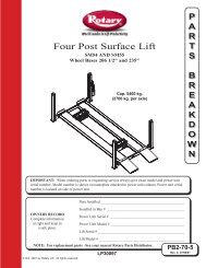
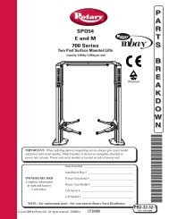
CHAPTER 2 - MACHINE DESCRIP-TION – Models - Specifications“<strong>GEMINI</strong>” models are double scissor and fixed (that isanchored to the ground) car lifts and can be delivered in bothsurface or recessed versions. They have been designed andbuilt for car, van and caravan lifting and placing operations.Our car lifts are equipped as folows (picture 3):A-BASE (Fixed structure)B-BOOMS, PLATFORM (Lifting and travelling structure).C-CONTROL BOXCAP. 2 - DESCRIZIONE DELLAMAC-CHINA Modelli - specifiche tecnicheI ponti sollevatori della serie “<strong>GEMINI</strong> ” sono a doppia forbicee fissi, cioè ancorati al suolo. Possono essere forniti siaa pavimento che ad incasso. Essi sono stati progettati ecostruiti per il sollevamento e lo stazionamento in quota diautoveicoli.I nostri sollevatori sono così composti (rif. fig. 3):A- BASAMENTO (gruppo struttura fissa).B- BRACCI - PEDANA (gruppo struttura mobile e di sollevamento).C- CENTRALINA DI COMANDO.SERIAL NUMBER / N. DI MATRICOLATRAVELLING STRUCTURESTRUTTURA MOBILENOTEAVVERTENZEFIXED STRUCTURESTRUTTURA FISSAFIXED STRUCTURE UNIT.This is the car lift base, made of steel sheet with floorfixingholes.LIFTING AND TRAVELLING STRUCTURE UNIT.This is composed of box-type steel sheet booms. The loadcarryng platform is made of steel sheet with supportinguprights anchored to the booms by steel pins at the fixedpoints, and by rollers at the movable ones. Lifting system linksare equipped with self-lubricating bushings where servicingis not required.CONTROL BOX.The unit with a metallic box that contains oil tank, pump,motor, hand pump and electro-valve sets.There are alsopower, pneumatic and hydraulic supply connections. Lowvoltagecontrols (24V) are placed on the power unit. they arethe following (picture 4):pict. - fig. 3GRUPPO STRUTTURA FISSA.E’ costituita dalla base del sollevatore, costruita in una strutturadi lamiera di acciaio sagomato con fori di fissaggio alsuolo.GRUPPO STRUTTURA MOBILE E DI SOLLEVAMENTOE’ costituita da bracci di acciaio scatolato, e dalla pedanaformata da una lamiera d’acciaio sagomata con montanti dirinforzo fissata ai bracci con perni di acciaio nei punti fissi,e con rulli nei punti mobili. Tutte le articolazioni del sistemadi sollevamento hanno boccole autolubrificanti esenti damanutenzione.CENTRALINA DI COMANDO.E’ formata da un box metallico contenente il serbatoio olio eil gruppo pompa-motore più la pompa manuale, i gruppielettrovalvole e gli attacchi per le alimentazioni elettriche,pneumatiche e oleodinamiche. I comandi sono alloggiatisulla consolle, tutti funzionano sotto tensione a 24V e sonodel tipo “uomo presente”. Essi sono i seguenti (rif. fig. 4):7
10 Keep the area under/next to the lift clear andremove possible oil spots to avoid the risk of slipping.11 Never use water-steam-varnish-solvent jets inthe lift area, and particularly, close to the controlbox.12 Proper lighting is extremely important. Makesure all areas next to the car lift are well anduniformly lie, according to that specified by theapplicable laws of the place of installation.13 Climbing on the platform when lifting the vehicleor when the same has been already raised isstrictly forbidden.14 Any use of the lift other than what herein specifiedcan cause serious accidents to the operatoras well as to the people in close proximity.15 The tampering of safety devices is strictly forbidden.16 Never exceed the maximum lifting capacity.Make sure the vehicles to be raised are withoutloads.17 In case of anomaly, stop the car lift and blockthe on/off selector by using a padlock. Only skilledtechnicians should be allowed to restart the lift.Be sure the power supply is off before repairingand servicing the lift. The operator, the lift or thevehicles raised can be seriously damaged if theseinstruction are not followed.pagliati in fase di discesa del sollevatore.10. Tenere pulita la zona vicino al sollevatorepulendo le macchie d’olio al fine di evitare pericolosiscivolamenti.11. E’ vietato usare getti d’acqua-vapore-vernicisolventinelle zone presso il sollevatore e la centralinadi comando.12. E’ rischiosa un'illuminazione non idonea.Verificare che tutte le zone siano ben illuminate edin maniera uniforme.13. E’ assolutamente vietata la presenza e “l’arrampicata”sulle pedane di persone sia durante ilsollevamento, sia a veicolo sollevato.14. E’ vietato ogni uso diverso del sollevatore daquello per cui è stato progettato, la non osservanzadi questa norma può causare incidenti anchegravi a persone e cose.15. E’ assolutamente vietata la manipolazione deidispositivi di sicurezza.16. E’ assolutamente vietato superare la capacitàmax. di sollevamento della macchina. Assicurarsiin tal senso che le vetture non siano cariche.17. In caso di comportamento anomalo del sollevatore,fermarlo e chiudere il selezionatore on/offbloccandolo con un lucchetto. Il ripristino del funzionamentodeve essere fatto da personale esperto.Prima della riparazione e manutenzione delsollevatore assicurarsi che l’alimentazione elettricasia disinserita dalla rete principale.SAFETY DEVICESANTI-SHEARING SAFETY. The lift is provided with a devicethat stops it automatically for a few seconds at approximately<strong>30</strong> cm from the floor, when the lift is lowered to point thedevice produces a warning acoustical signal.PHOTOELECTRIC SWITCH (PHOTO CELL). A special deviceto stop the lift during lowering or lifting operations wheneverthe presence of obstructions between the two platforms couldcause dangerous situations or a difference of 50 mm. existbetween the two platforms.SAFETY VALVE FOR AUTOMATIC LOWERING CUT OUT.Parachute valves able to automatically lock a single or double-actingcylinder in case a sudden increase in velocityoccurs. The valves are located inside the cilynders and preventthe load from falling down in case of sudden pipe burstingor cutting.DEAD-MAN CONTROL. The car lift is equipped with a deadmancontrol. Lowering and lifting operations are stoppedimmediately by releasing push button controls.RACK-TYPE MECHANICAL SAFETY DEVICE. A mechanicalsafety device with rack-type hooks .DISPOSITIVI DI SICUREZZASICUREZZA ANTICESOIAMENTO. Il sollevatore è fornito diun dispositivo che, in fase di discesa, lo arresta autonomamentea ca. <strong>30</strong> cm. dal suolo per alcuni secondi, emettendocontemporaneamente un segnale acustico di avvertimento.INTERRUTTORE FOTO-ELETTRICO. Trattasi di un dispositivoche blocca la discesa o la salita del sollevatore se un ostacolosi frappone fra le due pedane creando una situazione dipericolo, o rilevando un dislivello tra le due pedane di ÷ 50mm.VALVOLE DI SICUREZZA BLOCCO AUTOMATICO DISCE-SA. Il dispositivo di sicurezza è costituito da valvole (paracadute)che bloccano automaticamente i cilindri nel caso in cuila velocità di discesa aumenti in modo incontrollabile. Sonoalloggiate all’interno dei cilindri e impediscono la caduta delcarico nel caso di scoppio o taglio accidentale delle condotteoleodinamiche.SISTEMA A “UOMO PRESENTE”. Il sollevatore è dotato diun sistema operativo del tipo “uomo presente”. Le operazionidi salita-discesa (e tutte le altre operazioni) vengonoimmediatamente interrotte al rilascio dei pulsanti di comandosituati sulla consolle della centralina.SICUREZZA MECCANICA A CREMAGLIERA. Sistema meccanicodi sicurezza con agganci a cremagliera.12
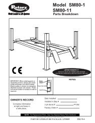
CHAPTER 4 - INSTALLATIONUNPACK THE GOODS AND CHECK FOR POSSIBLEDAMAGE BEFORE INSTALLING THE LIFT.ONLY SKILLED TECHNICIANS, APPOINTED BY THEMANUFACTURER, OR BY AUTHORIZED DEALERSSHOULD BE ALLOWED TO INSTALL THE CAR LIFT.SERIOUS DAMAGE TO PEOPLE OR EQUIPMENT CANBE CAUSED IF THIS RULE IS NOT FOLLOWED.The lift must be installed according to the specified safedistance from walls, columns, other equipments etc. The roommust be a minimum 4500 mm. in height. The minimumdistance from walls must be 1500 mm. take into considerationthe necessary space to work easily. Further space for thecontrol site and for possible runways in case of emergency isalso necessary. The lift can be placed on any floor, as long asis it perfectly level and sufficiently strong. (<strong>25</strong>0 kg/sqcm)(picture 10).INSTALLATION PROCEDURE1. Lift location.2. Power supply and pneumatic feed availability.3. Electric connections.4. Hydraulic connections.5. Electric network connection.6. Lift fixing.7. Initial running.CAP. 4 - INSTALLAZIONEPRIMA DI PROCEDERE ALL’INSTALLAZIONE DEL SOL-LEVATORE, TOGLIERE L’IMBALLO E CONTROLLARE LAMERCE.L’ INSTALLAZIONE DEL SOLLEVATORE E’ DI COMPE-TENZA DI TECNICI SPECIALIZZATI, INCARICATI DALCOSTRUTTORE O DAI RIVENDITORI AUTORIZZATI. LAMANCATA OSSERVANZA DI QUESTA NORMA PUO’CAUSARE SERI DANNI ALLE PERSONE E ALLE COSE.Il sollevatore deve essere installato rispettando le distanze disicurezza da muri, colonne, altre macchine, ecc. L’altezzaminima del locale deve essere di almeno 4500 mm. Ladistanza minima dai muri, considerando lo spazio per lavorarecomodamente, la centralina di comando e le vie di fugain caso di emergenza deve essere di almeno 1500 mm. Il sollevatorepuò essere piazzato su qualsiasi tipo di pavimento,purchè lo stesso sia perfettamente piano e di resistenza adeguata(min. <strong>25</strong>0 kg.x cmq.) (rif. fig. 10)PROCEDURA DI INSTALLAZIONE.1) Posizionamento del sollevatore.2) Verifica disponibilità alimentazioni elettriche e pneumatiche.3) Connessioni elettriche.4) Connessioni oleodinamiche.5) Allacciamento rete elettrica.6) Fissaggio sollevatore.7) Primo avviamento.1) LOCATION OF THE LIFT1) POSIZIONAMENTO DEL SOLLEVATORE.min.1500h 4500 min.70 cmP1P2max2000min.800TO OPENPER APRIRETO MOVEPER SPOSTAREpict. - fig. 10Place the automotive lift using a crane truck or any other liftingequipment. Raise the two platforms using a crane, placethem at a height of about 70 cm. (to open) and make sure themechanical safety devices are on. Move the car lift, sling it asdescribed in picture 10 and adjust the distance between thetwo platforms so that they are exactly parallel. After havingset the location of the lift, it may be necessary to level the unitwith metallic shims under the base.Posizionare il sollevatore con l’aiuto di un carro ponte o altromezzo di sollevamento adeguato nel punto desiderato.Sollevare (per aprire il sollevatore) con una gru le due pedaneseguendo le indicazioni in figura per una altezza di ca.70 cm. assicurandosi che le sicurezze meccaniche sianoinserite. Per spostare il sollevatore imbracarlo come in figura10 e posizionarlo a dovere. Procedere all’eliminazione dipiccoli dislivelli del suolo servendosi di spessori metallici.13
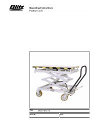
2) POWER SUPPLY AND PNEUMATIC FEED AVAI-LABILITY CONTROLThe room must be previously arranged for the power supplyand pneumatic feed of the lift. Make sure that supplies arenot far from the power unit.3) ELECTRIC CONNECTIONSConnect the lift cables (see picture 11) to the relative connectorsplaced within the electric card of the power unit (picture12).2) VERIFICA DISPONIBILITA’ ALIMENTAZIONEELETTRICA E PNEUMATICA.Il locale deve essere preventivamente predisposto per l’alimentazioneelettrica e pneumatica del sollevatore.Assicurarsi che gli attacchi per tali alimentazioni sianodisponibili nei pressi della centralina.3) CONNESSIONI ELETTRICHE.Collegare i cavi numerati provenienti dal sollevatore, (vedifig. 11) ai connettori corrispondenti situati nella scheda elettricaall’interno della centralina di comando (rif. fig. 12).4 2153 6pict. - fig. 11Pos. N. Code Description1 06-0<strong>30</strong>2 Lifting limit switch2 06-0<strong>30</strong>2 Photoelectric cell cut out3 06-0<strong>30</strong>2 P2 platform self levelling4 06-6606 Photoelectric cell nc5 06-0<strong>30</strong>2 P1 platform self levelling6 06-6603 ReflectorN. indiv. Codice Descrizione1 06-0<strong>30</strong>2 Fine corsa alto2 06-0<strong>30</strong>2 Esclusione fotocellula3 06-0<strong>30</strong>2 Autolivellamento pedana p24 06-6606 Fotocellula NC5 06-0<strong>30</strong>2 Autolivellamento pedana p16 06-6603 Catarifrangente14
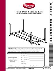
ELECTRIC CARD CONNECTIONSCOLLEGAMENTO ELETTRICO SULLA SCHEDA(24 VAC)(EA)(SA)(CM)15 2TOUCH PADCONNETTORE PULSANTIERA71 5 2(+) BLKAK (-)NEROBROWNNMARRONEBLLUBLU43(EL)(EO)43pict. - fig. 12EOELCMEASA12345Lowering oil electrovalveLevelling electrovalveMotor contactorAir electrovalveMotor saverLifting limit switch proximetryPhotocell exclusion proximetryP2 platform levelling proximetryPhotocellP1 platform levelling proximetryEOELCMEASA12345Elettrovalvola olio discesaElettrovalvola livellamentoContattore motoreElettrovalvola ariaSalvamotoreProximetri fine corsa altoProximetri esclusione fotocellulaProximetri per livellamento pedana P2FotocellulaProximetri per livellamento pedana P1WIRING DIAGRAMSCHEMA DI CONNESIONE ELETTRICAFUSE10X38 20 AA1CMA2MFUSE5X20 1 A0220380024pict. - fig. 1315
ELECTRIC CARDSCHEDA ELETTRICA24V ACSALVAMOTORPRE. GPL7EAGEMIM.GEMEAGLPFCALTO1FCLIV.P15FC.EFOT.2PULSANTC1C2IC1C3R2JP1F1JP4K6JP5DLGJP4JP16DLMGJP4DLEGJP9JP11JP10K1C20S1C1C1DL1DL4K4 (T1)K7K16 (T4)K10 K9 K8K13K11K12K2K3K17K14D23K15 (T3)C17S2IC4DL1K5 (T2)D31JP17IC5DLDDLFJP14ELEOGEMIJP134FOTJP124FCLIV.P2SIRpict. - fig. 14JP1/17D1/37DLS1IC4C1/24IC 1-2-3-5K1/17R1/44SIRS2IC5TR1/5F1CONNECTORSDIODSLEDRESET TIMER BUTTONTIMER MICROCHIPCAPACITORVOLTAGE STABILIZERRELAISRESISTORSBLEEPERTIMER REGULATORBLEEPER MICROCHIP TIMERTRANSISTORSFUSEJP1/17D1/37DLS1IC4C1/24IC 1-2-3-5K1/17R1/44SIRS2IC5TR1/5F1CONNETTORIDIODILEDPULSANTE RESET TIMERTIMER MICROCHIPCONDENSATORISTABILIZZATORIRELERESISTENZECICALINOREGOLAZIONE TIMERMICROCHIP TIMERTRANSISTORSFUSIBILE 5x20 4ATIMER - S2 - ON THE ELECTRIC CARDTIMER - S2 - SU SCHEDA ELETTRICATIMERS ADJUSTMENT - REGOLAZIONE TIMER -S2-12 11 10 9 8 7 6 5 4 3 2 1NO"T1" STOP TIME FOR LOWERINGADJUSTMENT - REGOLAZIONE TEMPO DI ARRESTO DISCESA2 12 12 12 1NO2 SECNO4 SECNO5 SECNO6 SEC"T2" P2 PISTON PREELUDING TIME ADJUSTMENT - REGOLAZIONE TEMPO DI PRECARICA PISTONE4 34 34 34 3NO0,5 SECNO1 SECNO1,5 SECNO2 SEC"T3" TIMER LIFTING TIMER BEFORE THE ACTION ADJUSTMENT - REGOLAZIONE TEMPO DI SALITA PRIMA DELLA DISCESA7 6 57 6 57 6 57 6 5NO2 SECNO3 SECNO4 SECNO6 SECpict. - fig. 1516
4) HYDRAULIC CONNECTIONS4) CONNESSIONI OLEODINAMICHEAIR ELECTROVALVEELETTROVALVOLA ARIAEU1R1EER2LOWERING ELECTROVALVEELETTROVALVOLA DISCESAAFP2DP1CBEACLEVELLING ELECTROVALVEELETTROVALVOLA LIVELLOBpict. - fig. 16ABCDEFP1 DELIVERYDISCHARGELEVELLING-P2 DELIVERYP1 DISCHARGE-P2 DELIVERYP2 DELIVERYP2 DISCHARGEABCDEFMANDATA P1SCARICOAUTOLIVELLAMENTO - MANDATA P2SCARICO P1 - MANDATA P2MANDATA P2SCARICO P2HYDRAULIC PLANSCHEMA IMPIANTO OLEODINAMICOP1P21 121039547 M68pict. - fig. 1712345678910Parachute valveLevelling electro valve (el)Lowering electro valve (eo)Flow regulator valveFull force valve5l. pumpThree phase motor 4 hpSuction filterHand pumpUnidirectional valve12345678910Valvola paracaduteElettrovalvola di livellamento (EL)Elettrovalvola di discesa (EO)Valvola regolatrice di flussoValvola di massimaPompa 5 litriMotore trifase 4 HPFiltro di aspirazionePompa a manoValvola unidirezionale17
PNEUMATIC CONNECTION DIAGRAMSCHEMA DI COLLEGAMENTO PNEUMATICO196876423454pict. - fig. 18123456789Main supplyControl boxAir electro valve“Rilsan” white air pipeTee-piece unionPneumatic jack for mechanical Safety releaseP 1 platformP 2 platformAir filter and lubricator123456789Entrata rete pneumaticaCentralina di comandoElettrovalvola ariaTubo aria “rilsan” biancoRaccordo a “T” rap.Pistoncino sicurezza meccanicaPedana P 1Pedana P 2Gruppo filtro e regolazione aria5) ELECTRIC SYSTEM CONNECTIONWarning ! Only skilled personnel should be allowedto perform the operation shown below.Connect as follow:• Open the control box front cover and using the terminals37-40 (picture 26), connect the electric cable to the generalswitch cable (be sure that the cable passes trought the properspace located behind the control box). Before connectingthe electric system, make sure that the power supply plant tothe lift is equipped with the protection devices required bycurrent standards in the country where the lift is installed.Connect the lift cables to the relative cables placed within theelectric card as spescified on page 12, and make sure thatthe connections are correct. (Refer to pictures 12,13 and 14).BE CAREFULBefore accessing inside the control box, for connectionto the power or for the repair of electric equipmentsbreakdown, make sure that the main power supply isdisconnected, to avoid the possibility of electrocution.5) ALLACCIAMENTO RETE ELETTRICAAttenzione: Le operazioni sottoelencate devono essereeseguite da personale qualificato.Eseguire l’allacciamento di potenza alla centralina di comandocome segue:• Aprire il coperchio della centralina e allacciare, mediantei morsetti (37-40 rif. fig. 26), il cavo di alimentazione elettricaal cavo collegato all’interruttore generale, facendo passareil cavo di alimentazione nell’apposito spazio situato nelretro della centralina. Assicurarsi che la linea di alimentazioneelettrica sia adeguatamente protetta da interruttoremagnetotermico con capacità e caratteristiche adeguate econforme alle normative vigenti di sicurezza.• Allacciare i cavi provenienti dal sollevatore alla morsettieradella scheda elettrica secondo le indicazioni date nellafigura 12 riguardante le connessioni elettriche, verificarequindi che le connessioni siano state eseguite nel modo corretto(rif. fig. 12/13/14).ATTENZIONE!Prima di agire all’interno della centralina di comando,per l’allacciamento alla rete elettrica o per la riparazionedi un guasto agli apparati elettrici, assicurarsi chel’alimentazione elettrica principale sia disinserita evitandocosì la pericolosa possibilità di folgorazione.18
COMMERCIAL PARTS - WIRING PLANT (Refer to pictures 11-26)PARTICOLARI COMMERCIALI IMPIANTO ELETTRICO (rif. fig. 11-26)N.pos.1-23-54243936<strong>35</strong>3414DenominationProximityPhotoelectric cellGeneral switchTouchpadFuse holder (3)FuseContactorTransformerElectric cardManufacturerSIEMENSSELETSprecher SchuhTASTITALIAWEBERWEBERSIEMENS / GE /AR / SSLSPROTARY LIFTType10..<strong>30</strong>V DC pnp NC0’3A-Sn1=2mm.18-12M/pnp NC24V-L3-32-1753 16AD.ROTARY LIFT32A-690VVari16A - 18A70VAD.ROTARY LIFTMax ApplicationN.pos.1-23-54243936<strong>35</strong>3414DenominazioneFinecorsa diprossimità induttiviFotocellulaInterruttore generaleTastieraPorta fusibili 3FusibiliContattoreTrasformatoreScheda elettricaCostruttoreSIEMENSSELETSprecher SchuhTASTITALIAWEBERWEBERSIEMENS / GE /AR / SSLSPROTARY LIFTTipo10..<strong>30</strong>V DC pnp NC0’3A-Sn1=2mm.18-12M/pnp NC24V-L3-32-1753 16AD.ROTARY LIFT32A-690VVari16A - 18A70VAD.ROTARY LIFTMax. utilizzoPNEUMATIC SYSTEM (Refer to pictures 18)IMPIANTO PNEUMATICO (rif. fig. 18)N.pos.<strong>35</strong>469DenominationAir ElectrovalvePneumatic connectionsPneumatic pipeAir pistonAir filterManufacturerACL/MMVARIORILSANROTARY LIFTAIRSISTEMType24V~50/60 HZ 8VAVARIOØ 4x6FR+L 1/4Max Application10 Bar16 Bar<strong>30</strong> Bar15 Bar-N.pos.<strong>35</strong>469DenominazioneElettrovalvola ariaRaccordi pneumaticiTubo pneumaticoPistoni ariaGruppo filtro/regolazione ariaCostruttoreACL/MMVARIORILSANROTARY LIFTAIRSISTEMTipo24V~50/60 HZ 8VAVARIOØ 4x6FR+L 1/4Max. utilizzo10 Bar16 Bar<strong>30</strong> Bar15 Bar-HYDRAULIC SYSTEM (Refer to pictures 17-26)IMPIANTO IDRAULICO (rif. fig. 17-26)N.pos.1712<strong>25</strong>10953291P1P24DenominationCover TankTankFilterPumpMotorMax pressure valveLowering electrovalveLevelling electrovalveHand pumpParachute valveP1 PistonP2 PistonR1 Hydraulic pipeR2 Hydraulic pipeCrimp fittingHydraulic connectionFlow regulatorManufacturerROTARY LIFTROTARY LIFTFBNHYDROIRMAELPROM/ELDTECNORDTECNORDTECNORDTECNORDMONTIROTARY LIFTROTARY LIFTMANULIMANULIVARIVARITECNORDType---UP10K163 MOD.291220/380-3PM-50HZ1400 RPM 3KW 4HP IP5424AC 50HZ 20W89.01.952.1.9Ø110 x Ø 45 x L560Ø100 x Ø 45 xL 560VARIOVARIOVARIOVARIOVRC 10/11Max Application<strong>25</strong>0 Bar85/220 Bar<strong>25</strong>0 Bar<strong>25</strong>0 Bar<strong>30</strong>0 Bar<strong>30</strong>0 Bar210 Bar400 Bar400 Bar400 Bar2<strong>30</strong> BarN.pos.1712<strong>25</strong>10953291P1P24DenominazioneCoperchio serbatoioSerbatoioFiltroPompaMotoreValvola max pressioneElettrovalvola discesaElettrovalvolalivellamentoPompa a manoValvola paracadutePistone P1Pistone P2Tubo Idraulico R1Tubo idraulico R2Raccordi idraulicia pressareRaccordi idrauliciValvola controlloregolatrice di flussoCostruttoreROTARY LIFTROTARY LIFTFBNHYDROIRMAELPROM/ELDTECNORDTECNORDTECNORDTECNORDMONTIROTARY LIFTROTARY LIFTMANULIMANULIVARIVARITECNORDTipo---AP100/5-D-319220/380-3PM-50HZ1400 RPM 3KW 4HP IP5424AC 50HZ 20W89.01.952.1.9Ø110 x Ø 45 x L560Ø100 x Ø 45 xL 560VARIOVARIOVARIOVARIOVRC 10/11Max. utilizzo<strong>25</strong>0 Bar85/220 Bar<strong>25</strong>0 Bar<strong>25</strong>0 Bar<strong>30</strong>0 Bar<strong>30</strong>0 Bar210 Bar400 Bar400 Bar400 Bar2<strong>30</strong> Bar6) LIFT FIXINGAfter making electric and hydraulic connections (refer topictures 16,17,28), make sure they are properly connected.Now fix the lift to the floor, using the bases as templates,drill a hole into the floor a 16 mm.Ø bit must be usedup to a depth of about 150 mm., clean the holes, place theproper inserts with light hammer blows and finally tighten6) FISSAGGIO SOLLEVATOREDopo aver eseguito i collegamenti elettrici ed oleodinamici(rif. fig. 16/17/28), assicurarsi che gli stessi siano effettuatiin modo corretto e che le due basi del sollevatore sianoperfettamente parallele. Fissare quindi il sollevatore alsuolo e, usando le basi come dime, forare con una puntada Ø 16 mm. il pavimento per una profondità di ca. 15019
the bolts. In case of an inground lift check it is perfectly centred.(To open the lift see chapter “4” INSTALLATION).7) FIRST STARTINGWarning! Only skilled and authorized personnelshould be allowed to perform these operations.Carefully follow all instructions shown below to preventpossible damage to the car lift or risk of injuryto people.Be sure that the operating area is cleared of people.After positioning the lift as specified, and performing electricand hydraulic connections (do not perform pneumaticconnection yet) the lift can be operated by the proceduresshown below: Open the front door of the control box andunscrew the oil tank cap (pos.11, picture 26), and using afunnel pour about 13 l. of ISO 32 hydraulic oil or equivalent.Move the master switch to “1” position (pos.6, picture4) and simultaneously press “lifting” and “limit switchcut out” push buttons (see picture4, pos. 1-4) keep thempressed until the P1 is fully lifted . If motor rotates but liftingoperations cannot be performed, check motor for properdirection of rotation, change the phases if necessary. Add.5 l. of oil in the tank and press again the two buttons untilthe P2 platform is fully lifted . Perform the pneumatic connectionnow To lower the car lift, press the “lowering” button.(picture4, pos.2). Repeat lifting/lowering operationsthree or four times to bleed air from the cylinders.mm., pulire i fori ed inserire i tasselli adeguati con leggericolpi di martello, serrare quindi i bulloni terminando leoperazioni. Nel caso di posizionamento ad incasso del sollevatore,verificare attentamente che lo stesso sia perfettamentecentrato nelle proprie sedi. (Per aprire il sollevatorevedere indicazioni al cap. “4” INSTALLAZIONE).7) PRIMO AVVIAMENTOAttenzione! Tutte queste operazioni devono essereeseguite da personale esperto ed autorizzato.Seguire attentamente le indicazioni al fine di evitaredanni alle persone e al sollevatore.Assicurarsi che l’area di rischio sia deserta.Dopo aver posizionato il sollevatore come descritto ed avereffettuato i collegamenti elettrici ed idraulici (non eseguireper ora il collegamento pneumatico), si può procedere alleoperazioni necessarie per il funzionamento del sollevatore.Aprire lo sportello anteriore della centralina di comando esvitare il tappo del serbatoio olio (pos. 11 fig. 26), con unimbuto introdurre 13 litri di olio idraulico “ISO 32”. Portarel’interruttore generale in posizione “1” (pos. 6 fig. 4) e premerecontemporaneamente il pulsante di salita e il pulsantedi esclusione (pos. 1-4 fig. 4) fino alla salita completadella pedana P1. Se il sollevatore non si muove ma il motore,gira regolarmente, assicurarsi che lo stesso abbia il giustosenso di rotazione, nel caso contrario invertire le fasisulla linea di alimentazione elettrica. Introdurre altri 5 LT. diolio nel serbatoio e premere nuovamente i due pulsanti finoalla salita completa della pedana P2. Eseguire ora il collegamentopneumatico (rif. fig. 18-28). Per far scendere ilsollevatore premere il pulsante di discesa (pos. 2 fig. 4).Eseguire le operazioni di salita/discesa per quattro/cinquecicli per eliminare eventuali depositi di aria nei cilindri concludendole operazioni (spurgo).20
CHAPTER 5 - OPERATIONDRIVING SEQUENCECAP. 5 - FUNZIONAMENTOSEQUENZA DI FUNZIONAMENTOpict. - fig. 19Be sure the platforms are fully closed before getting on/offthe lift. Get in the vehicle and drive on the lift; be sure thevehicle is centred and both rear and front wheels are properlypositioned, place the proper rubber pads on theplatform (picture 19) so that they are in line with the liftingpoints specified by the manufacturer. Press the “lifting” button,keepit pressed until the required height is reached and,ethen press the “mechanical safety” button to engage mechanicalsafety mechanism (picture 4, pos.3). To lower the lift,press the “lowering” button (picture 4, pos.2), when this buttonis pressed a short lifting movement occurs so that themechanical safety devices can be disengaged. During thelowering phase, the lift will stop automatically for someseconds at approximately <strong>30</strong> cm. from the floor, producing asafety acoustic signal, so the lift lowers again.During the first hours of operation cracking noises couldoccur. This is due to the natural settlement of mechanicalparts and will disappear during the following hours of operation.CHECKSPerform the following checks when operating the car lift:• Be sure that mechanical safety devices are properlyinserted in their seats.• Carefully check the car lift and its load duringlifting/lowering operation.• Check the warning acoustic signal of the car lift duringlowering operation.Prima di salire/scendere con l’autovettura dal sollevatore,assicurarsi che le pedane siano completamente chiuse. Salirecon l’autovettura sul sollevatore molto lentamente assicurandosiche la stessa sia ben centrata sulle pedane.Piazzare gli appositi tamponi in gomma sulla pedana delsollevatore (vedi fig. 19) rispettando i punti di sollevamentoconsigliati dal costruttore dell’autovettura. Premere il pulsantedi “salita” e portare il sollevatore all’altezza desideratapremendo successivamente il pulsante di “stazionamento”(fig.4 pos.3). Per la discesa, Premere il pulsante “discesa”(fig. 4 pos 2), premendo questo pulsante il sollevatore sialzerà quanto basta per disinserire le sicurezze meccaniche.Durante la fase di discesa il sollevatore si fermerà automaticamenteper alcuni secondi a ca. <strong>30</strong> cm. dal suolo emettendoun segnale acustico di sicurezza, quindi riprenderà ladiscesa.Nelle prime ore lavorative del sollevatore, potrebbero verificarsirumori o cigolii dovuti al non ancora avvenuto assestamentonaturale delle parti meccaniche, questo inconvenientesparirà da solo nelle successive ore lavorative delsollevatore.CONTROLLIEseguire i seguenti controlli durante il funzionamento del sollevatore:• Osservare che le sicurezze meccaniche abbiano un correttoinserimento nella loro sede.• In fase di salita/discesa osservare costantemente il sollevatoree il suo carico.• Controllare il funzionamento del segnale acustico diavvertimento nell’ultima fase di discesa del sollevatore.21
CHAPTER 6 - MAINTENANCEWARNING! Only skilled and previously authorized personnelshould be allowed to service the lift. When servicingthe lift, all safety precautions must be followed to avoid accidentalstarting of the machine. The master switch must bepadlocked in “zero” position. The key should be kept by themaintenance technician throughout the service. During serviceoperations,all safety instructions reported in chapter 3,“SAFETY”, must always be followed.PERIODIC MAINTENANCEMaintenance operations must be performed at each specifiedmaintenance period in order to keep the car lift in perfectworking condition. The manufacturer is not liable for possibledamage resulting from failure to follow the above instructions.• Car lift must be cleaned once a month, at least, withoutusing chemical agents and hight pressure washing guns.Always dispose of used brake oil to prevent possibledamage to the finish. Carefully check that piston rods arenot damage sinced inside gaskets and seals could beseriously damaged and leakage of oil occur.• Check safety devices for proper working condition periodically.• Grease roller slideways periodically.• Check flexible tubes for proper conditions yearly.• Change hydraulic system oil at 5 year intervals, at least.Used oil is a highly pollutant product. Always dispose ofused oil as specified by the effective law of the countrywhere the car lift is installed.MACHINE DEMOLITIONWhen demolishing the machine all safety precautions specifiedin chapter “3”-”4” must be followed. Only authorizedtechnicians should be allowed to perform this operation.Metallic parts can be scrapped as “scrap iron”. In any case,demolished material must be eliminated according to theeffective laws of the country where the car lift is installed. Itmust be remembered that, for fiscal purposes, any demolitionoperation must be properly documented as specified by theeffective laws of the country where the lift is installed at thetime of demolition.CAP. 6 - MANUTENZIONEATTENZIONE! La manutenzione deve essere affidataesclusivamente al personale autorizzato. Durante la manutenzionedel sollevatore è necessario adottare tutti i provvedimentiutili per evitarne l’avviamento accidentale.L’interruttore generale deve essere bloccato in posizione “0”mediante lucchetto. La chiave deve essere custodita dalmanutentore per tutta la durata dell’intervento. Ovviamentebisogna rispettare tutte le indicazioni e gli obblighi riportatinel capitolo “3” SICUREZZA.MANUTENZIONE PERIODICA.Per mantenere il sollevatore in piena efficienza, è necessariorispettare le tempistiche di manutenzione indicate. Il mancatorispetto di quanto sopra solleva il costruttore da qualunqueresponsabilità agli effetti della garanzia.• Il sollevatore deve essere pulito almeno una volta al mesenon usando aggressivi chimici e pistola ad acqua ad altapressione. Attenzione all’olio dei freni, se non viene subitoeliminato rischia di rovinare irrimediabilmente la verniciatura.E’ importante che lo stelo dei pistoni vengapreservato da eventuali impurità che potrebbero danneggiarlo,ciò potrebbe portare ad un’usura prematurao peggio ad una rottura delle guarnizioni interne causandouna pericolosa perdita di olio.• Controllare periodicamente lo stato degli apparati di sicurezza.• Lubrificare periodicamente con grasso le guide di scorrimentorulli.• Controllare annualmente lo stato dei tubi flessibili ad altapressione.• Cambiare l’olio dell’impianto idraulico almeno ogni 5anni. Si consiglia di integrare l’impianto pneumatico conun gruppo trattamento aria. L’olio esausto che vieneestratto dall’impianto durante il cambio d’olio, deveessere trattato come prodotto inquinante, pertanto dovràessere smaltito secondo le prescrizioni della legislazionevigente nel paese in cui è stato installato il sollevatore.DEMOLIZIONE DELLA MACCHINA.Durante la demolizione della macchina devono essere osservatetutte le precauzioni di sicurezza adottate nei capitoli“3”, “4”. La demolizione della macchina deve essere effettuatada tecnici specializzati come per il montaggio. Le partimetalliche possono essere rottamate e catalogate come rottamiferrosi. In ogni caso tutti i materiali derivati dalla demolizionedevono essere smaltiti in accordo alla normativa vigentenel paese in cui il sollevatore è installato. Si ricorda che aifini fiscali, occorre documentare l’avvenuta demolizione producendodenunce e documenti secondo la legislazione vigentenel paese di installazione del sollevatore.22
CHAPTER 7 - TROUBLESHOOTINGTroubleshooting and possible repairs requireabsolutecompliance with all safety precautions indicated in chapters3 and 6.MANUAL LOWERINGCAP. 7 - INCONVENIENTI E RIMEDILa ricerca dei guasti e gli eventuali interventi di riparazionerichiedono il rispetto di tutte le precauzioni di sicurezzaindicate al cap. “3” ed al cap.”6”.DISCESA MANUALEMANUAL PUMP / POMPA MANUALELOWERING E.V.ELETT. VALVOLA DISCESAMANUAL OPERATOROPERATORE MANUALEMAX PRESSUREVALVEVALVOLA DIMASSIMALEVELLING E.V.ELETT. VALVOLALIVELLOfig. 20 pict. - fig. 21To lower the platforms, raise the lift with the hand pumpabout 2cm. in order to disengage the mechanical safety devices.Lift the mechanical safety pawls using a wooden shim ofabout 3cm and place it along the rack (picture 20).With a“5” hexagonal key, unscrew very slowly the hand loweringvalve (manual operator, picture 21), carefully following thelift lowering. When the lift is fully lowered, screw the handlowering valve. Once the trouble has been repaired, raisethe lift and remove the wooden shims.TROUBLESHOOTINGSYMPTOM 11) The lifting button is pushed but the lift does not move (themotor does not run)POSSIBLE CAUSE 1:1A) Lack of electric feed on the electric card and on the transformer.(pos. 34, 14 picture 26)REMEDY - Check the relative fuse. In case of blownfuse, replace them (pos. 41, 36 picture. 26)1B) Malfunctioning touchpad.REMEDY - Check the touchpad with a tester and replaceit if faulty.1C) Difective electric card.REMEDY - Check whether the relays and leds are activatedby pushing the buttons on the touchpad. (pos. DLpicture14).1D) Uncertain connections between the electric card and thePer far scendere le pedane, alzare con la pompa a mano ilsollevatore un paio di cm. per dare la possibilità alle sicurezzemeccaniche di disinserirsi, alzare gli arpioni della sicurezzameccanica con una tavoletta di legno spessa ca. 3 cm.e posizionarla per tutta la lunghezza della cremagliera (vedifig. 20)., con una chiave esagonale da “5” svitare lentamentela valvola di discesa manuale (operatore manuale rif. fig.21) prestando attenzione alla discesa del sollevatore, quandoil sollevatore sarà arrivato a terra riavvitare la valvola.Riparato il guasto, alzare il sollevatore e togliere lo spessorein legno dalla sicurezza meccanica.DIAGNOSTICASINTOMO 11) Pulsante di salita premuto ed il ponte rimane fermo (ilmotore non gira)PROBABILE CAUSA 1:1A) Mancanza di alimentazione elettrica su scheda e su trasformatore(pos. 34, 14 fig. 26)RIMEDIO - Controllare l’efficienza dei relativi fusibili.Qualora fossero saltati verificare la causa del cortocircuitoe sostituire i fusibili (pos. 41, 36 fig. 26)1B) Mal funzionamento del TUCH PAD.RIMEDIO - Controllare tramite tester, sui puntalini, lafunzionalità del TUCH PAD sostituendolo se guasto.1C) Scheda guasta.RIMEDIO - Controllare se premendo i pulsanti del23
contactor; motor protector; valves (see picture 12-21)REMEDY- Check the connections between the electriccard and the contactor; the motor protector; the valves.Replace any faulty parts.1E) Malfunctioning photocell (picture 11-12)REMEDY - Check that the photocell and its connectionsare correct. Replace the photocell if faulty.1F) Malfunctioning lifting limit switch (picture 11-12)REMEDY - Check the lifting limit micro and make surethe connections are correct. Replace it if faulty.SYMPTOM 22) The lifting button is pushed but the lift does not move (themotor runs)POSSIBLE CAUSE 2:2A) Counterclockwise rotationREMEDY - Verify and switch the phase of the motor ifnecessary.(pos. 37 picture.26).2B) Lack of oilREMEDY - Check that there is enough oil in the tank.2C) The manual operator (OM) for the lowering, placed onthe hydraulic block, is open (picture 21).REMEDY- Close the OM with a 5mm hexagonal wrench.2D) The lowering elecrovalve on the hydraulic block,remainsopen. (picture 21)REMEDY - Check whwther it is open because of amechanical fault or because it is excited by the magnet.Replace the faulty parts.2E) The max. pressure valve isnot calibrated or broken (picture21)REMEDY- Tighten the valve fully and then backoff 11/2 turns.Retest the lift and replace the valve if the problemreoccurs.2F) The flexible hose connecting the pump and the hydraulicblock broken or loose (pos. 22 picture. 26)REMEDY- Check the hose placed in the tank. Replaceit if broken.SYMPTOM 33) The lowering button is pushed but the lift does not movePOSSIBLE CAUSE 3:3A) Check as in step 1, lifting limit switch excluded.REMEDY - Follow the instructions for remedies indicatedin step 1SYMPTOM 44) The lowering button is pushed, the lift raises a little bitand then stops.POSSIBLE CAUSE 4:4A) The lowering ekectrovalve relains closed (see picture21).REMEDY - Check whether the electrovalve is closedbecause of a mechanical fault or because it is not excitedby the magnet. Replace the faulty parts.4B) The parachute valve is blocked (pos. 22 picture 24).TOCH PAD vengono attivati i rele e led presenti sullascheda (pos. DL fig. 14).1D) Collegamenti incerti tra la scheda ed il contatore; salvamotore;valvole, (vedi fig. 12-21)RIMEDIO - Controllare e verificare le connesioni tra lascheda ed il contatore; il salvamotore, le valvole.Sostiture eventuali parti danneggiate1E) Mal funzionamento della fotocellula (vedi fig. 11-12)RIMEDIO - Controllare e verificare che la fotocellula ei suoi collegamenti siano corretti. Sostituire la fotocellulase guasta.1F) Mal funzionamento del micro di fine corsa (vedi fig. 11-12)RIMEDIO - Controllare e verificare il micro di finecorsa alto e che i suoi collegamenti siano corretti.Sostituirlo se ritenuto guasto.SINTOMO 22) Pulsante di salita premuto ed il ponte rimane fermo(motore non gira)PROBABILE CAUSA 2:2A) Rotazione del motore al contrarioRIMEDIO - Verificare ed eventualmente invertire le fasidi alimentazione della corrente al motore (pos. 37fig.26).2B) Manca olioRIMEDIO - Controllare che nel serbatoio ci sia olio asufficienza.2C) Operatore manuale (OM) per la discesa, sul bloccoidraulico, è aperto (vedi fig.21)RIMEDIO - Chiudere l’operatore manuale con unachiave esagonale da 5 mm..2D) Elettrovalvola olio discesa, sul blocco idraulico, rimaneaperta. (vedi fig. 21)RIMEDIO - Controllare se l’elettrovalvola è rimastaaperta per un guasto meccanico o perché eccitata dalmagnete. Sostituire le parti guaste.2E) Valvola di MAX pressione starata o rotta (vedi fig. 21)RIMEDIO - Avvitare completamente la valvola e fare 1giro e 1/2 in dietro, riprovare il ponte, se il problemasussiste sostituire la valvola.2F) Tubo flessibile di collegamento pompa-blocco idraulico,rotto o lenta (pos. 22 fig. 26)RIMEDIO - Controllare il tubo che alloggia nel serbatoio.Sostituire se rotto.SINTOMO 33) Pulsante di discesa premuto ed il ponte rimane fermo.PROBABILE CAUSA 3:3A) Verificare come dal punto 1 escluso fine corsa alto.RIMEDIO - Seguire le indicazioni d’intervento indicatenelle cause indicate al punto 1SINTOMO 44) Pulsante di discesa premuto ed il ponte sale un po e poisi ferma.24
REMEDY - Raise the lift at some centimetersheight and repeat the lowering phase. If theproblem occurs again, pull the parachute valves out ofthe pistons, adjust their opening ranging from 0,<strong>35</strong>-0,40 mm. or replace them if damaged.4C) The mechanical safeties are closed due to a faulty airelectrovalve (pos. 3 picture18).REMEDY - Check whether the air electrovalve, releasingthe mechanical safety , is closed because of amechanical fault or because it is not excited by themagnet. Replace the faulty parts. Verify that theworking air pressure is 5 bar min. (pos. 5-16 picture.26).SYMPTOM 55) Pulsante di salita premuto il ponte si ferma durante lasalita.POSSIBLE CAUSE 55A) If pushing both the yellow exclusion button and the liftingbutton, the lift moves: the lifting limit switch is faultyor incorrectly positioned (pos. 1 picture 14)REMEDY - Check the correct position of the cam andthe functioning of the micro switch . Replace it if faulty.(The micro should intercept the cam when the pplatformis at the max. height indicated in pictures 6, 7, 8).5B) If pushing both the yellow exclusion button and the liftingbutton, the lift does not moveREMEDY- Check the instructions in step 1SYMPTOM 66) During the lowering phase, the acustic signal starts beeping(but the lift is not at <strong>30</strong> cm from the floor yet).POSSSIBLE CAUSE 6:6A) The microswitch for thr photocell cot out is faulty orincorrectly positioned. (pos. 2 picture 11).REMEDY - Check the correct position of the cam or thrfunctioning of the micro. Replace it if faulty. (The microshould intercept the cam when the platform is at about<strong>30</strong> cm from the floor).SYMPTOM 77) The P1 platform is fully lowered while the P2 platformremains lifted.POSSIBLE CAUSE 7:7A) The levelling valve remains closed due to : (see picture21). The P1 levelling microswitch is positioned incorrectly.(pos. 5 picture 11)REMEDY - Check the correct position of the miscroswitchon its support. Replace the micro if faulty.7B) The magnet of the levelling valve is not excited.REMEDY - Check whether the valve opens by connecting24V directly on the magnet. Check the functioningof the electric card and the connection of the cablebetween the magnet and the card.7C) The levelling valve on the hydraulic block remains closed(see picture 21)REMEDY - Check whether the elkectrovalve is blocked.PROBABILE CAUSA 4:4A) Elettrovalvola controllo discesa rimane chiusa, (vedi fig.21).RIMEDIO - Controllare se l’elettrovalvola è rimastachiusa per un guasto meccanico o perché non eccitatadal magnete. Sostituire le parti guaste.4B) Valvola para cadute bloccata, vedi (pos. 22 fig. 24).RIMEDIO - Far salire per alcuni centimetri il ponte eripetere l’operazione di discesa, se l’inconveniente siripete estrarre le valvole paracadute dai pistoni, registrarlecon un’apertura compresa tra 0,<strong>35</strong>-0,40 mm. osostituirle se danneggiate.4C) Sicurezze meccaniche chiuse a causa del mal funzionamentodell’elettrovalvola aria, vedi (pos. 3 fig. 18).RIMEDIO - Controllare se l’elettrovalvola aria, sganciosicurezze meccaniche, è rimasta chiusa per un guastomeccanico o perché non eccitata dal magnete. Sostituireeventuali parti guaste. Controllare che la pressione d’eserciziosia sufficiente “min. 5 bar” (pos. 5-16 fig. 26).SINTOMO 55) Pulsante di salita premuto il ponte si ferma durante lasalita.PROBABILE CAUSA 55A) Se con il pulsante giallo di esclusione ed il pulsante disalita contemporaneamente premuti il ponte si muove:micro si fine corsa alto guasto o non correttamente posizionato,(pos. 1 fig. 14)RIMEDIO - Controllare l’esatta posizione della cammao la funzionalità del micro. sostituire se ritenuto guasto.(il micro deve intercettare la camma quando la pedanasi trova ad un’altezza max indicata a FIg. 6, 7, 8).5B) Con i pulsanti: giallo di esclusione e di salita, premuticontemporaneamente, il ponte non si muove.RIMEDIO - Controllare i passaggi del punto 1.SINTOMO 66) Durante la discesa del ponte il segnalatore acustico iniziaa segnalare (ma non è ancora arrivato a <strong>30</strong> cm. daterra).PROBABILE CAUSA 6:6A) Il micro di esclusione fotocellula guasto o non correttamenteposizionato. (pos. 2 fig. 11).RIMEDIO - Controllare l’esatta posizione della cammao la funzionalità del micro. Sostituire se ritenuto guasto.(il micro deve intercettare la camma quando la pedanasi trova a circa <strong>30</strong> cm. da terra).SINTOMO 77) La pedana P1 è a terra mentre la pedana P2 rimane sollevata.PROBABILE CAUSA 7:7A) Valvola di livellamento rimane chiusa a causa di: (vedifig. 21). Micro di livellamento P1 non correttamenteposizionato. (pos. 5 fig. 11)RIMEDIO - Controllare l’esatta posizione del micro sulsuo supporto . Sostituire il micro se ritenuto guasto.<strong>25</strong>
Pull it out from the block and verify if the inner cylinderis free to move, using a small pin . Replace the valve ifthe pin remains blocked.SYMPTOM 88) The P2 platform is fully lowered while the P1 platformremains lifted.POSSIBLE CAUSE 8:8A) The lowering valve remains closed due to : (see picture21). The P2 levelling microswitch in incorrectly positioned.(pos. 3 picture14).REMEDY - Check the correct position of the miscroswitchon its support. Replace the micro if faulty.8B) The magnet of the valve is not excited.REMEDY - Check whether the valve opens by connecting24V directly on the magnet. Check the functioningof the electric card and the connection of the cablebetween the magnet and the card.8C) The lowering valve on the hydraulic block remains closed(see picture 21)REMEDY - Check whether the elkectrovalve is blocked.Pull it out from the block and verify if the inner cylinderis free to move, using a small pin . Replace the valve ifthe pin remains blocked.7B) Magnete della valvola di livellamento non eccitato.RIMEDIO - Controllare se con 24V, direttamente sulmagnete, questi viene eccitato e la valvola si apre.Controllare la funzionalità della scheda e la connessionedel cavo di collegamento magnete-scheda elettronica.7C) Valvola di livellamento su blocco idraulico rimane chiusa,(vedi fig. 21)RIMEDIO - Controllare se l’elettrovalvola è rimastabloccata. Estrarla dal blocco e controllare se premendocon una punta nel foro di testa dell’elettrovalvola il pernettointerno si muove liberamente. Sostituire la valvolase il pernetto rimane bloccato.SINTOMO 88) La pedana P2 è a terra mentre la pedana P1 rimane sollevata.PROBABILE CAUSA 8:8A) Valvola di discesa rimane chiusa a causa di (vedi fig.21). Micro di livellamento P2 non correttamente posizionato,(pos. 3 fig. 14).RIMEDIO - Controllare l’esatta posizione del micro sulsuo supporto. Controllare la funzionalità del micro esostituirlo se guasto.8B) Magnete della valvola non eccitato.RIMEDIO - Controllare se con 24V, direttamente sulmagnete, questi viene eccitato e la valvola si apre.Controllare la funzionalità della scheda e la connessionedel cavo di collegamento magnete-scheda elettronica.8B) Valvola di discesa, sul blocco idraulico, rimane chiusa,(vedi fig. 21)RIMEDIO - Controllare se l’elettrovalvola è rimastabloccata. Estrarla dal blocco e controllare se premendocon una punta nel foro di testa dell’elettrovalvola il pernettointerno si muove liberamente. Sostituire la valvolase il pernetto rimane bloccato.26
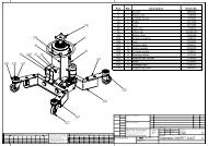
CHAPTER 8 - ACCESSORIESCAP. 8 - ACCESSORIAnextremely useful optional is the frame to set, it features agalvanized sheet iron for the overall lenght of the lift. It is usedfor making easier the installation in case of a inground lift andas side protection, other available optionals are:Set of extension hoses ( 2 metres). - Rubber support ( standardequipements for ET model ). - Rubber pads TP4B H40mm. - Crosspiece for special vehicles equipped with rubberpads. - Standard colours are: RAL 5002- RAL <strong>30</strong>02. - Ifrequested, it’s possible to have special col ours and cold galvanizing.CHAPTER 9 - SPARE PARTSUn accessorio estremamente utile è il telaio per incasso, il setè costituito da lamiera zincata che, quando montato si sviluppaper tutto il perimetro del sollevatore. Serve per facilitarnesia il posizionamento che all’eliminazione di piccoli dislivellidel suolo nel caso i modelli siano richiesti ad incasso.Altri accessori disponibili sono: Set prolunghe tubi (2 mt.). -Supporti in gomma (standard su modelli ET). - Tamponi ingomma TP4B H40 mm. per autovetture basse. - Traverse perveicoli speciali completi di supporti in gomma. - I colori standardsono: RAL 5002-RAL <strong>30</strong>02. A richiesta si possono averecolori speciali e zincatura a freddo.CAP. 9 - PARTI DI RICAMBIOSpare parts replacement and repair works should be performedin compliance with all safety rules indicated in chapter s 3 and 6.Spare parts ordering procedure.When ordering spare parts the following must be clearly specified:• Car lift serial number and year of manufacturing .• Code of the part requested (Refer to the codes in the table).• Quantity needed.• Request must be directly to the manufacturer.Request the colour of the lift, (r-red; b-blue; rp-special colour)PICT. 22 BASELa sostituzione delle parti di ricambio e gli interventi di riparazionerichiedono il rispetto di tutte le precauzioni di sicurezzaindicate ne capitolo “3” e nel cap.”6”. Procedura per l’ordinazionedelle parti di ricambio:Per ordinare le parti di ricambio necessarie occorre:• Indicare il numero di matricola del sollevatore e l’anno dicostruzione.• Indicare il codice del pezzo richiesto (vedere nella tabella lacolonna codice).• Indicare la quantità richiesta.• Indicare il colore richiesto, (R-ROSSO, B-BLU, RP-RAL PARTI-COLARE).La richiesta deve essere fatta direttamente alla casa costruttrice.FIG. 22 BASE23232232213322331434pict. - fig. 22MODELS QUANTITYPos. Code Description G<strong>25</strong>EP G<strong>30</strong>EP G<strong>35</strong>EP G<strong>25</strong>ET G<strong>30</strong>ET G<strong>35</strong>ETQ.TÀ PER MODELLIPos. Codice Descrrizione G<strong>25</strong>EP G<strong>30</strong>EP G<strong>35</strong>EP G<strong>25</strong>ET G<strong>30</strong>ET G<strong>35</strong>ET111223401G-1100R RED <strong>GEMINI</strong> BASE01G-1100B BLUE <strong>GEMINI</strong> BASE01G-1100RP RAL <strong>GEMINI</strong> BASE03-<strong>35</strong>01 HEX. SCREW14X6003-<strong>35</strong>00 HEX. SCREW14X9003-<strong>30</strong>20 14M NUT03-<strong>30</strong>34 <strong>30</strong>X34X<strong>30</strong> SELF-LUBRRICATING BUSHING222---42228-84222-8842222-242228-84222-8124111223401G-1100R BASE <strong>GEMINI</strong> ROSSA01G-1100B BASE <strong>GEMINI</strong> BLU01G-1100RP BASE <strong>GEMINI</strong> RAL PARTICOLARE03-<strong>35</strong>01 VITE TE M14X6003-<strong>35</strong>00 VITE TE M14X9003-<strong>30</strong>20 DADO M1403-<strong>30</strong>34 BOCCOLA AUTOLUBRIFICANTE <strong>30</strong>X34X<strong>30</strong>222---42228-84222-8842222-242228-84222-812427
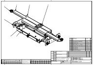
PICT. 23 BOOMSFIG. 23 BRACCI8912 122131012812 1515 13121411 129134 312 12 8121512158131214131311 12121212 11 431213101310121211 12131213131412101213131210101310121211 12131312131112101489 981141212 111513151214892131214121 12 11812 131213141515pict. - fig. 23MODELS QUANTITYPos. Code Description G<strong>25</strong>EP G<strong>30</strong>EP G<strong>35</strong>EP G<strong>25</strong>ET G<strong>30</strong>ET G<strong>35</strong>ET111111222222333<strong>30</strong>1G1109R RED LOWER INSIDE BOOM01G1109B BLUE LOWER INSIDE BOOM01G1109RP RAL LOWER INSIDE BOOM01G<strong>35</strong>11R RED LOWER INSIDE BOOM01G<strong>35</strong>11B BLUE LOWER INSIDE BOOM01G<strong>35</strong>11RP RAL LOWER INSIDE BOOM01G1110R RED LOWER OUTSIDE BOOM01G1110B BLUE LOWER OUTSIDE BOOM01G1110RP RAL LOWER OUTSIDE BOOM01G<strong>35</strong>15R RED LOWER OUTSIDE BOOM01G<strong>35</strong>15B BLUE LOWER OUTSIDE BOOM01G<strong>35</strong>15RP RAL LOWER OUTSIDE BOOM01G1112R RED UPPER OUTSIDE BOOM01G1112B BLUE UPPER OUTSIDE BOOM01G1112RP RAL UPPER OUTSIDE BOOM01G<strong>25</strong>47R LEFT RED UPPER OUTSIDE BOOM222---222------2222---222---222----222---222----222---222------2222---222---222----222---222----Q.TÀ PER MODELLIPos. Codice Descrrizione G<strong>25</strong>EP G<strong>30</strong>EP G<strong>35</strong>EP G<strong>25</strong>ET G<strong>30</strong>ET G<strong>35</strong>ET111111222222333<strong>30</strong>1G1109R BRACCIO INTERNO INFERRIORE ROSSO01G1109B BRACCIO INTERNO INFERRIORE BLU01G1109RP BRACCIO INTERNO INFERRIORE RAL PARTICOLARE01G<strong>35</strong>11R BRACCIO INTERNO INFERRIORE ROSSO01G<strong>35</strong>11B BRACCIO INTERNO INFERRIORE BLU01G<strong>35</strong>11RP BRACCIO INTERNO INFERRIORE RAL PARTICOLARE01G1110R BRACCIO ESTERNO INFERIORE ROSSO01G1110B BRACCIO ESTERNO INFERIORE BLU01G1110RP BRACCIO ESTERNO INFERIORE RAL PARTICOLARE01G<strong>35</strong>15R BRACCIO ESTERNO INFERIORE ROSSO01G<strong>35</strong>15B BRACCIO ESTERNO INFERIORE BLU01G<strong>35</strong>15RP BRACCIO ESTERNO INFERIORE RAL PARTICOLARE01G1112R BRACCIO ESTERNO SUPERIORE ROSSO01G1112B BRACCIO ESTERNO SUPERIORE BLU01G1112RP BRACCIO ESTERNO SUPERIORE RAL PARTICOLARE01G<strong>25</strong>47R BRACCIO ESTERNO SUPERIORE SX ROSSO222---222------2222---222---222----222---222----222---222------2222---222---222----222---222----28
MODELS QUANTITYPos. Code Description G<strong>25</strong>EP G<strong>30</strong>EP G<strong>35</strong>EP G<strong>25</strong>ET G<strong>30</strong>ET G<strong>35</strong>ETQ.TÀ PER MODELLIPos. Codice Descrrizione G<strong>25</strong>EP G<strong>30</strong>EP G<strong>35</strong>EP G<strong>25</strong>ET G<strong>30</strong>ET G<strong>35</strong>ET333333334444444448910111213141501G<strong>25</strong>47B LEFT BLUE UPPER OUTSIDE BOOM01G<strong>25</strong>47RP LEFT RAL UPPER OUTSIDE BOOM01G<strong>25</strong>55R RIGHT RED UPPER OUTSIDE BOOM01G<strong>25</strong>55B RIGHT BLUE UPPER OUTSIDE BOOM01G<strong>25</strong>55RP RIGHT RAL UPPER OUTSIDE BOOM01G<strong>35</strong>17R RED UPPER OUTSIDE BOOM01G<strong>35</strong>17B BLUE UPPER OUTSIDE BOOM01G<strong>35</strong>17RP RAL UPPER OUTSIDE BOOM01G<strong>25</strong>45R RED UPPER INSIDE BOOM01G<strong>25</strong>45B BLUE UPPER INSIDE BOOM01G<strong>25</strong>45RP RAL UPPER IINSIDE BOOM01G1111R RED UPPER INSIDE BOOM01G1111B BLUE UPPER INSIDE BOOM01G1111RP RAL UPPER IINSIDE BOOM01G<strong>35</strong>13R RED UPPER INSIDE BOOM01G<strong>35</strong>13B BLUE UPPER INSIDE BOOM01G<strong>35</strong>13RP RAL UPPER IINSIDE BOOM02G<strong>30</strong>04 BOOM-TO-BASE/PLATFORM FIXING PIN03-<strong>30</strong>22 SEEGER E<strong>30</strong>02G<strong>30</strong>03 BOOM COUPLING PIN02G<strong>30</strong>02 BOOM LINKAGE PIN03-<strong>30</strong>20 SELF-LUBTICATING BUSHING <strong>30</strong>/34/<strong>30</strong>03-<strong>30</strong>20 SELF-LOCKING NUT M <strong>25</strong>x1,502G<strong>30</strong>05 ROLLER FASTENING PIN02G<strong>30</strong>06 <strong>GEMINI</strong> ROLLER22222---222------8888322488-----------222---8888322488-----222---222888832248822222---222------8888322488-----------222---8888322488-----222---2228888322488333333334444444448910111213141501G<strong>25</strong>47B BRACCIO ESTERNO SUPERIORE SX BLU01G<strong>25</strong>47RP BRACCIO ESTERNO SUPERIORE RAL SX PARTICOLARE01G<strong>25</strong>55R BRACCIO ESTERNO SUPERIORE DX ROSSO01G<strong>25</strong>55B BRACCIO ESTERNO SUPERIORE DX BLU01G<strong>25</strong>55RP BRACCIO ESTERNO SUPERIORE RAL DX PARTICOLARE01G<strong>35</strong>17R BRACCIO ESTERNO SUPERIORE ROSSO01G<strong>35</strong>17B BRACCIO ESTERNO SUPERIORE BLU01G<strong>35</strong>17RP BRACCIO ESTERNO SUPERIORE RAL PARTICOLARE01G<strong>25</strong>45R BRACCIO INTERNO SUPERIORE ROSSO01G<strong>25</strong>45B BRACCIO INTERNO SUPERIORE BLU01G<strong>25</strong>45RP BRACCIO INTERNO SUPERIORE RAL PARTICOLARE01G1111R BRACCIO INTERNO SUPERIORE ROSSO01G1111B BRACCIO INTERNO SUPERIORE BLU01G1111RP BRACCIO INTERNO SUPERIORE RAL PARTICOLARE01G<strong>35</strong>13R BRACCIO INTERNO SUPERIORE ROSSO01G<strong>35</strong>13B BRACCIO INTERNO SUPERIORE BLU01G<strong>35</strong>13RP BRACCIO INTERNO SUPERIORE RAL PARTICOLARE02G<strong>30</strong>04 PERNO FISAGGIO BRACCI A BASE/PEDANA03-<strong>30</strong>22 SEEGER E<strong>30</strong>02G<strong>30</strong>03 PERNO ACCOPPIAMENTO BRACCI02G<strong>30</strong>02 PERNO ARTICOLAZIONE CENTRALE BRACCI03-<strong>30</strong>34 BOCCOLA AUTOLUBRIFICANTE <strong>30</strong>/34/<strong>30</strong>03-<strong>30</strong>20 GHIERA AUTOBLOCCANTE M <strong>25</strong>x1,502G<strong>30</strong>05 PERNO FISSAGGIO RULLO02G<strong>30</strong>06 RULLO <strong>GEMINI</strong>22222---222------8888322488-----------222---8888322488-----222---222888832248822222---222------8888322488-----------222---8888322488-----222---222888832248829
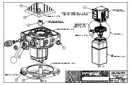
PICT. 24 MECHANICAL SAFETY DEVICES - PISTONSFIG. 24 SICUREZZE MECCANICHE - PISTONI2021232323112 <strong>35</strong> 6720202321239411381032941112 <strong>35</strong> 678102020 231914171520 231218142221 232022161421 2320pict. - fig. 24MODELS QUANTITYPos. Code Description G<strong>25</strong>EP G<strong>30</strong>EP G<strong>35</strong>EP G<strong>25</strong>ET G<strong>30</strong>ET G<strong>35</strong>ET123456789101112131415161718192021222<strong>30</strong>2G0222 COMPLETE MECHANICAL SAFETY PIN03-<strong>30</strong>13 MEDIUM GALVANIZED 6M NUT03-<strong>35</strong>06 6 FLAT WASHER05-5500 PIVOT JOINT 90° M 5 X HOSE 6X403-<strong>30</strong>14 10M SELF-LOCKING NUT05-5006 TDUOP AIR GASKET02G1022 45x17 WASHER02G-2001 AIR PISTON STEM02G2000 PISTON CYLINDER 50X5X5503-<strong>30</strong>19 M 6 x 16 TSPEI SCREW01G1020N MECHANICAL DAFETY HOOK01G1018N P1 MECHANICAL SAFETY01G1019N P2 MECHANICAL SAFETY01G1021 <strong>GEMINI</strong> PISTON HOLDER03-<strong>30</strong>55 HEX. SCREW 10 x 1604G4000 P1 PISTON04G4001 P2 PISTON04G4202 P1 PISTON GASKET KIT04G4203 P2 PISTON GASKET KIT03-<strong>30</strong>23 SHAFT SEEGER <strong>35</strong>02G<strong>30</strong>01 PISTON FASTENING PIN04-4548 PARACHUTE VALVE 3/803-<strong>30</strong>74 <strong>30</strong>X34X15 SELF-LUBRICATING BUSHING244222222421124111184282442222224211241111842824422222242112411118428244222222421124111184282442222224211241111842824422222242112411118428Q.TÀ PER MODELLIPos. Codice Descrrizione G<strong>25</strong>EP G<strong>30</strong>EP G<strong>35</strong>EP G<strong>25</strong>ET G<strong>30</strong>ET G<strong>35</strong>ET123456789101112131415161718192021222<strong>30</strong>2G0222 PISTONCINO SIC. MECC. COMPLETO03-<strong>30</strong>13 DADO M6 MEDIO ZINCATO03-<strong>35</strong>06 RONDELLA PIANA DA 605-5500 RACCORDO GIREVOLE 90° M 5 X TUBO 6X403-<strong>30</strong>14 DADO M10 AUTOBLOCCANTE05-5006 GUARNIZIONE ARIA TDUOP02G1022 RONDELLA 45x1702G-2001 STELO PER PISTONCINO ARIA02G2000 CILINDRO PER PISTONCINO 50X5X5503-<strong>30</strong>19 VITE M 6 x 16 TSPEI01G1020N AGGANCIO SICUREZZA MECCANICA01G1018N SICUREZZA MECCANICA P101G1019N SICUREZZA MECCANICA P201G1021 STAFFA REGGIPISTONE <strong>GEMINI</strong>03-<strong>30</strong>55 VITE M 10 x 16 TE04G4000 PISTONE P104G4001 PISTONE P204G4202 KIT GUARNIZIONI PISTONE P104G4203 KIT GUARNIZIONI PISTONE P203-<strong>30</strong>23 SEEGER DA <strong>35</strong> PER ALBERI02G<strong>30</strong>01 PERNO FISSAGGIO PISTONI04-4548 VALVOLA PARACADUTE FILO 3/803-<strong>30</strong>74 BOCCOLA AUTOLUBRIFICANTE <strong>30</strong>X34X15244222222421124111184282442222224211241111842824422222242112411118428244222222421124111184282442222224211241111842824422222242112411118428<strong>30</strong>
PICT. <strong>25</strong> PLATFORMFIG. <strong>25</strong> PEDANA1865151312137111pict. - fig. <strong>25</strong>MODELS QUANTITYPos. Code Description G<strong>25</strong>EP G<strong>30</strong>EP G<strong>35</strong>EP G<strong>25</strong>ET G<strong>30</strong>ET G<strong>35</strong>ETQ.TÀ PER MODELLIPos. Codice Descrrizione G<strong>25</strong>EP G<strong>30</strong>EP G<strong>35</strong>EP G<strong>25</strong>ET G<strong>30</strong>ET G<strong>35</strong>ET11111155555566666677777788888811111112131501G<strong>25</strong>37RS ANTISKID RED <strong>GEMINI</strong> <strong>25</strong> PLATFORM01G<strong>25</strong>37BS ANTISKID BLUE <strong>GEMINI</strong> <strong>25</strong> PLATFORM01G<strong>25</strong>37RPS ANTISKID RAL <strong>GEMINI</strong> <strong>25</strong> PLATFORM02G<strong>25</strong>02RS ANTISKID RED <strong>GEMINI</strong> <strong>30</strong>/<strong>35</strong> PLATFORM02G<strong>25</strong>02BS ANTISKID BLUE <strong>GEMINI</strong> <strong>30</strong>/<strong>35</strong> PLATFORM02G<strong>25</strong>02RPS ANTISKID RAL <strong>GEMINI</strong> <strong>30</strong>/<strong>35</strong> PLATFORM01G1616RS ANTISKID RED G<strong>25</strong> ON FLOOR RIGHT EXTENSION01G1616BS ANTISKID BLUE G<strong>25</strong> ON FLOOR RIGHT EXTENSION01G1616RPS ANTISKID RAL G<strong>25</strong> ON FLOOR RIGHT EXTESION01G1641RS ANTISKID RED G<strong>30</strong>/<strong>35</strong> ON FLOOR RIGHT EXTENSION01G1641BS ANTISKID BLUE G<strong>30</strong>/<strong>35</strong> ON FLOOR RIGHT EXTENSION01G1641RPS ANTISKID RAL G<strong>30</strong>/<strong>35</strong> ON FLOOR RIGHT EXTENSION01G1617RS ANTISKID RED G<strong>25</strong> ON FLOOR LEFT EXTENSION01G1617BS ANTISKID BLUE G<strong>25</strong> ON FLOOR LEFT EXTENSION01G1617RPS ANTISKID RAL G<strong>25</strong> ON FLOOR LEFT EXTESION01G1644RS ANTISKID RED G<strong>30</strong>/<strong>35</strong> ON FLOOR LEFT EXTENSION01G1644BS ANTISKID BLUE G<strong>30</strong>/<strong>35</strong> ON FLOOR LEFT EXTENSION01G1644RPS ANTISKID RAL G<strong>30</strong>/<strong>35</strong> ON FLOOR LEFT EXTENSION01G1653RS ANTISKID RED G<strong>25</strong> RIGHT EXTENSION01G1653BS ANTISKID BLUE G<strong>25</strong> RIGHT EXTENSION01G1653RPS ANTISKID G<strong>25</strong> RAL RIGHT EXTENSION01G1615RS ANTISKID RED G<strong>30</strong>/<strong>35</strong> LEFT EXTENSION01G1615BS ANTISKID BLUE G<strong>30</strong>/<strong>35</strong> LEFT EXTENSION01G1615RPS ANTISKID G<strong>30</strong>/<strong>35</strong> RAL LEFT EXTENSION01G1654RS ANTISKID RED G<strong>25</strong> LEFT EXTENSION01G1654BS ANTISKID BLUE G<strong>25</strong> LEFT EXTENSION01G1654RPS ANTISKID G<strong>25</strong> RAL LEFT EXTENSION01G1648RS ANTISKID RED G<strong>30</strong>/<strong>35</strong> RIGHT EXTENSION01G1648BS ANTISKID BLUE G<strong>30</strong>/<strong>35</strong> RIGHT EXTENSION01G1648RPS ANTISKID G<strong>30</strong>/<strong>35</strong> RAL RIGHT EXTENSION01G4006N G<strong>25</strong> FRONT SPACE COVER01G4021N G<strong>30</strong> FRONT SPACE COVER01G4022N G<strong>35</strong> FRONT SPACE COVER01G0509N G<strong>35</strong> BACK SPACE COVER02G2220 ET EXTENSION PIN02G2223 EP EXTENSION PIN222---222---222--------------------2---222---222---222-----------------2---222---222---222-----------------2222---------------222---222---2--22----222---------------222---222-2--2----222---------------222---222--2-2-11111155555566666677777788888811111112131501G<strong>25</strong>37RS PEDANA <strong>GEMINI</strong> <strong>25</strong> ROSSO ANTI SKID01G<strong>25</strong>37BS PEDANA <strong>GEMINI</strong> <strong>25</strong> BLU ANTI SKID01G<strong>25</strong>37RPS PEDANA <strong>GEMINI</strong> <strong>25</strong> RAL PARTICOLARE ANTI SKID02G<strong>25</strong>02RS PEDANA <strong>GEMINI</strong> <strong>30</strong>/<strong>35</strong> ROSSO ANTI SKID02G<strong>25</strong>02BS PEDANA <strong>GEMINI</strong> <strong>30</strong>/<strong>35</strong> BLU ANTI SKID02G<strong>25</strong>02RPS PEDANA <strong>GEMINI</strong> <strong>30</strong>/<strong>35</strong> RAL PARTICOLARE ANTI SKID01G1616RS ESTENSIONE DX A ZERO G <strong>25</strong> ROSSO ANTI SKID01G1616BS ESTENSIONE DX A ZERO G <strong>25</strong> BLU ANTI SKID01G1616RPS ESTENSIONE DX A ZERO G <strong>25</strong> RAL PARTICOLARE ANTI SKID01G1641RS ESTENSIONE DX A ZERO G <strong>30</strong>/<strong>35</strong> ROSSO ANTI SKID01G1641BS ESTENSIONE DX A ZERO G <strong>30</strong>/<strong>35</strong> BLU ANTI SKID01G1641RPS ESTENSIONE DX A ZERO G <strong>30</strong>/<strong>35</strong> RAL PARTICOLARE ANTI SKID01G1617RS ESTENSIONE SX A ZERO G <strong>25</strong> ROSSO ANTI SKID01G1617BS ESTENSIONE SX A ZERO G <strong>25</strong> BLU ANTI SKID01G1617RPS ESTENSIONE SX A ZERO G <strong>25</strong> RAL PARTICOLARE ANTI SKID01G1644RS ESTENSIONE SX A ZERO G <strong>30</strong>/<strong>35</strong> ROSSO ANTI SKID01G1644BS ESTENSIONE SX A ZERO G <strong>30</strong>/<strong>35</strong> BLU ANTI SKID01G1644RPS ESTENSIONE SX A ZERO G <strong>30</strong>/<strong>35</strong> RAL PARTICOLARE ANTI SKID01G1653RS ESTENSIONE DX G <strong>25</strong> ROSSO ANTI SKID01G1653BS ESTENSIONE DX G <strong>25</strong> BLU ANTI SKID01G1653RPS ESTENSIONE DX G <strong>25</strong> RAL PARTICOLARE ANTI SKID01G1615RS ESTENSIONE SX G <strong>30</strong>/<strong>35</strong> ROSSO ANTI SKID01G1615BS ESTENSIONE SX G <strong>30</strong>/<strong>35</strong> BLU ANTI SKID01G1615RPS ESTENSIONE SX G <strong>30</strong>/<strong>35</strong> RAL PARTICOLARE ANTI SKID01G1654RS ESTENSIONE SX G <strong>25</strong> ROSSO ANTI SKID01G1654BS ESTENSIONE SX G <strong>25</strong> BLU ANTI SKID01G1654RPS ESTENSIONE SX G <strong>25</strong> RAL PARTICOLARE ANTI SKID01G1648RS ESTENSIONE DX G <strong>30</strong>/<strong>35</strong> ROSSO ANTI SKID01G1648BS ESTENSIONE DX G <strong>30</strong>/<strong>35</strong> BLU ANTI SKID01G1648RPS ESTENSIONE DX G <strong>30</strong>/<strong>35</strong> RAL PARTICOLARE ANTI SKID01G4006N COPRI SPAZIO ANTERIORE G <strong>25</strong>01G4021N COPRI SPAZIO ANTERIORE G <strong>30</strong>01G4022N COPRI SPAZIO ANTERIORE G <strong>35</strong>01G0509N COPRI SPAZIO POSTERIORE G <strong>35</strong>02G2220 PERNO PER ESTENSIONE ET02G2223 PERNO PER ESTENSIONE EP222---222---222--------------------2---222---222---222-----------------2---222---222---222-----------------2222---------------222---222---2--22----222---------------222---222-2--2----222---------------222---222--2-2-31
PICT. 26 CONTROL BOXFIG. 26 CENTRALINA191831421841128131171344123840 37 <strong>35</strong> 3936913111772310<strong>35</strong>26322029282421<strong>25</strong>1233347888<strong>30</strong>1631 12MODELS QUANTITYPos. Code Description G<strong>25</strong>EP G<strong>30</strong>EP G<strong>35</strong>EP G<strong>25</strong>ET G<strong>30</strong>ET G<strong>35</strong>ET06-6012 MAIN SWITCH FINISHING06-6055 LE2 4X16 A MAIN SWITCH01-1618R RED CABINET01-1618B BLUE CABINET01-1618RP RAL CABINET06-0997 <strong>GEMINI</strong> TOUCHPAD05-5000 AIR ELECTROVALVE01-1622R RED DOOR01-1622B RED/BLUE DOOR01-1622RP RAL DOOR111111111111111111111111111111111111111111111111111111111111123334788806-6012 FINITURE PER INTERRUTTORE GENERALE06-6055 INTERRUTTORE GENERALE LE2 4X16 A01-1618R ARMADIETTO ROSSO01-1618B ARMADIETTO BLU01-1618RP ARMADIETTO RAL PARTICOLARE06-0997 TASTIERA <strong>GEMINI</strong>05-5000 ELETTROVALVOLA ARIA01-1622R SPORTELLO ROSSO01-1622B SPORTELLO ROSSO BLU01-1622RP SPORTELLO RAL PARTICOLARE22 pict. - fig. 26Q.TÀ PER MODELLIPos. Codice Descrrizione G<strong>25</strong>EP G<strong>30</strong>EP G<strong>35</strong>EP G<strong>25</strong>ET G<strong>30</strong>ET G<strong>35</strong>ET11111111111111111111111111111111111111111111111111111111111132
MODELS QUANTITYPos. Code Description G<strong>25</strong>EP G<strong>30</strong>EP G<strong>35</strong>EP G<strong>25</strong>ET G<strong>30</strong>ET G<strong>35</strong>ETQ.TÀ PER MODELLIPos. Codice Descrrizione G<strong>25</strong>EP G<strong>30</strong>EP G<strong>35</strong>EP G<strong>25</strong>ET G<strong>30</strong>ET G<strong>35</strong>ET9101112131416171818181919192021222324<strong>25</strong>26272829<strong>30</strong>31323334<strong>35</strong>36373839404106-612604-458<strong>30</strong>4-402401-1610N04G460006-03<strong>35</strong>05-404001-161101-1624R01-1624B01-1624RP01-16<strong>25</strong>R01-16<strong>25</strong>B01-16<strong>25</strong>RP05-550204-458604-458402-220004-458504-410403-<strong>30</strong>8603-<strong>30</strong>8403-<strong>30</strong>8503-<strong>30</strong>8003-312<strong>30</strong>3-345603-<strong>30</strong>8504-459806-601006-61<strong>25</strong>06-652406-615106-612706-612<strong>30</strong>6-615006-65243 KW, 4 POLES , 220-380 THREE-PHASEMOTOR 5 L. AP 100 PUMPTANK VENT KNOBOIL TANKHYDRAULIC BLOCKG 97/GLP SMELECTRIC CARD GE-GLP 97 SMAIR FILTERTANK COVER MOD 97RED CONSOLLEBLUE CONSOLLERAL CONSOLLERED CONSOLLE COVERBLUE CONSOLLE COVERRAL CONSOLLE COVERWHITE RILSAN AIR TUBE 6X4PVC 3/8 L 270 TUBEFLEX TUBER2TFG3/8MOTOR FLANGEPVC L170 3/8 TUBEOIL INTAKE FILTERM8x<strong>30</strong> TCEI GALVANIZED SCREWM6X<strong>25</strong> TCEI GALVANIZED SCREWM8X16 TCEI GALVANIZED SCREWM8X12 TCEI SCREWM8X16 TE GALVANIZED SCREW8X16 FLAT WASHERM8X16 TCEI GALVANIZED SCREWCOUPLING JOINT50VA 220-380-0-24 MONOPHASE TRANSFORMER4KW 24VCC CONTACTOR5X20 1A FUSECBD 6 TERMINALDIN GUIDEDIN GUIDE 3X32A FUSE HOLDERTE6 GROUND TERMINAL5X20 1A GLASS FUSE1111111111111111111144442231111311111111111111111111111144442231111311111111111111111111111144442231111311111111111111111111111144442231111311111111111111111111111144442231111311111111111111111111111144442231111311119101112131416171818181919192021222324<strong>25</strong>26272829<strong>30</strong>31323334<strong>35</strong>36373839404106-612604-458<strong>30</strong>4-402401-1610N04G460006-03<strong>35</strong>05-404001-161101-1624R01-1624B01-1624RP01-16<strong>25</strong>R01-16<strong>25</strong>B01-16<strong>25</strong>RP05-550204-458604-458402-220004-458504-410403-<strong>30</strong>8603-<strong>30</strong>8403-<strong>30</strong>8503-<strong>30</strong>8003-312<strong>30</strong>3-345603-<strong>30</strong>8504-459806-618106-61<strong>25</strong>06-653706-615106-612706-612<strong>30</strong>6-615006-6524MOTORE TRIFASE 3 KW, 4 POLI, 220-380POMPA 5 L. AP 100TAPPO SERBATOIO CON SFIATOSERBATOIO OLIOBLOCCO IDRAULICO G 97/GLP SMSCHEDA ELETTRICA GE-GLP 97 SMGRUPPO LUB. REG. FILTRO ARIACOPERCHIO SERBATOIO MOD 97CONSOLLE ROSSACONSOLLE BLUCONSOLLE RAL PARTICOLARECOPERCHIO CONSOLLE ROSSOCOPERCHIO CONSOLLE BLUCOPERCHIO CONSOLLE RAL PARTICOLARETUBO RILSAN ARIA 6X4 BIANCOTUBO PVC 3/8 L 270TUBO FLEX R2TFG3/8FLANGIA MOTORETUBO PVC L170 3/8FILTRO DI ASPIRAZIONE OLIOVITE M8x<strong>30</strong> TCEI ZINCATAVITE M6X<strong>25</strong> TCEI ZINCATAVITE M8X16 TCEI ZINCATAVITE M8X12 TCEIVITE M8X16 TE ZINCATARONDELLA PIANA 8X16VITE M8X16 TCEI ZINCATAGIUNTO DI ACCOPPIAMENTOTRASFORMATORE 70VA 220-380 V 24 VCONTATTORE 4KW 24VCCFUSIBILE 10X<strong>30</strong> 20AMORSETTO PASSANTE CBD 6GUIDA DINPORTAFUSIBILE 3X32A DA GUIDA DINMORSETTO DI TERRA TE6FUSIBILE DI VETRO 5X20 1A11111111111111111111444422311133111111111111111111111111444422311133111111111111111111111111444422311133111111111111111111111111444422311133111111111111111111111111444422311133111111111111111111111111444422311133111133
PICT. 27 ELECTRIC SAFETY DEVICESFIG. 27 SICUREZZE ELETTRICHE5 3114146pict. - fig. 27MODELS QUANTITYPos. Code Description G<strong>25</strong>EP G<strong>30</strong>EP G<strong>35</strong>EP G<strong>25</strong>ET G<strong>30</strong>ET G<strong>35</strong>ET1345606-0<strong>30</strong>202G<strong>30</strong>0701-162006-660606-6603D12 PNP 10-<strong>30</strong> V.DC 8 METERS PROXIMETRYGE PROXIMITY CONTACT CAMG97 AUTOLEVELLING PROXIMETRY BRACKET8 METERS CABLE PHOTOCELLD 80 ONE-HOLE REFRACTOR422114221142211422114221142211Q.TÀ PER MODELLIPos. Codice Descrrizione G<strong>25</strong>EP G<strong>30</strong>EP G<strong>35</strong>EP G<strong>25</strong>ET G<strong>30</strong>ET G<strong>35</strong>ET1345606-0<strong>30</strong>202G<strong>30</strong>0701-162006-660606-6603PROXIMETRI D12 PNP 10-<strong>30</strong> V.DC 8 METRICAMME CONTATTO PROXIMITY GESTAFFA PROXIMETRI AUTOL. G97FOTOCELLULA CAVO 8 METRICATARIFRANGENTE D 80 UN FORO422114221142211422114221142211PICT. 28 PNEUMATIC AND HYDRAULIC ALIMENTATIONSFIG. 28 ALIMENTAZIONI IDRAULICHE E PNEUMATICHE4275613289pict. - fig. 28MODELS QUANTITYPos. Code Description G<strong>25</strong>EP G<strong>30</strong>EP G<strong>35</strong>EP G<strong>25</strong>ET G<strong>30</strong>ET G<strong>35</strong>ET12345678904-456404-456004-456204-456<strong>30</strong>4-455905-550404-456104-401105-5016CONNECTED “F” PIPE R2 1/4CONNECTED “B” PIPE R1CONNECTED “E” PIPE R2CONNECTED “D”PIPE R2 1/4CONNECTED “A” PIPE R26X4 POLYETHYLENE AIR PIPECONNECTED “C” PIPE R2“T” CONNECTION 3/86X4 PIPE “T” RAPID AIR CONNECTION11111111111111111111111111111114m. 14m. 14m. 14m. 14m. 14m.111111111111111111Q.TÀ PER MODELLIPos. Codice Descrrizione G<strong>25</strong>EP G<strong>30</strong>EP G<strong>35</strong>EP G<strong>25</strong>ET G<strong>30</strong>ET G<strong>35</strong>ET12345678904-456404-456004-456204-456<strong>30</strong>4-455905-500404-456104-401105-5016TUBO “F” R2 1/4 RACCORDATOTUBO “B” R1 RACCORDATOTUBO “E” R2 RACCORDATOTUBO “D” R2 1/4 RACCORDATOTUBO “A” R2 RACCORDATO111111111111111111111111111111TUBO ARIA POLIETILENE 6X414m. 14m. 14m. 14m. 14m. 14m.TUBOC” R2 RACCORDATORACCORDO A “T” 3/8RACCORDO A “T” ARIA SUPER RAPIDO X TUBO 6X411111111111111111134
MAINTENANCE BOOKINITIAL TESTN. DESCRIPTION TESTYES NO NotesLIBRETTO METROLOGICOVERIFICA INIZIALEN. DESCRIZIONE VERIFICASI NO Note1Floor consistency check1Controllo consistenza pavimento.2Safety distances check (from walls, columns,ceiling, other machines etc.)2Controllo distanze di sicurezza da muri,colonne, soffitto, altre macchine ecc.3Power supply line check.3Controllo linea alimentazione elettrica.4Pneumatic supply line check.4Controllo linea alimentazione pneumatica.5Lift levelling check.5Controllo livellamento ponte.6Lift working check.6Controllo funzionalità sollevatore.7Mechanical safeties working check.7Controllo funzionalità sicurezze meccaniche.8Electric safeties working check.8Controllo funzionalità sicurezze elettriche.9Loaded lift check.9Controllo sollevatore con carico.10Lift fixing check.10Controllo fissaggio sollevatore.11Oil level check.11Controllo livello olio.1213Hydraulic failure check.Pneumatic failure check.1213Controllo perdite eventuali circuito idraulicoControllo perdite eventuali circuito pneumatico14Operating instruction14Istruzioni all’usoNOTES:NOTE:InstallerL’installatoreStamp and signatureTimbro e firmaInstallerL’installatoreStamp and signatureTimbro e firmaDateNext test on:DataProssima verifica<strong>35</strong>
PERIODICAL OR OCCASIONAL VISITN. TEST DESCRIPTIONYES NO Notes123Lift maintenance and cleaning check.Mechanical safeties working check.Electric safeties working check.N. DESCRIZIONE VERIFICASI NO NoteControllo stato di mantenimento e pulizia1 sollevatore.Controllo funzionalita’ sicurezze meccaniche.23VERIFICA PERIODICA O OCCASIONALEControllo funzionalità sicurezze elettriche.4Oil level check.4Controllo livello olio.5Rollers slides greasing.5Ingrassaggio guide di scorrimento rulli.6Movable parts greasing.6Ingrassaggio organi di movimento.7High pressure flexible pipes check.7Controllo stato tubi flessibili ad alta pressione.8Hydraulic failure check.8Controllo perdite eventuali circuito idraulico.9Pneumatic failure check.9Controllo perdite circuito pneumatico10Lift levelling check.10Controllo livellamento sollevatore11Loaded lift check.11Controllo sollevatore con caricoNOTES:NOTE:Result of visitPositiveEsito visitaPositivoNegativeNegativoInstallerL’installatoreStamp and signatureTimbro e firmaInstallerL’installatoreStamp and signatureTimbro e firmaDateNext test onDataProssima verifica36
PERIODICAL OR OCCASIONAL VISITN. TEST DESCRIPTIONYES NO Notes123Lift maintenance and cleaning check.Mechanical safeties working check.Electric safeties working check.N. DESCRIZIONE VERIFICASI NO NoteControllo stato di mantenimento e pulizia1 sollevatore.Controllo funzionalita’ sicurezze meccaniche.23VERIFICA PERIODICA O OCCASIONALEControllo funzionalità sicurezze elettriche.4Oil level check.4Controllo livello olio.5Rollers slides greasing.5Ingrassaggio guide di scorrimento rulli.6Movable parts greasing.6Ingrassaggio organi di movimento.7High pressure flexible pipes check.7Controllo stato tubi flessibili ad alta pressione.8Hydraulic failure check.8Controllo perdite eventuali circuito idraulico.9Pneumatic failure check.9Controllo perdite circuito pneumatico10Lift levelling check.10Controllo livellamento sollevatore11Loaded lift check.11Controllo sollevatore con caricoNOTES:NOTE:Result of visitPositiveEsito visitaPositivoNegativeNegativoInstallerL’installatoreStamp and signatureTimbro e firmaInstallerL’installatoreStamp and signatureTimbro e firmaDateNext test onDataProssima verifica37
TESTS TO BE MADE BY THE USERTESTS DURING USEVERIFICA DA PARTE DELL’UTILIZZATORECONTROLLI DURANTE L’UTILIZZON.TEST DESCRIPTIONN.DESCRIZIONE VERIFICA1Levelling check.1Controllo livellamento2Hydraulic failure check.2Controllo eventuali perdite circuito idraulico3Pneumatic failure check.3Controllo eventuali perdite circuito pneumatico4Safety devices working check.4Controllo funzionalità sistemi di sicurezzaMONTHLY TESTSCONTROLLI MENSILIN.TEST DESCRIPTIONN.DESCRIZIONE VERIFICA1Lift through cleaning.1Pulizia generale del sollevatore2Rollers slides greasing2Ingrassaggio guide di scorrimento rulli3Cylinders air bleeding (if necessary).3Spurgo aria dai cilindri (se necessario)HALF-YEARLY TESTSCONTROLLI SEMESTRALIN.TEST DESCRIPTIONN.DESCRIZIONE VERIFICA1Oil level check.1Controllo livello olio2High pressure flexible pipes check.2Controllo stato tubi flessibili ad alta pressioneIN CASE OF ANOMALY, STOP THELIFT AND CONTACT OUR SERVICEDEPARTEMENT IMMEDIATELY.IN CASO DI COMPORTAMENTOANOMALO DEL SOLLEVATORE,FERMARLO E CONTATTARE IMME-DIATAMENTE IL NS. SERVIZIO DIASSISTENZA.38
REPAIRRIPARAZIONEFailure:Guasto segnalato:Action:Intervento:DateStamp and signatureDataTimbro e firmaREPAIRRIPARAZIONEFailure:Guasto segnalato:Action:Intervento:DateStamp and signatureDataTimbro e firma39