pic-pg3b parallel port pic microcontroller programmer - Olimex
pic-pg3b parallel port pic microcontroller programmer - Olimex pic-pg3b parallel port pic microcontroller programmer - Olimex
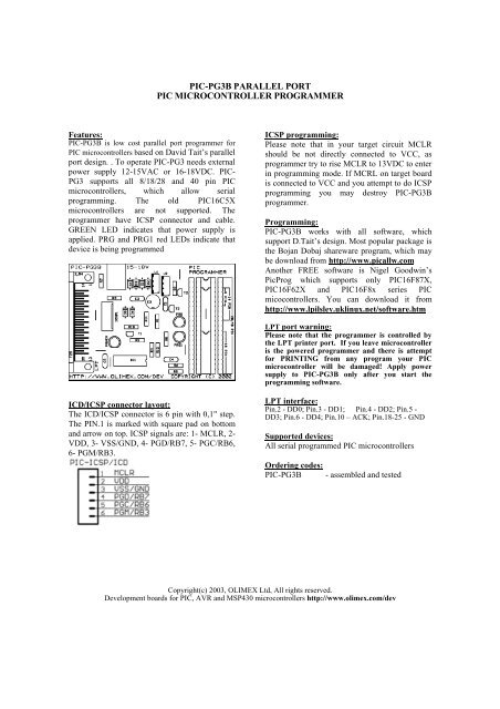
PIC-PG3B PARALLEL PORTPIC MICROCONTROLLER PROGRAMMERFeatures:PIC-PG3B is low cost parallel port programmer forPIC microcontrollers based on David Tait’s parallelport design. . To operate PIC-PG3 needs externalpower supply 12-15VAC or 16-18VDC. PIC-PG3 supports all 8/18/28 and 40 pin PICmicrocontrollers, which allow serialprogramming. The old PIC16C5Xmicrocontrollers are not supported. Theprogrammer have ICSP connector and cable.GREEN LED indicates that power supply isapplied. PRG and PRG1 red LEDs indicate thatdevice is being programmedICSP programming:Please note that in your target circuit MCLRshould be not directly connected to VCC, asprogrammer try to rise MCLR to 13VDC to enterin programming mode. If MCRL on target boardis connected to VCC and you attempt to do ICSPprogramming you may destroy PIC-PG3Bprogrammer.Programming:PIC-PG3B works with all software, whichsupport D.Tait’s design. Most popular package isthe Bojan Dobaj shareware program, which maybe download from http://www.picallw.comAnother FREE software is Nigel Goodwin’sPicProg which supports only PIC16F87X,PIC16F62X and PIC16F8x series PICmicocontrollers. You can download it fromhttp://www.lpilsley.uklinux.net/software.htmLPT port warning:Please note that the programmer is controlled bythe LPT printer port. If you leave microcontrolleris the powered programmer and there is attemptfor PRINTING from any program your PICmicrocontroller will be damaged! Apply powersupply to PIC-PG3B only after you start theprogramming software.ICD/ICSP connector layout:The ICD/ICSP connector is 6 pin with 0,1" step.The PIN.1 is marked with square pad on bottomand arrow on top. ICSP signals are: 1- MCLR, 2-VDD, 3- VSS/GND, 4- PGD/RB7, 5- PGC/RB6,6- PGM/RB3.LPT interface:Pin.2 - DD0; Pin.3 - DD1; Pin.4 - DD2; Pin.5 -DD3; Pin.6 - DD4; Pin.10 – ACK; Pin.18-25 - GNDSupported devices:All serial programmed PIC microcontrollersOrdering codes:PIC-PG3B- assembled and testedCopyright(c) 2003, OLIMEX Ltd, All rights reserved.Development boards for PIC, AVR and MSP430 microcontrollers http://www.olimex.com/dev
PIC-PG3B PARALLEL PORTPIC MICROCONTROLLER PROGRAMMERFeatures:PIC-PG3B is low cost <strong>parallel</strong> <strong>port</strong> <strong>programmer</strong> forPIC <strong>microcontroller</strong>s based on David Tait’s <strong>parallel</strong><strong>port</strong> design. . To operate PIC-PG3 needs externalpower supply 12-15VAC or 16-18VDC. PIC-PG3 sup<strong>port</strong>s all 8/18/28 and 40 pin PIC<strong>microcontroller</strong>s, which allow serialprogramming. The old PIC16C5X<strong>microcontroller</strong>s are not sup<strong>port</strong>ed. The<strong>programmer</strong> have ICSP connector and cable.GREEN LED indicates that power supply isapplied. PRG and PRG1 red LEDs indicate thatdevice is being programmedICSP programming:Please note that in your target circuit MCLRshould be not directly connected to VCC, as<strong>programmer</strong> try to rise MCLR to 13VDC to enterin programming mode. If MCRL on target boardis connected to VCC and you attempt to do ICSPprogramming you may destroy PIC-PG3B<strong>programmer</strong>.Programming:PIC-PG3B works with all software, whichsup<strong>port</strong> D.Tait’s design. Most popular package isthe Bojan Dobaj shareware program, which maybe download from http://www.<strong>pic</strong>allw.comAnother FREE software is Nigel Goodwin’sPicProg which sup<strong>port</strong>s only PIC16F87X,PIC16F62X and PIC16F8x series PICmicocontrollers. You can download it fromhttp://www.lpilsley.uklinux.net/software.htmLPT <strong>port</strong> warning:Please note that the <strong>programmer</strong> is controlled bythe LPT printer <strong>port</strong>. If you leave <strong>microcontroller</strong>is the powered <strong>programmer</strong> and there is attemptfor PRINTING from any program your PIC<strong>microcontroller</strong> will be damaged! Apply powersupply to PIC-PG3B only after you start theprogramming software.ICD/ICSP connector layout:The ICD/ICSP connector is 6 pin with 0,1" step.The PIN.1 is marked with square pad on bottomand arrow on top. ICSP signals are: 1- MCLR, 2-VDD, 3- VSS/GND, 4- PGD/RB7, 5- PGC/RB6,6- PGM/RB3.LPT interface:Pin.2 - DD0; Pin.3 - DD1; Pin.4 - DD2; Pin.5 -DD3; Pin.6 - DD4; Pin.10 – ACK; Pin.18-25 - GNDSup<strong>port</strong>ed devices:All serial programmed PIC <strong>microcontroller</strong>sOrdering codes:PIC-PG3B- assembled and testedCopyright(c) 2003, OLIMEX Ltd, All rights reserved.Development boards for PIC, AVR and MSP430 <strong>microcontroller</strong>s http://www.olimex.com/dev


