Create successful ePaper yourself
Turn your PDF publications into a flip-book with our unique Google optimized e-Paper software.
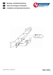
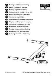
DF<strong>GB</strong>EIEinbauanleitungElektroanlage für AnhängevorrichtungInstructions de montageInstallation électrique pour dispositif d’attelageInstallation InstructionsElectrical System for Towing HitchIstruzioni di montaggioImpianto elettrico per il gancio di traino344 503 391 101 - 34/01<strong>VW</strong> <strong>Caddy</strong>, <strong>Seat</strong> <strong>Inca</strong>1
DEinbauanleitungElektroanlage für Anhängevorrichtung 7/13-polig<strong>Westfalia</strong> Nr.: 344 503 300 107/ 113Verwendungsbereich: <strong>VW</strong> <strong>Caddy</strong> ab 12/95<strong>Seat</strong> <strong>Inca</strong> ab 12/95Allgemeine Hinweise:Vor Arbeitsbeginn bitte die Einbauanleitung durchlesen.Gebohrte Löcher müssen entgratet und anschließend mit Schutzlack gestrichen werden.Die Installation des Elektrosatzes darf nur bei abgeklemmter Batterie von Fachpersonal durchgeführtwerden.Vor dem Bohren bitte prüfen, daß genügend Freiraum hinter der Verkleidung vorhanden ist.Achtung: Elektronisch gespeicherte Daten (Autoradio, Bordcomputer, etc.) können verloren gehen.Die Steckdose in diesem Kabelsatz hat serienmäßig einen Abschaltkontakt für die fahrzeugeigeneNebelschlußleuchte. Bei Anhängerbetrieb ist die Nebelschlußleuchte des Zugfahrzeugs außer Funktion.Bei Anhängern ohne Nebelschlußleuchte muß diese nachgerüstet werden.Die Kontrollleuchte blinkt nur bei angekuppelten Anhänger. Einmaliges aufblinken ohne Anhängerist zulässig.Ein Steckdosenadapter darf nur im Anhängerbetrieb genutzt werden. Nach dem Anhängerbetriebist dieser zu entfernen!Maßgebend für alle Rechtsfragen ist die deutschsprachige Ausgabe dieser Einbauanleitung.Änderungen vorbehalten!2
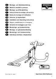
Montage des Blinkgebers und der Anhänger - KontrolleuchteD1. Minusklemme von der Batterie abklemmen.2. Verkleidung der Zentralelektrik im Fußraum der Fahrerseite entfernen.3. Vorhandenen Blinkgeber gegen den gelieferten Blinkgeber austauschen.Den 2-aderigen vorkonfektionierten Leitungsbaum in das Relais einstecken und zurKontrolleuchte verlegen.4. Kontrollampe in der Frontverkleidung an geeigneter Stelle im Sichtbereich des Fahrersanbringen. (Auf ausreichende Bohrfreiheit achten; Bohrung ø10,5 mm oder 12,0 mmje nach Ausführung der Kontrolleuchte).Die beiden Kabel auf die Flachstecker der Kontrollampe von hinten aufschieben.Verlegung des Leitungsstranges1. Verkleidungen soweit notwendig hinten seitlich lösen.Im Fahrzeugheck befinden sich links und rechts unten je ein schwarzerKunststoffstopfen zur Entwässerung.2. Die freien Leitungsenden ca. 50mm aus dem Schlauchende einrichten.3. Den 4-adrigen (6-adrigen) Leitungssatz (mit den Adern grau, blau, sw/ws und grau/sw)von innen aus durch die linke Entwässerung stecken und zum Halteblech für die Steckdoseverlegen.4. Den anderen 4-adrigen (5-adrigen) Leitungssatz von innen aus durch die rechteEntwässerung stecken und zum Halteblech für die Steckdose verlegen.5. Beide Leitungsstränge mit den mitgelieferten Kabelbindern fixieren.6. Beide Leitungsstränge durch das Loch im Halteblech stecken und die Steckdosendichtung aufziehen.7. Kontakteinsatz aus dem Steckdosengehäuse drücken und die Steckdose nach demBelegungsplan anschließen.8. Innenteil mit dem Steckdosengehäuse zusammenstecken, Steckdosendichtungplatzieren und mit den beiliegenden Schrauben auf den Halter schrauben.Auf ordnungsgemäßen Sitz der Dichtungselemente achten.3
DBelegung der 7 - poligen SteckdoseStromkreis Leitung KontaktBlinkleuchte links schwarz/weiß 1/LNebelschlußleuchte blau 2/54gNebelschlußleuchte grau 2a/8Masse schwarz 3/31Blinkleuchte, rechts schwarz/grün 4/RSchlußleuchte, rechts grau/rot 5/58RBremsleuchte schwarz/rot 6/54Schlußleuchte, links grau/schwarz 7/58LBelegung der 13 - poligen SteckdoseStromkreis Leitung KontaktBlinkleuchte links schwarz/weiß 1Nebelschlußleuchte blau 2Nebelschlußleuchte grau 2aMasse (Stromkreis 1-8) schwarz 3Blinkleuchte, rechts schwarz/grün 4Schlußleuchte, rechts grau/rot 5Bremsleuchte schwarz/rot 6Schlußleuchte, links grau/schwarz 7Rückfahrscheinwerfer weiß 8Dauerplus rot; 2,5mm² 9Ladeleitung -- 10nicht zugeteilt -- 11nicht zugeteilt -- 12Masse (Stromkreis 9-12) braun; 2,5mm² 13Ausgebaute Teile wieder einbauen, Minusklemme der Batterie wieder anschließen.Alle Funktionen mit einem geeigneten Prüfgerät (mit Belastungswiderständen) oder mit einemAnhänger prüfen!Hinweis:Die Dauerstromversorgung (großer Stecker) wird nur bei der 13-pol. Version bei Bedarfangeschlossen. In den meisten Fällen ist ein Kabelschacht im Innenraum unter demTeppichboden vorhanden. Die Leitung durch eine vorhandene Kabeldurchführung bis in denMotorraum verlegen.Änderungen vorbehalten!4
FInstructions de montageInstallation électrique pour dispositif d’attelage 7/13 bornesRéférence <strong>Westfalia</strong>: 344 503 300 107 / 113Domaine d’utilisation: <strong>VW</strong> <strong>Caddy</strong> à partir de décembre 95<strong>Seat</strong> <strong>Inca</strong> à partir de décembre 95Informations générales:Avant de commencer les travaux, veuillez lire les instructions de montage.Les trous venant d’être percés doivent être ébarbés et protégés en y passant de la laque spéciale.Seul du personnel qualifié a le droit d’installer le set électrique après avoir débranché la batterie.Veuillez contrôler avant de percer les trous s’il y a bien suffisamment d’espace derrière l’habillage.Attention : les données électroniques mémorisées (autoradio, ordinateur de bord, etc.) peuventdisparaître.La prise de courant de ce faisceau comporte, de série, un contact de coupure pour l’antibrouillardarrière de la voiture. L’antibrouillard arrière de celle-ci est neutralisé lorsqu’une remorque/caravaney est attachée.Un feu antibrouillard doit être installé sur les remorques n'en disposant pas.Le témoin de contrôle clignote uniquement si une remorque/caravane est attachée. Il n’y a pasd’anomalie s’il clignote une seule fois alors qu’une remorque/caravane n’est pas attachée.Un adaptateur pour prise de courant ne doit être utilisé que si une remorque/caravane est tractée.Le retirer après l’avoir détachée!L’édition en allemand de ces instructions de montage est la seule valable en ce qui concerne lesquestions juridiques.Tous droits de modifications réservés!5
FMontage de la centrale clignotante et de la lampe témoin de la remorque1. Déconnecter le câble de la masse de la batterie.2. Retirer l'habillage du système électrique central, dans l'espace avant, côté conducteur.3. Remplacer la centrale clignotante présente par la centrale clignotante fournie.Raccorder le faisceau à deux câbles préconfectionné au relais et le poser vers la lampetémoin.4. Positionner la lampe témoin à un endroit approprié sur l'habillage avant, dans le champ devision du conducteur.(garder une place suffisante pour le perçage ; ø10,5 mm ou 12,0 mm selon le type delampe témoin).Enfiler les deux fils par l'arrière sur la fiche mâle de la lampe témoin.Pose du faisceau1. Détacher les habillages latéraux arrière autant que nécessaire.A l'arrière du véhicule, se trouve, du côté gauche comme du côté droit, un bouchon enplastique pour l'évacuation de l'eau.2. Les extrémités des câbles doivent dépasser d'env. 50 mm hors de la gaine.3. Poser le faisceau à quatre fils (six fils) (fils gris, bleu, noir/blanc et gris/noir) depuisl'intérieur à travers l'orifice d'évacuation gauche jusqu'à la tôle de support pour la prise.4. Poser l'autre faisceau à quatre fils (cinq fils) depuis l'intérieur à travers l'orificed'évacuation droit et jusqu'à la tôle de support de la prise.5. Fixer les deux faisceaux avec les colliers joints.6. Faire passer les deux faisceaux par le trou de la tôle de support et enfiler la garnitureétanche de la prise.7. Extraire l'insert électrique du boîtier de la prise et connecter la prise selon le pland'affectation.8. Emboîter la partie interne avec le boîtier de prise, mettre la garniture étanche en place etvisser sur le support avec les vis fournies.Veiller au logement correct des éléments d'étanchéité.6
Disposition de la prise à 7 pôlesFcircuit électrique câble contactclignotant gauche noir/blanc 1/LFeu antibrouillard arrière bleu 2/54gFeu antibrouillard arrière gris 2a/8masse noir 3/31clignotant droit noir/vert 4/Rfeu arrière droit gris/rouge 5/58Rfeu stop noir/rouge 6/54feu arrière gauche gris/noir 7/58LDisposition de la prise à 13 pôlescircuit électrique câble contactclignotant gauche noir/blanc 1Feu antibrouillard arrière bleu 2Feu antibrouillard arrière gris 2amasse (circuit électrique 1-8) noir 3clignotant droit noir/vert 4feu arrière droit gris/rouge 5feu stop noir/rouge 6feu arrière gauche gris/noir 7phares de recul blanc 8borne positive constante rouge; 2,5mm² 9câble de charge -- 10sans fonction -- 11sans fonction -- 12masse (circuit électrique 9-12) marron; 2,5mm² 13Remonter les pièces démontées, connecter à nouveau la borne négative de la batterie.Vérifier toutes les fonctions avec l'appareil de contrôle approprié (avec des résistances decharge) ou avec une remorque !Note :L'alimentation permanente en courant (grande prise) n'est raccordée que dans le cas de laversion à 13 pôles, si nécessaire.Dans la plupart des cas, une conduite de câbles est prévue sous le tapis de sol. Passer lecâble dans une conduite de câbles disponible jusqu'au compartiment moteur.Tous droits de modifications réservés!7
<strong>GB</strong>Installation InstructionsElectrical System for Towing Hitch 7/13-pin<strong>Westfalia</strong> Order No.: 344 503 300 107 / 113Area of Application: <strong>VW</strong> <strong>Caddy</strong> from 12/95<strong>Seat</strong> <strong>Inca</strong> from 12/95General Information:Before starting work, please read the installation instructions.The holes drilled must be deburred and then coated with anti-corrosion paint.The electrical set may only be installed by specially-trained personnel with the battery disconnected.Please make sure before drilling that there is sufficient clearance behind the trim.Important: Any electronically stored data (car radio, onboard computer etc.) may be lost.The electrical socket in this wiring harness is provided with a switch-off contact for the vehicles ownrear fog light as standard equipment. During trailer towing the rear fog light of the pulling vehicle isinoperative.A rear fog lamp must be retrofitted for towed vehicles that do not already have one.The indicator lamp only flashes when a trailer is hitched to the vehicle. One-time flashing without atrailer is permitted.An electrical socket adapter may only be used during trailer towing, and must be removed aftertrailer towing is completed!The German version of these installation instructions shall be applicable in event of any legalquestions.Subject to modification!8
<strong>GB</strong>Installation of flasher and towed vehicle control light1. Disconnect the negative terminal from the battery.2. Remover covering of the main electrical system in the driver's leg room.3. Replace the vehicle's flasher with the supplied flasher.Plug the 2-wired ready-made cable tree into the relay and lay it out to the control light.4. Attach the control light in a suitable location in the front panelling within the driver's range ofview.(Please observe sufficient drilling leeway: bore ø10.5 mm or 12.0 mm (depending on typeof control light.)Pull the two wires onto the control light's flat plugs from behind.Laying wire lane1. Loosen coverings on the rear side as far as necessary.A black rubber plug is located in the right and left of the vehicle's rear for drainagepurposes.2. Fit the free ends approx. 50mm from the pipe ends.3. Pass the 4-wired (6-wired) line set (with the grey, blue, bw/wb and grey/bw leads) from theinside through the left drainage hole and lay it to the socket retaining plate.4. Pass the other 4-wired (5-wired) line set from the inside through the right drainage holeand lay it to the socket retaining plate.5. Fasten both wire lanes with the enclosed cable binders.6. Insert both wire lanes through the hole in the retaining plate and fit the socket seals.7. Push the contact holder away from the socket housing and connect the socket according tothe wiring plan.8. Fit together the inner part with the socket housing, put the socket sealing in place andscrew onto the holder with the enclosed screws.Make sure the seals sit properly.9
<strong>GB</strong>Allocation of the 7-pin socketCircuit Wire ContactLeft turn signal lamp black/white 1/LRear fog lamp blue 2/54gRear fog lamp grey 2a/8Earth black 3/31Right turn signal lamp black/green 4/RRight tail light gray/red 5/58RStop light black/red 6/54Left tail light gray/black 7/58LAllocation of the 13-pin socketCircuit Wire ContactLeft turn signal lamp black/white 1Rear fog lamp blue 2Rear fog lamp grey 2aEarth (circuit 1-8) black 3Right turn signal lamp black/green 4Right tail light gray/red 5Stop light black/red 6Left tail light gray/black 7Back light white 8Continuous positive red; 2,5mm² 9Charge line -- 10Not assigned -- 11Not assigned -- 12Earth (circuit 9-12) brown; 2,5mm² 13Re-install removed parts, re-connect the battery's negative terminal.Check all functions with a suitable testing instrument (with load resistance) or with a towed vehicle!Note:The continuous power supply (large plug) is only connected with the 13-pin version asnecessary. In most cases there is a cable duct under the carpeting in the interior. Lay the cablesthrough an existing cable bushing into the engine area.Subject to modification!10
IIstruzioni di montaggioImpianto elettrico per il gancio di traino 7/13 poliN. d’ordinazione <strong>Westfalia</strong>: 344 503 300 107 / 113Campo d’impiego: <strong>VW</strong> <strong>Caddy</strong> a partire da 12/95<strong>Seat</strong> <strong>Inca</strong> a partire da 12/95Avvertenze generali:Prima di iniziare i lavori leggere le istruzioni di montaggio.I fori eseguiti devono essere sbavati e successivamente trattati con vernice protettiva.Il kit elettrico deve essere installato solo da tecnici specializzati dopo aver scollegato la batteria.Prima di effettuare i fori controllare che dietro il rivestimento ci sia sufficiente spazio libero.Attenzione: Si possono perdere i dati memorizzati elettronicamente (autoradio, computer dibordo ecc.).La presa di questo kit di cavi è dotata di serie di un contatto di disinserimento del retronebbia delveicolo. Durante il funzionamento con rimorchio il retronebbia della motrice è quindi disinserito.I rimorchi senza luce antinebbia posteriore devono essere aggiuntivamente dotati di tale luce.La spia di controllo lampeggia solo con il rimorchio agganciato. Un unico lampeggio senzarimorchio è consentito.L’adattatore presa deve essere usato solo durante il funzionamento con rimorchio e deve essereeliminato quando viene sganciato il rimorchio!Per qualsiasi controversia è valida l’edizione tedesca delle istruzioni di montaggio.Ci riserviamo modifiche!11
IMontaggio del dispositivo di lampeggio e delle luci di controllo dirimorchio1. Sconnettere il morsetto negativo dalla batteria.2. Rimuovere il rivestimento della centralina elettrica situata ai piedi del lato di guida.3. Sostituire il dispositivo di lampeggio presente con quello fornito.Raccordare il fascio a due cavi preconfezionato al relè e disporlo verso la luce diposizione destra.4. Situare la luce di controllo in un punto adatto nel campo visivo del conducente(Fare attenzione ad eseguire una foratura sufficiente; foro ø10,5 mm oppure 12,0 mmsecondo il tipo di luce).Infilare da dietro entrambi i cavi nella spina piatta della luce di posizione.Posa del fascio di cavi1. Staccare il rivestimento della parte posteriore laterale quanto necessario.Sul retro del veicolo si trovano rispettivamente in basso a destra e a sinistra tappi neri inplastica adibiti allo scarico dell'acqua.2. Far sporgere le estremità libere dei cavi di circa 50 mm dall'estremità del tubo flessibile.3. Portare il fascio di cavi a quattro fili /sei fili (filo grigio, blu, nero/bianco e grigio/nero)facendoli passare dall'interno verso l'esterno attraverso lo scarico dell'acqua di sinistrafino alla lamiera di fissaggio per la presa.4. Portare l'altro fascio a quattro/cinque fili dall'interno verso l'esterno attraverso lo scaricodell'acqua di destra fino alla lamiera di fissaggio.5. Fissare entrambi i fasci di conduttori con l'ausilio di fascette in dotazione.6. Infilare i fasci di conduttori attraverso il foro della lamiera di fissaggio e applicare laguarnizione della presa.7. Spingere fuori l'inserzione di contatto dalla scatola della presa e collegare la presasecondo lo schema di assegnazione.8. Attaccare la parte interna alla scatola della presa, sistemare in sede la guarnizione dellapresa e avvitare sul sostegno usando le viti in dotazione.Assicurarsi che le guarnizioni siano correttamente in sede.12
IDisposizione della presa a 7 poliCircuito elettrico Conduttore ContattoLampeggiatore sinistro nero/bianco 1/LLuce antinebbia posteriore blu 2/54gLuce antinebbia posteriore grigio 2a/8Massa nero 3/31Lampeggiatore destro nero/verde 4/RLuce posizione posteriore destra grigio/rosso 5/58RLuce di arresto nero/rosso 6/54Luce posizione posteriore sinistra grigio/nero 7/58LDisposizione della presa a 13 poliCircuito elettrico Conduttore ContattoLampeggiatore sinistro nero/bianco 1Luce antinebbia posteriore blu 2Luce antinebbia posteriore grigio 2aMassa (circuito 1-8) nero 3Lampeggiatore destro nero/verde 4Luce posizione posteriore destra grigio/rosso 5Luce di arresto nero/rosso 6Luce posizione posteriore sinistra grigio/nero 7Proiettore di retromarcia bianco 8Positivo continuo rosso; 2,5mm² 9Linea di carica -- 10non assegnato -- 11non assegnato -- 12Massa (circuito 9-12) marrone; 2,5mm² 13Rimontare i pezzi smontati e ricollegare il morsetto negativo della batteria.Controllare tutte le funzioni con un apparecchio di controllo adatto (con resistenza di carico) ocon un rimorchio!Nota:L'alimentazione a corrente continua (presa grande ) viene fornita nella versione a 13 poli incaso di bisogno. Nella maggior parte dei casi viene fornito un condotto per cavi nell'abitacolo,situato sotto la tappezzeria del suolo. Portare il cavo nel vano motore facendolo passareattraverso la guida fornita.Ci riserviamo modifiche!13