Bruciatori di gas ad aria soffiata Gas ... - Riello Burners
Bruciatori di gas ad aria soffiata Gas ... - Riello Burners
Bruciatori di gas ad aria soffiata Gas ... - Riello Burners

You also want an ePaper? Increase the reach of your titles
YUMPU automatically turns print PDFs into web optimized ePapers that Google loves.
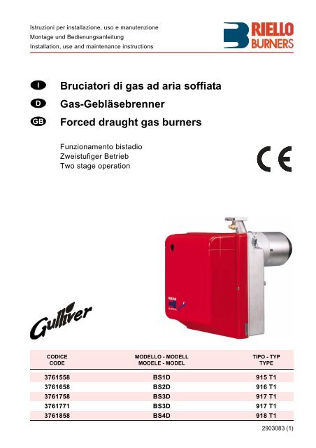
Istruzioni per installazione, uso e manutenzioneMontage und Be<strong>di</strong>enungsanleitungInstallation, use and maintenance instructionsIDGB<strong>Bruciatori</strong> <strong>di</strong> <strong>gas</strong> <strong>ad</strong> <strong>aria</strong> <strong>soffiata</strong><strong>Gas</strong>-GebläsebrennerForced draught <strong>gas</strong> burnersFunzionamento bista<strong>di</strong>oZweistufiger BetriebTwo stage operationCODICECODEMODELLO - MODELLMODELE - MODELTIPO - TYPTYPE3761558 BS1D 915 T13761658 BS2D 916 T13761758 BS3D 917 T13761771 BS3D 917 T13761858 BS4D 918 T12903083 (1)
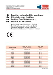
DICHIARAZIONE DEL COSTRUTTORERIELLO S.p.A. <strong>di</strong>chiara che i seguenti prodotti rispettano i valori limite degli NOx imposti dallanormativa 1. BImSchV, Agosto 2001, § 7 (2):ERKLÄRUNG DES HERSTELLERSRIELLO S.p.A. erklärt, dass <strong>di</strong>e folgenden Produkte <strong>di</strong>e Nox-Emissionsgrenzwerte gemäß derdeutschen Vorschrift 1. BImSchV, 2. August 2001, § 7 (2) respektieren:PRODUCER DECLARATIONRIELLO S.p.A. declares, that the following products comply with the NOx limit valuesin<strong>di</strong>cated in the 1. BImSchV. 1996 § 7 (2) standard.Prodotto - ProduktreiheProduct<strong>Bruciatori</strong> <strong>di</strong> <strong>gas</strong> <strong>ad</strong> <strong>aria</strong> <strong>soffiata</strong><strong>Gas</strong>-GebläsebrennerForced draught <strong>gas</strong> burnersTipo -TypType915 T1916 T1917 T1918 T1Modello - AusführungModelBS1DBS2DBS3DBS4DRIELLO S.p.A.3083
1. DESCRIZIONE DEL BRUCIATOREBruciatore <strong>di</strong> <strong>gas</strong> con funzionamento bista<strong>di</strong>o.➤ Il bruciatore risponde al gr<strong>ad</strong>o <strong>di</strong> protezione IP X0D (IP 40) secondo EN 60529.➤ Marcatura CE secondo <strong>di</strong>rettiva <strong>gas</strong> 90/396/EEC; PIN 0085AQ0409.Conforme alle Direttive: CEM 89/336/CEE, Bassa Tensione 73/23/CEE e Macchine 98/37/CEE.➤ Rampa <strong>gas</strong> conforme a EN 676.➤ Il bruciatore è omologato per funzionamento intermittente secondo la Normativa EN 676.➤ Approvazione BUWAL N° 100010.➤ Nota per la Svizzera. Devono essere osservate le prescrizioni svizzere, quelle SVGW per l’impiego del<strong>gas</strong>, quelle cantonali e locali, così come le prescrizioni dei Vigili del Fuoco (VKF).Fig. 17486035991021D71091 – Pressostato <strong>aria</strong>2 – Presa 6 poli per rampa3 – Apparecchiatura con presa 7 poli incorporata4 – Pulsante <strong>di</strong> sblocco con segnalazione <strong>di</strong> blocco5 – Gruppo porta testa6 – Presa <strong>di</strong> pressione7 – Flangia con schermo isolante8 – Gruppo regolazione serranda <strong>aria</strong>9 – Servomotore serranda <strong>aria</strong>10 – Presa 4 poli per 2° sta<strong>di</strong>o1.1 MATERIALE A CORREDOFlangia con schermo isolante . . . . . N° 1 Viti e da<strong>di</strong> per flangia <strong>di</strong> fissaggio alla caldaia . . . . N° 4Vite e d<strong>ad</strong>o per flangia . . . . . . . . . . N° 1 Spina 7 poli . . . . . . . . . . . . . . . . . . . . . . . . . . . . . . N° 1Spina 4 poli . . . . . . . . . . . . . . . . . . . N° 1 Collegamento sblocco remoto . . . . . . . . . . . . . . . . N° 11.2 ACCESSORIKIT DIAGNOSTICA SOFTWAREE’ <strong>di</strong>sponibile un kit speciale che identifica la vita del bruciatore me<strong>di</strong>ante collegamento ottico a PC in<strong>di</strong>candoneore <strong>di</strong> funzionamento, numero e tipologie <strong>di</strong> blocchi, numero <strong>di</strong> serie dell’apparecchiatura etc…Per visualizzare la <strong>di</strong>agnostica procedere come segue:➤ Collegare all’apposita presa dell’apparecchiatura il kit fornito separatamente.La lettura delle informazioni avviene dopo l’avviamento del programma software compreso nel kit.KIT SBLOCCO REMOTOIl brucitore è corredato <strong>di</strong> un kit <strong>di</strong> sblocco remoto (RS) composto da un collegamento al quale si può connettereun pulsante fino <strong>ad</strong> una <strong>di</strong>stanza massima <strong>di</strong> 20 metri.Per l’installazione, togliere il blocchetto <strong>di</strong> protezione pre<strong>di</strong>sposto in fabbrica ed inserire quello fornito acorredo del bruciatore (ve<strong>di</strong> schema elettrico a pag. 8).KIT ROTAZIONE MULTIBLOCE’ <strong>di</strong>sponibile un kit speciale che consente <strong>di</strong> installare il bruciatore ruotato <strong>di</strong> 180°, come raffigurato apagina 5 nella posizione 5 del paragrafo “3.1 POSIZIONE DI FUNZIONAMENTO”. Tale kit garantisce il correttofunzionamento della valvola della rampa <strong>gas</strong>.Il kit deve essere installato in conformità alle leggi e alle normative locali.30832 I
2. DATI TECNICI2.1 DATI TECNICITIPO 915 T1 916 T1 917 T1 918T1Potenza termica (1)secondo EN 676Potenza termica (1)secondo LRV 92<strong>Gas</strong> naturale (Famiglia 2)MotorekW 16/19 ÷ 52 35/40 ÷ 91 65/75 ÷ 189 110/140 ÷ 246Mcal/h 13,8/16,3 ÷ 44,7 30,1/34,4 ÷ 78,2 55,9/64,5 ÷ 162,5 94,6/120,4 ÷ 211,6kW 22/29 ÷ 49 40/47 ÷ 88 65/80 ÷ 180 113/148 ÷ 250Mcal/h 18,9/24,9 ÷ 42,1 34,4/40,4 ÷ 75,7 55,9/68,8 ÷ 154,8 97,2/127,3 ÷ 215Pci: 8 ÷ 12 kWh/m 3 = 7000 ÷ 10.340 kcal/m 3Pressione: min. 20 mbar – max. 100 mbar0,8A assorbiti2750 g/min.288 r<strong>ad</strong>/s1,8A assorbiti2800 g/min.294 r<strong>ad</strong>/s1,9A assorbiti2720 g/min.288 r<strong>ad</strong>/sCondensatore 4 µF 6,3 µF 8 µFAlimentazione elettrica Monofase, 230V ± 10% ~ 50HzTrasformatore d’accensione Primario 230V - 0,2A – Secondario 8 kV - 12 mAPotenza elettrica assorbita 0,15 kW 0,18 kW 0,35 kW 0,53 kW(1) Con<strong>di</strong>zioni <strong>di</strong> riferimento: Temperatura 20°C - Pressione barometrica 1013 mbar – Altitu<strong>di</strong>ne 0 m s.l.m.Per <strong>gas</strong> della famiglia 3 (GPL) richiedere kit a parte.PAESE AT - IT - DK - CH GB - IE DE FR NL LU BECATEGORIA GAS II2H3B/P II2H3P II2ELL3B/P II2Er3P II2L3B/P II2E3B/P I2E(R)B,I3PPRESSIONEGASG20 H 20 – – – – – –G25 L – 25 20 – 25 25 –G20 E – – 20 20/25 – – 20/252.2 DIMENSIONIFANGHDET45°45°MBC11Pø LOIRSD4475TIPO A B C D E F G H I L - T M N O P R S915T1 234 254 295 122,0 112,0 346 230 ÷ 276 116 ÷ 70 174 89 210 192 66 167 140 170916T1 255 280 325 125,5 125,5 352 238 ÷ 252 114 ÷ 100 174 106 230 192 66 167 140 170917T1 300 345 391 150,0 150,0 390 262 ÷ 280 128 ÷ 110 196 129 285 216 76,5 201 160 190918T1 300 345 392 150,0 150,0 446 278 ÷ 301 168 ÷ 145 216 137 286 218 80,5 203 170 20030833 I
CORRELAZIONE TRA PRESSIONE DEL GAS E POTENZIALITÀPer avere la massima potenzialità occorrono 9,3 mbar, relativamente al modello 916T1, misurati al manicotto(M2, ve<strong>di</strong> cap. 3.6, pag. 7) con camera <strong>di</strong> combustione a 0 mbar e <strong>gas</strong> G20 – Pci = 10 kWh/m3 (8.570 kcal/m3).Pressione <strong>gas</strong> alla testa<strong>di</strong> combustione in mbarD52071086420915T1916T1917T1918T10 50 100 150 200 250 kW0 50.000 100.000 150.000200.000Potenza termicakcal/h3. INSTALLAZIONEL’INSTALLAZIONE DEL BRUCIATORE DEVE ESSERE EFFETTUATA IN CONFORMITÀ ALLE LEGGI ENORMATIVE LOCALI.3.1 POSIZIONE DI FUNZIONAMENTOIl bruciatore è pre<strong>di</strong>sposto esclusivamente per il funzionamento nella posizione 1.Le installazioni nelle posizioni 2, 3, 5, 6, 7 non garantiscono la chiusura della serranda <strong>aria</strong> in sosta.L’installazione nella posizione 5 é possibile solamente tramite il “Kit rotazione MULTIBLOC” da or<strong>di</strong>narsi separatamente.L’installazione 4 è vietata per motivi <strong>di</strong> sicurezza.1 2 3 45 6 7D445030835 I
3.2 FISSAGGIO ALLA CALDAIAPer installare il bruciatore alla caldaia è necessario effettuare le seguenti operazioni:➤ Allargare, se necessario, i fori dello schermo isolante (3, fig. 3).➤ Fissare alla portina della caldaia (1) la flangia (5) me<strong>di</strong>ante le quattro viti (4) e (se necessario) i da<strong>di</strong> (2)interponendo lo schermo isolante (3) ma tenendo allentata una delle due viti superiori (4), (ve<strong>di</strong> fig. 2).➤ Infilare la testa <strong>di</strong> combustione del bruciatore nella flangia (5), stringere la flangia con la vite (6), quin<strong>di</strong>bloccare la vite (4) rimasta allentata.N.B.: Il bruciatore può essere fissato con la quota (A) v<strong>aria</strong>bile (ve<strong>di</strong> fig. 4). Assicurarsi comunque che latesta <strong>di</strong> combustione attraversi tutto lo spessore della portina della caldaia.Fig. 2Fig. 3D5012AFig. 4S7002TIPO A915 T1 116 ÷ 70916 T1 114 ÷ 100917 T1 128 ÷ 110918 T1 167,5 ÷ 145D50113.3 POSIZIONAMENTO SONDA ELETTRODOATTENZIONE➤ Assicurarsi che la piastrina (3, fig. 5) sia sempreinserita nella spianatura dell’elettrodo (1).➤ Appoggiare l’isolatore della sonda (4) allatazza (2).TIPO 915T1 916T1 917T1 918T1A 17 30 31 313,5 ± 0,3 A1± 0,3Fig. 52D60883430836 I
3.7 COLLEGAMENTI ELETTRICIAPPARECCHIATURAMG569LEGENDAB5 – Spia bloccoC – CondensatoreCN1 – Connettore sondaE – Elettrodoh.. – ContaoreMV – MotorePA – Pressostato <strong>aria</strong> min.PG – Pressostato <strong>gas</strong> min.RS – Reset remotoSM – Servomotore serranda<strong>aria</strong>SO – Sonda ionizzazioneS3 – Spia blocco(230V - 0,5 A max)T6A – FusibileTB – Terra bruciatoreTL – Termostato limiteTR – Termostato <strong>di</strong> regolazioneTS – Termostato <strong>di</strong> sicurezzaV10 – Valvola <strong>di</strong> sicurezzaV11 – Valvola 1° sta<strong>di</strong>oV12 – Valvola 2° sta<strong>di</strong>oX.. – SpinaXP.. – PresaBluMarroneNeroD4627ESEGUITOIN FABBRICAA CURADELL’INSTALLATOREFig. 8InterruttoregeneraleA230V ~ 50HzE9250ATTENZIONE:➤ Non scambiare il neutro con la fase, rispettare esattamente loschema in<strong>di</strong>cato ed eseguire un buon collegamento <strong>di</strong> terra.➤ La sezione dei conduttori deve essere <strong>di</strong> min. 1 mm 2 . (Salvo <strong>di</strong>verse in<strong>di</strong>cazioni<strong>di</strong> norme e leggi locali).➤ I collegamenti elettrici eseguiti dall’installatore devono rispettare le normevigenti nel paese.● Collegare il termostato 2° sta<strong>di</strong>o (TR) ai morsetti T6 - T8 togliendoil ponte.COLLAUDO➤ Verificare l’arresto del bruciatore aprendo i termostati.➤ Verificare il blocco del bruciatore aprendo il connettore (CN1) inseritonel filo rosso della sonda, posto all’esterno dell’apparecchiatura.APPARECCHIATURA, (ve<strong>di</strong> fig. 8)Per estrarre l’apparecchiatura dal bruciatore è necessario:➤ sconnettere tutti i connettori <strong>ad</strong> essa collegati, la spina a 7 poli, i cavi <strong>di</strong> altatensione ed il filo <strong>di</strong> terra (TB);➤ svitare la vite (A, fig. 8) e tirare l’apparecchiatura nel senso della freccia.Per l’installazione dell’apparecchiatura è necessario:➤ avvitare la vite (A) con una coppia <strong>di</strong> serraggio da 1 ÷ 1,2 Nm;➤ connettere tutti connettori precedentemente scollegati.NOTE:I bruciatori sono stati omologati per funzionamento intermittente. Ciò significa chedevono fermarsi almeno 1 volta ogni 24 ore per permettere all’apparecchiatura elettrica<strong>di</strong> effettuare un controllo della propria efficienza all’avviamento. Normalmentel’arresto del bruciatore viene assicurato dal termostato limite (TL) della caldaia. Secosì non fosse, è necessario applicare in serie al termostato limite (TL) un interruttoreorario che provveda all’arresto del bruciatore almeno una volta ogni 24 ore.30838 I
4. FUNZIONAMENTO4.1 REGOLAZIONE DELLA COMBU-STIONEIn conformità con la Direttiva Ren<strong>di</strong>mento92/42/CEE, l’applicazione del bruciatore allacaldaia, la regolazione e il collaudo, devonoessere eseguiti nell’osservanza del manualed’istruzione della caldaia stessa, compreso ilcontrollo della concentrazione <strong>di</strong> CO e CO 2nei fumi, della loro temperatura e <strong>di</strong> quella me<strong>di</strong><strong>ad</strong>ell’acqua della caldaia.A seconda della portata richiesta dalla caldaiava definita la regolazione della testa <strong>di</strong> combustionee la regolazione della serranda <strong>aria</strong>.Fig. 94.2 REGOLAZIONE TESTA DI COM-BUSTIONE, (ve<strong>di</strong> fig. 9)La sua regolazione v<strong>aria</strong> in base alla portat<strong>ad</strong>el bruciatore. Si esegue ruotando in sensoorario o antiorario la vite <strong>di</strong> regolazione (6) finoa che la tacca incisa sulla staffa <strong>di</strong> regolazione(2) coincide con il piano esterno delgruppo testa (1). Nella figura 9, la staffa <strong>di</strong> regolazionedella testa è tarata alla tacca 3.Esempio per bruciatore BS3D:Il bruciatore è installato in una caldaia da100 kW. Considerando un ren<strong>di</strong>mento del 90%il bruciatore dovrà erogare circa 110 kW con laregolazione della staffa a tacca 3, come illustratonel <strong>di</strong>agramma.Il <strong>di</strong>agramma è orientativo; per garantire lemigliori prestazioni del bruciatore si consiglia<strong>di</strong> regolare la testa in funzione delle esigenzerichieste dal tipo <strong>di</strong> caldaia.ESTRAZIONE GRUPPO TESTAPer l’estrazione del gruppo testa eseguire leseguenti operazioni:➤ Sconnettere i collegamenti (3 e 5).➤ Sfilare il tubetto (4) e allentare le viti (10).➤ Svitare e togliere le viti (7), estrarre il gruppoporta testa (1) apportando una lieve rotazioneverso destra.Si raccomanda <strong>di</strong> non alterare la posizione<strong>di</strong> regolazione staffa-gomito (2) nella fase<strong>di</strong> smontaggio.kcal/h210.000170.000130.00090.00050.000kW250230210190170150130110907050S7006917T1916T1915T1918T1D5210RIMONTAGGIO GRUPPO TESTARimontare con procedura inversa a quantosopra descritto, riposizionando il gruppo testa(1) come in origine.10.0000 2 4 6 8TaccaATTENZIONE➤ Avvitare le viti (7) (senza bloccarle) fino a battuta; quin<strong>di</strong> bloccarle con una coppia <strong>di</strong> serraggio <strong>di</strong> 3 - 4 Nm.➤ Controllare che, durante il funzionamento, non si verifichino per<strong>di</strong>te <strong>di</strong> <strong>gas</strong> dalle se<strong>di</strong> delle viti.➤ Qualora accidentalmente si allentasse la presa <strong>di</strong> pressione (13) si raccomanda il corretto fissaggio assicurandosiche il foro (F) posto nella parte interna del gruppo testa (1) sia rivolto verso il basso.30101030839 I
4.3 REGOLAZIONE SERRANDA ARIA, (fig. 10)Il primo avviamento deve sempre essere effettuato, agendo sullavite (12), in modo che l’in<strong>di</strong>ce della posizione serranda <strong>aria</strong> <strong>di</strong> 1°sta<strong>di</strong>o sia superiore a tacca 1, (taratura <strong>di</strong> fabbrica tacca 1).Per effettuare la regolazione procedere come segue:➤ Portare il bruciatore in 2° sta<strong>di</strong>o chiudendo il collegamento T6-T8presente nella spina 4 poli (X4, collegamenti elettrici <strong>di</strong> pagina 8).➤ La serranda <strong>aria</strong> per effetto della spinta del ventilatore si portanella posizione <strong>di</strong> 2° sta<strong>di</strong>o relativa alla taratura <strong>di</strong> fabbrica (vite 8su tacca 3).➤ Allentare il d<strong>ad</strong>o (9) e agire sulla vite (8) per regolare la portata <strong>di</strong><strong>aria</strong> <strong>di</strong> 2° sta<strong>di</strong>o (ve<strong>di</strong> valori <strong>di</strong> CO 2 riportati nella tabella sottostante).➤ Portare il bruciatore in 1° sta<strong>di</strong>o aprendo il collegamento T6-T8,presente nella spina 4 poli (X4, pag. 8).➤ Regolare il 1° sta<strong>di</strong>o agendo sulla vite (12) dopo aver allentato(senso orario) il d<strong>ad</strong>o (11) facendo riferimento alla tabella sottostanteper i valori <strong>di</strong> CO 2 .➤ Una volta raggiunta la regolazione ottimale bloccare (sensoantiorario) il d<strong>ad</strong>o (11). All’arresto del bruciatore, la serranda <strong>aria</strong>per effetto del suo peso, si chiude automaticamente, fino <strong>ad</strong> una depressione massima al camino <strong>di</strong> 0,5 mbar.ATTENZIONEFig. 10Per la regolazione della potenzialità del 1° e 2° sta<strong>di</strong>o rispettare le seguenti in<strong>di</strong>cazioni:Il rapporto <strong>di</strong> potenzialità tra 1° e 2° sta<strong>di</strong>o deve essere al massimo <strong>di</strong> 1:2.Esempio per BS3D: Potenza richiesta <strong>di</strong> 2° sta<strong>di</strong>o 140 kW;Potenza minima <strong>di</strong> 1° sta<strong>di</strong>o non inferiore a 70 kW.In ogni caso la potenzialità minima del bruciatore <strong>di</strong> 1° sta<strong>di</strong>o non deve essere inferiore al valore in<strong>di</strong>catonel campo <strong>di</strong> lavoro.Esempio per BS3D: Potenza richiesta <strong>di</strong> 2° sta<strong>di</strong>o 110 kW;Potenza minima <strong>di</strong> 1° sta<strong>di</strong>o non inferiore a 65 kW (minimo del campo <strong>di</strong> lavoro pag. 4).01234568911124.4 CONTROLLO DELLA COMBUSTIONEÈ consigliabile regolare il bruciatore, a seconda del tipo <strong>di</strong> <strong>gas</strong> utilizzato, secondo le in<strong>di</strong>cazioni fornitenella tabella seguente:EN 676 ECCESSO D’ARIA: potenza max. λ ≤ 1,2 – potenza min.λ ≤ 1,3GASCO 2 max. teoricoTaratura CO 2 % CONO x0 % O 2 λ = 1,2 λ = 1,3 mg/kWh mg/kWhG 20 11,7 9,7 9,0 ≤ 100 ≤ 170G 25 11,5 9,5 8,8 ≤ 100 ≤ 170G 30 14,0 11,6 10,7 ≤ 100 ≤ 230G 31 13,7 11,4 10,5 ≤ 100 ≤ 230CORRENTE DI IONIZZAZIONELa corrente minima per far funzionare l’apparecchiaturaè 5 µA.Il bruciatore dà una corrente nettamente superiore,tale da non richiedere normalmentealcun controllo. Qualora, comunque, si vogliamisurare la corrente <strong>di</strong> ionizzazione bisognaaprire il connettore (CN1, ve<strong>di</strong> schema elettricopag. 8) inserito nel filo rosso ed inserireun microamperometro.+CN1D4631_SO308310 I
4.5 PRESSOSTATO ARIAEseguire la regolazione del pressostato <strong>aria</strong> dopo aver effettuato tutte le altre regolazioni del bruciatorecon il pressostato <strong>aria</strong> regolato a inizio scala. Con il bruciatore funzionante alla potenza richiesta, ruotare lamanopola lentamente in senso orario fino al blocco del bruciatore. Ruotare quin<strong>di</strong> in senso antiorario lamanopola <strong>di</strong> una tacca e ripetere l’avviamento del bruciatore per verificarne la regolarità. Se il bruciatore siblocca nuovamente, ruotare ancora la manopola <strong>di</strong> mezza tacca.ATTENZIONE:Per norma il pressostato <strong>aria</strong> deve intervenire quando il CO nei fumi supera l’ 1% (10.000 ppm). Per accertarsi<strong>di</strong> ciò, inserire un analizzatore della combustione nel camino, chiudere lentamente la bocca <strong>di</strong> aspirazionedel ventilatore e verificare che avvenga il blocco del bruciatore, prima che il CO nei fumi superi l’ 1%.4.6 PROGRAMMA DI AVVIAMENTOTermostatoMotoreTrasf. d’accensionePrima valvolaPrima fiammaSeconda valvolaSeconda fiammaBloccoNormaleBlocco per mancata accensioneA40s min.40s min.3s max.D50165 ÷ 25s3s max.ASegnalato dalla spia sull’apparecchiatura <strong>di</strong> comando e controllo (4, fig. 1, pag. 2).4.7 FUNZIONE DI RICICLOL’apparecchiatura permette il riciclo, ossia la ripetizione completa del programma <strong>di</strong> avviamento, per unmassimo <strong>di</strong> 3 tentativi nel caso in cui la fiamma si spegne in funzionamento.4.8 FUNZIONE DI POST-VENTILAZIONELa post-ventilazione è una funzione che mantiene la ventilazione dell’<strong>aria</strong> anche dopo lo spegnimento delbruciatore. Lo spegnimento del bruciatore avviene all’apertura del termostato limite (TL) con la conseguenteinterruzione dell’apporto <strong>di</strong> combustibile delle valvole.Per utilizzare questa funzione è necessario agire sul pulsante <strong>di</strong> sblocco quando il termostato limite (TL)non è commutato (BRUCIATORE SPENTO).Il tempo <strong>di</strong> post-ventilazione può essere impostato per un massimo <strong>di</strong> 6 minuti, procedendo come segue:➤ Premere il pulsante <strong>di</strong> sbocco per 5 secon<strong>di</strong> almeno, finchè il led <strong>di</strong> segnalazione <strong>di</strong>venta rosso.➤ Impostare il tempo desiderato premendo il pulsante più volte: 1 volta = 1 minuto <strong>di</strong> post-ventilazione.➤ Dopo 5 secon<strong>di</strong> l’apparecchiatura segnalerà automaticamente i minuti impostati tramite i lampeggi delled rosso: 1 lampeggio = 1 minuto <strong>di</strong> post-ventilazione.Per resettare tale funzione è sufficiente premere il pulsante per 5 secon<strong>di</strong> finchè il led <strong>di</strong> segnalazione<strong>di</strong>venta rosso e rilasciarlo senza eseguire nessuna operazione, poi attendere almeno 20 secon<strong>di</strong> per farripartire il bruciatore.Se durante la post-ventilazione vi è una nuova richiesta <strong>di</strong> calore, alla commutazione del termostato limite(TL) il tempo <strong>di</strong> post-ventilazione si interrompe e inizia un nuovo ciclo <strong>di</strong> funzionamento del bruciatore.L’apparecchiatura esce dalla fabbrica con la seguente impostazione: 0 minuti = no post-ventilazione.4.9 SBLOCCO APPARECCHIATURAPer effettuare lo sblocco dell’apparecchiatura procedere come segue:➤ Premere il pulsante <strong>di</strong> sblocco per almeno 1 secondo.Nel caso in cui il bruciatore non riparta è necessario verificare la chiusura del termostato limite (TL).308311 I
5. MANUTENZIONEPrima <strong>di</strong> effettuare qualsiasi operazione <strong>di</strong> pulizia o controllo, togliere líalimentazione elettrica al bruciatoreagendo sullíinterruttore generale dellíimpianto e chiudere la valvola <strong>di</strong> intercettazione del <strong>gas</strong>.Il bruciatore richiede una manutenzione perio<strong>di</strong>ca, che deve essere eseguita da personale abilitato e in conformitàalle leggi e normative locali.La perio<strong>di</strong>ca manutenzione è essenziale per un buon funzionamento del bruciatore; evita in questo modo consumiinutili <strong>di</strong> combustibile e riduce le emissioni inquinanti nellíambiente.LE OPERAZIONI BASILARI DA EFFETTUARE SONO LE SE-Fig. 11GUENTI:➤ Verificare perio<strong>di</strong>camente la possibile ostruzione dei fori del <strong>di</strong>stributore<strong>gas</strong> e, se necessario, pulire con un utensile appuntitocome illustrato nella figura 11.➤ Verificare che non ci siano occlusioni o strozzature nei tubi <strong>di</strong> alimentazionee ritorno del combustibile, nelle zone <strong>di</strong> aspirazione<strong>aria</strong> e nei condotti <strong>di</strong> evacuazione dei prodotti della combustione.➤ Verificare la corretta esecuzione dei collegamenti elettrici delbruciatore e della rampa <strong>gas</strong>.➤ Verificare il corretto posizionamento della presa <strong>di</strong> pressione(6, fig. 1, pag. 2).➤ Verificare che la rampa <strong>gas</strong> sia idonea alla potenzialità del bruciatore,al tipo <strong>di</strong> <strong>gas</strong> utilizzato ed alla pressione <strong>gas</strong> della rete.➤ Verificare il corretto posizionamento della testa <strong>di</strong> combustionee del suo fissaggio alla caldaia.E9252➤ Verificare il corretto posizionamento della serranda <strong>aria</strong>.➤ Verificare il corretto posizionamento della sonda <strong>di</strong> ionizzazione e dell'elettrodo (ve<strong>di</strong> fig. 5, pag. 6).➤ Verificare la regolazione del pressostato <strong>aria</strong> e del pressostato <strong>gas</strong>.Lasciare funzionare il bruciatore a pieno regime per circa <strong>di</strong>eci minuti, controllando le corrette tarature in 1° e 2°sta<strong>di</strong>o <strong>di</strong> tutti gli elementi in<strong>di</strong>cati nel presente manuale.Quin<strong>di</strong> effettuare un’analisi della combustione verificando:● Percentuale <strong>di</strong> CO2 (%); ● Contenuto <strong>di</strong> CO (ppm); ● Contenuto NOx (ppm);● Corrente <strong>di</strong> ionizzazione (µA); ● Temperatura dei fumi al camino.5.1 DIAGNOSTICA VISIVA APPARECCHIATURAL’apparecchiatura in dotazione ha una funzione <strong>di</strong>agnostica attraverso la quale è possibile in<strong>di</strong>viduare leeventuali cause <strong>di</strong> mal funzionamento (segnalazione: LED ROSSO).Per utilizzare tale funzione, è necessario premere il pulsante <strong>di</strong> sblocco per almeno 3 secon<strong>di</strong> dall’istante <strong>di</strong>messa in sicurezza (blocco).L’apparecchiatura genera una sequenza <strong>di</strong> impulsi che si ripete <strong>ad</strong> intervalli costanti <strong>di</strong> 2 secon<strong>di</strong>.LED ROSSO accesopremere sblocco per 3sLampeggiIntervallo2sLampeggi La sequenza degli impulsi emessi dall’apparecchiatura identifica le possibili tipologie <strong>di</strong> guasto che vengonoelencate nella seguente tabella.2 lampeggi3083SEGNALE12 ICAUSA PROBABILENon viene rilevato un segnale stabile <strong>di</strong> fiamma alla fine del tempo <strong>di</strong> sicurezza:– guasto alla sonda <strong>di</strong> ionizzazione;– guasto alla valvola <strong>gas</strong>;– inversione fase/neutro;– guasto al trasformatore <strong>di</strong> accensione;– bruciatore non regolato (<strong>gas</strong> insufficiente).
3 lampeggi4 lampeggiSEGNALE6 lampeggi7 lampeggiCAUSA PROBABILEPressostato <strong>aria</strong> <strong>di</strong> minima non chiude o è già chiuso prima della chiusura deltermostato limite:– guasto al pressostato <strong>aria</strong>;– pressostato <strong>aria</strong> non regolato;Luce presente in camera prima dell’accensione e allo spegnimento del bruciatore:– presenza <strong>di</strong> luce estranea prima o dopo la commutazione del termostato limite;– presenza <strong>di</strong> luce estranea durante la pre-ventilazione;– presenza <strong>di</strong> luce estranea durante la post-ventilazione.Per<strong>di</strong>ta <strong>aria</strong> <strong>di</strong> ventilazione:– per<strong>di</strong>ta <strong>aria</strong> durante la pre-ventilazione;– per<strong>di</strong>ta <strong>aria</strong> durante o dopo il tempo <strong>di</strong> sicurezza.Sparizione della fiamma durante il funzionamento:– bruciatore non regolato (<strong>gas</strong> insufficiente);– guasto alla valvola <strong>gas</strong>;– cortocircuito tra la sonda <strong>di</strong> ionizzazione e la terra.ATTENZIONEPer resettare l’apparecchiatura dopo la visualizzazione della <strong>di</strong>agnostica visiva ènecessario premere il pulsante <strong>di</strong> sblocco.6. ANOMALIE / RIMEDISi elencano alcune cause e i possibili rime<strong>di</strong> a una serie <strong>di</strong> anomalie che potrebbero verificarsi e portare <strong>ad</strong> unmancato o non regolare funzionamento del bruciatore. Un’anomalia, nel funzionamento nella maggior parte deicasi, porta alla accensione della segnalazione all’interno del pulsante <strong>di</strong> sblocco dell’apparecchiatura <strong>di</strong>comando e controllo (4, fig. 1, pag. 2). All’accendersi <strong>di</strong> questo segnale, il bruciatore potrà funzionare nuovamentesolo dopo aver premuto a fondo il pulsante <strong>di</strong> sblocco; fatto ciò, se avviene un’accensione regolare, sipuò imputare l’arresto <strong>ad</strong> una anomalia transitoria e non pericolosa. Al contrario, se il blocco persiste si dovràricercare la causa dell’anomalia e attuare i rime<strong>di</strong> illustrati nella tabella seguente.6.1 DIFFICOLTÀ DI AVVIAMENTOANOMALIE POSSIBILE CAUSA RIMEDIOIl bruciatore non partealla chiusura del termostatolimite.3083Manca l’alimentazione elettrica.Manca <strong>gas</strong>.Il pressostato <strong>gas</strong> non chiude il contatto.Le connessioni dell’apparecchiaturaelettronica non sono correttamente inserite.Il pressostato <strong>aria</strong> è commutato in posizione<strong>di</strong> funzionamento.13 IVerificare presenza tensione ai morsettiL1 – N della spina 7 poli.Verificare lo stato dei fusibili.Verificare che il termostato <strong>di</strong> sicurezzanon sia in blocco.Verificare l’apertura della saracinesca.Verificare che le valvole abbiano commutatoin posizione aperto e che non visiano corticircuiti.Provvedere <strong>ad</strong> una sua regolazione.Controllare e connettere a fondo tutte leprese.Sostituire il pressostato.
ANOMALIE POSSIBILE CAUSA RIMEDIOIl brucitore tende astrappare la fiamma nelpassaggio da 1° a 2° sta<strong>di</strong>o.Il bruciatore eseguenormalmente il ciclo <strong>di</strong>preventilazione ed accensionee si blocc<strong>ad</strong>opo circa 3s.Avviamento del bruciatorecon ritardo <strong>di</strong> accensione.Il bruciatore non commutain 2° sta<strong>di</strong>o.Il bruciatore va in bloccodopo la fase <strong>di</strong> preventilazioneperchè lafiamma non si accende.Il bruciatore va in bloccoin fase <strong>di</strong> preventilazione.3083Rapporto <strong>di</strong> potenzialità tra 1° e 2° sta<strong>di</strong>osuperiore a 1:2.Eccesso d’<strong>aria</strong> elevato in 1° sta<strong>di</strong>o.È invertito il collegamento fase-neutro.Manca o è inefficace il collegamento<strong>di</strong> terra.La sonda <strong>di</strong> ionizzazione è a massa onon è immersa nella fiamma o è interrottoil suo collegamento con l’apparecchiaturao questo presenta <strong>di</strong>fetto <strong>di</strong>isolamento verso massa.L’elettrodo <strong>di</strong> accensione è malposizionato.Portata dell’<strong>aria</strong> troppo elevata.Freno valvola troppo chiuso con insufficienteuscita <strong>di</strong> <strong>gas</strong>.Il servomotore è bloccato.La valvola <strong>gas</strong> 2° sta<strong>di</strong>o non sieccita.Le elettrovalvole fanno passaretroppo poco <strong>gas</strong>.Le elettrovalvole sono <strong>di</strong>fettose.Manca o è irregolare l’arco elettrico <strong>di</strong>accensione.Presenza <strong>di</strong> <strong>aria</strong> nella tubazione.Il pressostato <strong>aria</strong> non commuta ilcontatto.La fiamma è esistente.La presa <strong>di</strong> pressione (13, fig. 9, pag.9) è mal posizionata.14 IRipristinare il corretto rapporto massimo <strong>di</strong>1:2 controllando che la potenzialità del 1°sta<strong>di</strong>o non sia inferiore al minimo delcampo <strong>di</strong> lavoro.Ripristinare il corretto valore <strong>di</strong> aeccesso<strong>di</strong> <strong>aria</strong> (λ min. = 1.3) ve<strong>di</strong> paragrafo “4.4controllo della combustione”.Provvedere <strong>ad</strong> un loro scambio.Provvedere a renderlo efficiente.Verificare la corretta posizione ed eventualmenteaggiustarla secondo quanto in<strong>di</strong>catoin questo manuale.Ripristinare il collegamento elettrico.Sostituire il collegamento <strong>di</strong>fettoso.Provvedere a una una corretta regolazionesecondo quanto in<strong>di</strong>cato in questomanuale.Regolare la portata dell’<strong>aria</strong> secondoquanto in<strong>di</strong>cato in questo manuale.Effettuare una corretta regolazione.Verificare la sua corretta funzionalità.Verificare l’esatto collegamento elettrico.Valvola guasta: provvedere a una suasostituzione.Il servomotore non arriva a fine corsa equin<strong>di</strong> non eccita il micro <strong>di</strong> consenso valvola2° sta<strong>di</strong>o: verificare la bontà del micro.Verificare la pressione in rete e/o regolarele elettrovalvole come in<strong>di</strong>cato inquesto manuale.Procedere <strong>ad</strong> una loro sostituzione.Verificare il corretto inserimento dei connettori.Verificare l’esatta posizione dell’elettrodosecondo quanto in<strong>di</strong>cato in questomanuale.Provvedere <strong>ad</strong> uno sfiatamento completodella linea <strong>di</strong> alimentazione del <strong>gas</strong>.Il pressostato è <strong>di</strong>fettoso; provvedere <strong>ad</strong>una sua sostituzione.La pressione dell’<strong>aria</strong> è troppo bassa(testa mal regolata).Valvole <strong>di</strong>fettose: provvedere alla lorosostituzione.Effettuare un corretto posizionamentosecondo quanto descritto in questo manualeal capitolo 4.2 pag. 9.
ANOMALIE POSSIBILE CAUSA RIMEDIOIl bruciatore continua aripetere il ciclo <strong>di</strong> avviamentosenza che intervengail blocco.La pressione del <strong>gas</strong> in rete è moltoprossima al valore sul quale è regolatoil pressostato <strong>gas</strong>. Il calo <strong>di</strong> pressionerepentino che si ha all’apertura dellavalvola, provoca l’apertura del pressostatostesso, per cui la valvola richiudesubito e si ferma il motore. Lapressione torna poi <strong>ad</strong> aumentare, ilpressostato richiude e fa ripartire il ciclo<strong>di</strong> avviamento e così via.Abbassare la regolazione della pressionedel pressostato.6.2 ANOMALIE IN FUNZIONAMENTOANOMALIA POSSIBILE CAUSA RIMEDIOIl bruciatore va inblocco in funzionamento.Arresto del bruciatore.Sonda a massa.Sparizione della fiamma per 4 volte.Apertura pressostato <strong>aria</strong>.Apertura pressostato <strong>gas</strong>.Verificare la corretta posizione edeventualmente aggiustarla secondoquanto in<strong>di</strong>cato in questo manuale.Provvedere alla pulizia o la sostituzionedella sonda <strong>di</strong> ionizzazione.Verificare la pressione del <strong>gas</strong> in rete e/o regolare l’elettrovalvola come in<strong>di</strong>catoin questo manuale.La pressione dell’<strong>aria</strong> è troppo bassa(testa mal regolata).Il pressostato <strong>aria</strong> è <strong>di</strong>fettoso: provvederealla sua sostituzione.Verificare la pressione in rete e/o regolarel’elettrovalvola come in<strong>di</strong>cato inquesto manuale.308315 I
7. AVVERTENZE E SICUREZZAAl fine <strong>di</strong> garantire una combustione col minimo tasso <strong>di</strong> emissioni inquinanti, le <strong>di</strong>mensioni ed il tipo <strong>di</strong> camera<strong>di</strong> combustione del generatore <strong>di</strong> calore, devono corrispondere a valori ben definiti.È pertanto consigliato consultare il Servizio Tecnico <strong>di</strong> Assistenza prima <strong>di</strong> scegliere questo tipo <strong>di</strong> bruciatoreper l’abbinamento con una caldaia. Il personale abilitato è quello avente i requisiti tecnico professionaliin<strong>di</strong>cati dalla legge 5 marzo 1990 n° 46.L’organizzazione commerciale <strong>di</strong>spone <strong>di</strong> una capillare rete <strong>di</strong> agenzie e servizi tecnici il cui personale partecipaperio<strong>di</strong>camente a corsi <strong>di</strong> istruzione e aggiornamento presso il Centro <strong>di</strong> Formazione aziendale.Questo bruciatore deve essere destinato solamente all’uso per il quale è stato espressamente realizzato.È esclusa qualsiasi responsabilità contrattuale ed extracontrattuale del costruttore per danni causati a persone,animali o cose, da errori d’installazione, <strong>di</strong> regolazione, <strong>di</strong> manutenzione e da usi impropri.7.1 IDENTIFICAZIONE BRUCIATORELa Targhetta d’identificazione <strong>di</strong> prodotto riporta il numero <strong>di</strong> matricola, il modello e i principali dati tecnicoprestazionali.La manomissione, l'asportazione, la mancanza della Targhetta d’identificazione non permettela sicura identificazione del prodotto e rende <strong>di</strong>fficoltosa e/o pericolosa qualsiasi operazione <strong>di</strong> installazionee <strong>di</strong> manutenzione.7.2 REGOLE FONDAMENTALI DI SICUREZZA➤ È vietato l’uso dell’apparecchio da parte <strong>di</strong> bambini o persone inesperte.➤ È assolutamente vietato tappare con stracci, carte od altro le griglie <strong>di</strong> aspirazione o <strong>di</strong> <strong>di</strong>ssipazione el'apertura <strong>di</strong> aerazione del locale dov'è installato l'apparecchio.➤ È vietato qualsiasi tentativo <strong>di</strong> riparazione dell’apparecchio da parte <strong>di</strong> personale non autorizzato.➤ È pericoloso tirare o torcere i cavi elettrici.➤ È vietata qualsiasi operazione <strong>di</strong> pulizia prima <strong>di</strong> avere scollegato l’apparecchio dalla rete <strong>di</strong> alimentazioneelettrica.➤ Non effettuare pulizie del bruciatore né <strong>di</strong> sue parti con sostanze facilmente infiammabili (es. benzina,alcool, ecc.). La pulizia della mantellatura deve essere fatta solamente con acqua saponata.➤ Non appoggiare oggetti sul bruciatore.➤ Non tappare o ridurre <strong>di</strong>mensionalmente le aperture <strong>di</strong> aerazione del locale dov’è installato il generatore.➤ Non lasciare contenitori e sostanze infiammabili nel locale dov’è installato l’apparecchio.308316 I
1. BESCHREIBUNG DES BRENNERS<strong>Gas</strong>brenner mit zweistufigem Betrieb.➤ Der Brenner entspricht dem Schutzart IP X0D (IP 40) gemäß EN 60529.➤ CE Kennzeichnung gemäß der <strong>Gas</strong>geräterichtlinie 90/396/EWG; PIN 0085AQ0409.Gemäß Richtlinien: EMV 89/336/EWG, Niederspannungsrichtlinie 73/23/EWG und Maschinenrichtlinie98/37/EWG.➤ <strong>Gas</strong>strecke gemäß der Euronorm EN 676.➤ Der Brenner ist gemäß der Norm EN 676 für intermittierenden Betrieb typgenehmigt.➤ Zulassung BUWAL Nr. 100010.➤ Bemerkung für <strong>di</strong>e Schweiz. Es sind <strong>di</strong>e schweizerischen Vorschriften, <strong>di</strong>e SVGW-<strong>Gas</strong>leitsätze, kantonale undörtliche Vorschriften, sowie <strong>di</strong>e Vorschriften der Vereinigung Kantonaler Feuerversicherungen (VKF) zu beachten.Fig. 17486035991021D71091 – Luftdruckwächter2 – 6 - polige Steckdose für <strong>Gas</strong>strecke3 – Steuergerät mit 7 - poliger Steckdose4 – Entstörtaste mit Störanzeige5 – Kopfblock - Halter6 – Druckanschluß7 – Kesselflansch mit Isolier<strong>di</strong>chtung8 – Luftklappenregulierung9 – Stellantrieb10 – 2. Stufe 4 - polige Steckdose1.1 MITGELIEFERTES ZUBEHÖRKesselflansch mit Isolier<strong>di</strong>chtung . . .1 St. Schraube und Muttern für Brennerflansch . . . . . . . 1 St.7 poliger Stecker . . . . . . . . . . . . . . . .1 St. Schrauben und Muttern für Kesselflansch . . . . . . . 4 St.4 poliger Stecker . . . . . . . . . . . . . . . .1 St. Verbindung Fernentstörung . . . . . . . . . . . . . . . . . . 1 St.1.2 ZUBEHÖRTEILESATZ SOFTWAREDIAGNOSEZur Verfügung steht ein Spezialsatz, der <strong>di</strong>e Lebensdauer des Brenners mittels optischem Anschluss aneinen PC erkennt und seine Betriebsstunden, <strong>di</strong>e Anzahl und Typik der Störabschaltungen, <strong>di</strong>e Seriennummerdes Steuergeräts usw. angibt. Zur Ansicht der Diagnose wie folgt vorgehen:➤ Den gesondert gelieferten Satz an der dazu vorgesehenen Steckerbuchse des Steuergeräts anschließen.Die Anzeige der Informationen erfolgt nach dem Start des Softwareprogramms im Satz.SATZ FERNENTSTÖRUNGDer Brenner ist mit einem Fernentstörungssatz (RS) ausgerüstet, der aus einer Verbindung besteht, an derbis zu einer Entfernung von max. 20 Metern eine Taste angeschlossen werden kann. Zur Installation, denwerkseitig vorbereiteten Schutzblock entfernen und den mit dem Brenner gelieferten einbauen (sieheSchaltplan auf Seite 8).SATZ FÜR MULTIBLOC-DREHUNGZur Verfügung steht ein spezieller Satz, mit dem der Brenner um 180° gedreht installiert werden kann, wieauf Seite 5, Position 5, Punkt "3.1 BETRIEBSPOSITION" dargestellt. Dieser Satz gewährleistet den korrektenBetrieb des Ventils der <strong>Gas</strong>strecke. Der Satz muss in Konformität mit den örtlichen Gesetzen und Vorschrifteninstalliert werden.30832 D
2. TECHNISCHE MERKMALE2.1 TECHNISCHE DATENTYP 915 T1 916 T1 917 T1 918T1Brennerleistung(1) nach EN 676Brennerleistung(1) nach LRV 92kW 16/19 ÷ 52 35/40 ÷ 91 65/75 ÷ 189 110/140 ÷ 246Mcal/h 13,8/16,3 ÷ 44,7 30,1/34,4 ÷ 78,2 55,9/64,5 ÷ 162,5 94,6/120,4 ÷ 211,6kW 22/29 ÷ 49 40/47 ÷ 88 65/80 ÷ 180 113/148 ÷ 250Mcal/h 18,9/24,9 ÷ 42,1 34,4/40,4 ÷ 75,7 55,9/68,8 ÷ 154,8 97,2/127,3 ÷ 215Unterer Heizwert: 8 ÷ 12 kWh/m 3 = 7000 ÷ 10.340 kcal/m 3Erd<strong>gas</strong> (Familie 2)Anschlussdruck: Min. 20 mbar – Max. 100 mbarStromversorgung Einphase, 230V ± 10% ~ 50HzMotorStromaufn. 0,8A2750 U/min.288 r<strong>ad</strong>/sStromaufn. 1,8A2800 U/min.294 r<strong>ad</strong>/sStromaufn. 1,9A2720 U/min.288 r<strong>ad</strong>/sKondensator 4 µF 6,3 µF 8 µFZündtransformator Primär 230V / 0,2A – Sekundär 8 kV – 12 mALeistungsaufnahme 0,15 kW 0,18 kW 0,35 kW 0,53 kW(1) Be<strong>di</strong>ngungen: Temperatur 20°C - Luftdruck 1013 mbar – Höhe 0 m auf Meereshöhe.Für <strong>Gas</strong> der 3. <strong>Gas</strong>familie (Flüssig<strong>gas</strong>) Umstellsatz anfordern.LAND AT - IT - DK - CH GB - IE DE FR NL LU BEGASKATEGORIE II2H3B/P II2H3P II2ELL3B/P II2Er3P II2L3B/P II2E3B/P I2E(R)B,I3PGAS-ANSCHLUSSDRUCKG20 H 20 – – – – – –G25 L – 25 20 – 25 25 –G20 E – – 20 20/25 – – 20/252.2 ABMESSUNGENFANGHDET45°45°MBC11Pø LOIRSD4475TYP A B C D E F G H I L - T M N O P R S915T1 234 254 295 122,0 112,0 346 230 ÷ 276 116 ÷ 70 174 89 210 192 66 167 140 170916T1 255 280 325 125,5 125,5 352 238 ÷ 252 114 ÷ 100 174 106 230 192 66 167 140 170917T1 300 345 391 150,0 150,0 390 262 ÷ 280 128 ÷ 110 196 129 285 216 76,5 201 160 190918T1 300 345 392 150,0 150,0 446 278 ÷ 301 168 ÷ 145 216 137 286 218 80,5 203 170 20030833 D
2.3 ARBEITSFELDER2,82,4915T1 - EN 676 915T1 - LRV 92916T1 - EN 676 916T1 - LRV 92Druck im Feuerraummbar2,01,61,20,80,4EN 303D6295010 20 30 40 50 60 70 80 90 100 kW10.000 20.000 30.000 40.000 50.000 60.000 70.000 80.000 kcal/hBrennerleistung917T1 - EN 676 917T1 - LRV 92 918T1 - EN 676 918T1 - LRV 924,8Druck im FeuerraummbarD62944,03,22,41,60,8050100 150 200 250AEN 303kWA50.000100.000 150.000 200.000In dem Modell BS4D Typ 918T1, um den Betrieb für eine Leistung vom220 ÷ 246 kW zu gewähren, <strong>di</strong>e geschnittene Gerauschdämmung wegnehmen,so werden <strong>di</strong>e zusätzlichen Schlitze des Lufteingangs auf derVerkleidung frei gemacht.Brennerleistungkcal/hPRÜFKESSELDas Arbeitsfeld wurde an einem Prüfkessel, gemäß der Norm EN 676 undLRV 92 ermittelt.HANDELSÜBLICHE HEIZKESSELDie Abstimmung Brenner-Kessel ist ohne Probleme, wenn der Kessel derEuronorm EN 303 entspricht und <strong>di</strong>e Abmessungen des Feuerraumes mitEuronorm EN 676 übereinstimmen.Wenn der Brenner mit einem Heizkessel kombiniert werden soll, der nicht derEuronorm EN 303 und der EN 676 entspricht, müssen <strong>di</strong>e technischen Datenaufeinander abgestimmt werden. Die Kesseldaten beim Hersteller abfragen.S702530834 D
VOM GASDRUCK AM BRENNERKOPF ABHÄNGIGE BRENNERLEISTUNGBei einem an dem Verbindungsrohr (M2, siehe Kap. 3.6, Seite 7) gemessenen Druck von 9,3 mbar,hinsichtlich des Modells 916T1, mit einem feuerraumseitigen Druck von 0 mbar und mit <strong>Gas</strong> G20 - untererHeizwert = 10 kWh/m 3 (8.570 kcal/m 3 ), erreicht man <strong>di</strong>e Höchstleistung.10<strong>Gas</strong>druck im mbaram Brennerkopf8642915T1916T1917T1918T100 50 100 150 200 250 kW0 50.000 100.000 150.000200.000Brennerleistungkcal/hD52073. INSTALLATIONDIE INSTALLATION DES BRENNERS MUSS IN ÜBEREINSTIMMUNG MIT DEN ÖRTLICHEN GESETZENUND VORSCHRIFTEN AUSGEFÜHRT WERDEN.3.1 BETRIEBSPOSITIONDer Brenner ist ausschließlich für den Betrieb in Position 1 vorbereitet.Installationen in den Positionen 2, 3, 5, 6 und 7 können den korrekten Betrieb des Geräts beeinträchtigen,da sie <strong>di</strong>e Schließung der Luftklappe in Ruhestellung nicht gewährleisten.Die Installation in Position 5 ist nur mit dem "Kit MULTIBLOC-Rotation” möglich, der gesondert bestellt werdenmuss. Die Installation in Position 4 ist aus Sicherheitsgründen untersagt.1 2 3 45 6 7D445030835 D
3.2 BRENNERMONTAGEZur Installation des Brenners am Heizkessel sind folgende Vorgänge auszuführen:➤ Falls erforderlich, <strong>di</strong>e Bohrungen der Isolier<strong>di</strong>chtung (3, Abb. 3) erweitern.➤ Mit den Schrauben (4) (falls erforderlich) den Muttern (2) an der Kesseltür (1) den Flansch (5) mit Isolier<strong>di</strong>chtung(3) montieren, aber eine der zwei höheren Schrauben losschrauben (siehe Abb. 2).➤ Den Verbrennungskopf des Brenners an dem Flansch einsetzen (5), den Flansch mit der Schraube (6)anziehen und dann <strong>di</strong>e Schraube (4) blockieren, <strong>di</strong>e losschraubt war.Anmerkung: Der Brenner kann mit dem veränderlichen Maß (A) befestigt werden (Siehe Abb. 4).Der Verbrennungskopf soll <strong>di</strong>e ganze Stärke der Kesseltür durchgehen.Abb. 2Abb. 3D5012AAbb. 4S7002TYP A915 T1 116 ÷ 70916 T1 114 ÷100917 T1 128 ÷110918 T1 167,5 ÷145D50113.3 FÜHLER - UND ELEKTRODENSTELLUNGACHTUNG➤ Sicher stellen, dass <strong>di</strong>e Platte (3, Abb. 5) immerin <strong>di</strong>e Abflachung der Elektrode (1) eingefügt ist.➤ Den Isolator des Fühlers (4) an <strong>di</strong>e Tasse (2)lehnen.TYP 915T1 916T1 917T1 918T1A 17 30 31 313,5 ± 0,3 A1± 0,3Abb. 52D60883430836 D
3.4 GASSTRECKEN, (nach EN 676)Die <strong>Gas</strong>strecke muß der Euronorm EN 676 entsprechen und wird extra bestellt. Die Einregulierung wirdentsprechend der beigefügten Betriebsanleitung durchgeführt.3.5 STROMVERSORGUNG DER GASARMATURDie Stromkabel für <strong>di</strong>e <strong>Gas</strong>armatur können an der rechtenoder linken Brennerseite eingeführt werden, wie aufAbbildung 6 gezeigt.Je nach der Seite, an der <strong>di</strong>e Stromkabel eingeführt werden,müssen <strong>di</strong>e Kabelklemme mit <strong>Gas</strong>druckentnahmestelle(1) sowie <strong>di</strong>e Kabelklemme (2) umgekehrt werden.Daher ist folgendes zu überprüfen:➤ ob <strong>di</strong>e Kabelklemme (1) korrekt positioniert ist;➤ ob das Rohr korrekt positioniert ist, um Drosselungen zuvermeiden und zu verhindern, dass Luft zum Druckwächterströmen kann.ACHTUNGDas Rohr, falls nötig, auf das gewünschte Maß zuschneiden.GASSTRECKEABGESTIM-MTERANSCHLÜSSETYP CODE BRENNER EINGANG AUSGANGGEBRAUCHMB ZRDLE 405 B01 3970539 BS1D Rp 1/2 Flansch 1 Erd<strong>gas</strong> und Flüssig<strong>gas</strong>MB ZRDLE 405 B01 3970540 BS2D Rp 3/4 Flansch 2 Erd<strong>gas</strong> und Flüssig<strong>gas</strong>MB ZRDLE 407 B01 3970538 BS2D Rp 3/4 Flansch 2 Erd<strong>gas</strong> und Flüssig<strong>gas</strong>MB ZRDLE 407 B01 3970541 BS3D - BS4D Rp 3/4 Flansch 3 Erd<strong>gas</strong> ≤ 150kW und Flüssig<strong>gas</strong>MB ZRDLE 410 B01 3970542 BS3D - BS4D Rp 1 1/4 Flansch 3 Erd<strong>gas</strong> und Flüssig<strong>gas</strong>MB ZRDLE 412 B01 3970543 BS3D - BS4D Rp 1 1/4 Flansch 3 Erd<strong>gas</strong>Abb. 61 22D711313.6 GASANSCHLUSS–SCHEMA1 2 3 M1 4 5 6 7 8Abb. 7M2D52091 – <strong>Gas</strong>zuleitung2 – Handabsperrschieber (Sonderzubehör)3 – <strong>Gas</strong>druckmanometer (Sonderzubehör)4 – Filter5 – <strong>Gas</strong>druckwächter6 – Sicherheitsventil7 – <strong>Gas</strong>druckregler8 – Einstellventil 1. und 2. StufeM1 – Messung, AnschlußdruckM2 – Messung, Brenner- Kopfdruck30837 D
3.7 ELEKTRISCHES VERDRAHTUNGSSCHEMASTEUERGERÄTMG569ZEICHENERKLÄRUNGB5 – Störabschaltung-FernmeldungC – KondensatorCN1 – Verbinder FühlerE – Zündelektrodeh.. – Stufe StundenzählerMV – MotorPA – MinimalluftdruckwächterPG – Minimal<strong>gas</strong>druckwächterRS – FernentstörungSM – StellantriebSO – IonisationselektrodeBraunS3 – Störabschaltung-Fernmeldung(230V - 0,5A max.)T6A – SicherungTB – Brenner-ErdungTL – GrenzthermostatTR – ThermostateinstellungTS – SicherheitsthermostatV10 – SicherheitsventilV11 – EinstellventilV12 – 2. ST. VentilX.. – SteckerXP.. – SteckdoseBlauSchwarzD4627WERKSSEITIGEEINSTELLUNGVOM INSTALLATEURAUSZUFÜHRENAbb. 8AHauptschalter230V ~ 50HzE9250ACHTUNG:➤ Nullleiter nicht mit Phase austauschen; sich genau an das angegebeneSchema halten und eine gute Erdung ausführen.➤ Der Leiterquerschnitt muss mindestens 1 mm 2 sein. (Außer im Falle anderslautenderAngaben durch Normen und örtliche Gesetze).➤ Die Störabschaltung des Brenners überprüfen, indem der Verbinder (CN1) geöffnetwird, der sich am roten Draht des Fühlers außen am Steuergerät befindet.● Den Thermostaten der 2. Stufe (TR) an den Klemmen T6 - T8 anschließen und<strong>di</strong>e Überbrückung entfernen.PRÜFUNG➤ Das Anhalten des Brenners überprüfen, indem <strong>di</strong>e Thermostate geöffnet werden.➤ Die Störabschaltung des Brenners überprüfen, indem der Verbinder (CN1) geöffnetwird, der sich am roten Draht des Fühlers außen am Steuergerät befindet.STEUERGERÄT, (siehe Abb. 8)Um das Steuergerät aus dem Brenner zu nehmen, ist folgendes notwen<strong>di</strong>g:➤ alle an ihm angeschlossenen Verbinder, den 7-poligen Stecker, <strong>di</strong>e Hochspannungskabelund den Erdleiter (TB) abnehmen;➤ <strong>di</strong>e Schraube (A, Abb. 8) losschrauben und das Steuergerät in Pfeilrichtung ziehen.Für <strong>di</strong>e Installation des Steuergeräts ist folgendes notwen<strong>di</strong>g:➤ <strong>di</strong>e Schraube (A) mit einem Anzugsmoment von 1 ÷ 1,2 Nm anschrauben;➤ alle vorher abgetrennten Verbinder wieder anschließen.ANMERKUNGENDas bedeutet, dass sie mindestens 1 Mal alle 24 Stunden anhalten müssen, damitdas elektrische Steuergerät eine Kontrolle seiner Effizienz beim Anfahren ausführenkann. Gewöhnlich wird das Anhalten des Brenners durch den Begrenzungsthermostat(TL) des Heizkessels gewährleistet. Sollte <strong>di</strong>es nicht der Fall sein, mussein Zeitschalter mit (TL) seriengeschaltet werden, der für das Anhalten des Brennersmindestens einmal alle 24 Stunden sorgt.30838 D
4. BETRIEB4.1 EINSTELLUNG DER BRENNER-LEISTUNGIn Konformität mit der Wirkungsgr<strong>ad</strong>richtlinie92/42/EWG müssen <strong>di</strong>e Anbringung des Brennersam Heizkessel, <strong>di</strong>e Einstellung und <strong>di</strong>eInbetriebnahme unter Beachtung der Betriebsanleitungdes Heizkessels ausgeführt werden,einschließlich Kontrolle der Konzentration vonCO und CO 2 in den Ab<strong>gas</strong>en, der Ab<strong>gas</strong>temperaturund der mittlenen Kesseltemperatur.Entsprechend der gewünschten Kesselleistungwerden <strong>di</strong>e Einstellung des Brennkopfes undder Luftklappe bestimmt.Abb. 94.2 BRENNERKOPFEINSTELLUNG,(siehe Abb. 9)Seine Einstellung ist je nach Brennerdurchsatzunterschiedlich. Sie wird ausgeführt, indemman <strong>di</strong>e Stellschraube (6) im oder gegen denUhrzeigersinn dreht, bis <strong>di</strong>e auf der Einstellspindel(2) markierte Raste mit der äußerenKante am Kopf (1) übereinstimmt. In Abbildung9 ist <strong>di</strong>e Einstellspindel des Kopfes aufRaste 3 eingestellt.Beispiel für Brenner BS3D:Der Brenner wird in einem 100 kW Heizkesselinstalliert. Mit einer Leistung von 90% muss derBrenner ca. 110 kW liefern, wenn <strong>di</strong>e Spindelauf Raste 3 gestellt ist, wie im Diagrammgezeigt. Das Diagramm <strong>di</strong>ent nur als Hinweis;um <strong>di</strong>e besten Brennerleistungen zu garantieren,wird empfohlen, den Kopf je nach Bedarfdes Heizkesseltyps einzustellen.ENTNAHME DES KOPFBLOCKSUm den Kopfblock herauszunehmen, folgendeVorgänge ausführen:➤ Die Verbindungen (3 und 5) abtrennen.➤ Das Röhrchen (4) herausziehen und <strong>di</strong>eSchrauben (10) lockern.➤ Die Schrauben (7) lockern und wegnehmen(7) und den Kopfblockhalter (1) mit einerleichten Rechtsdrehung herausnehmen.Es wird empfohlen, <strong>di</strong>e Einstellspindellageund den Schlitten (2) während der Demontagenicht zu ändern.ERNEUTE MONTAGE DES KOPFBLOCKSFür <strong>di</strong>e erneute Montage das oben Beschriebeneauf umgekehrte Art ausführen und denKopfblock (1) wieder wie ursprünglich anbringen.ACHTUNGkcal/h210.000170.000130.00090.00050.00010.000➤ Die Schrauben (7) bis zum Anschlag anschrauben (aber nicht befestigen), <strong>di</strong>ese dann mit einem Anziehmomentvon 3 – 4 Nm befestigen.➤ Prüfen, dass es während des Betriebs keine <strong>Gas</strong>verluste durch <strong>di</strong>e Schrauben gibt.➤ Sollte sich der Druckanschluss (13) zufällig lokkern, muss <strong>di</strong>eser richtig befestigt werden, wobei sicher zustellen ist, dass das Loch (F) an der inneren Seite des Kopfblocks (1) nach unten gerichtet ist.kW2502302101901701501301109070503010S7006917T1916T1915T1918T10 2 4 6 810D5210Raste30839 D
4.5 LUFTDRUCKWÄCHTERWährend der Einregulierung des <strong>Gas</strong>brenners wird der Luftdruckwächter auf 0 gestellt. Ist <strong>di</strong>e Einregulierungabgeschlossen, wird der Luftdruck einreguliert. Die Regulierskala langsam im Uhrzeigersinn drehen bis derBrenner auf Störung schaltet. Dann <strong>di</strong>e Regulierskala entgegengesetzt um eine Skalenmarkierung zurückdrehenund den Brenner wieder entstören. Wenn der Brenner in <strong>di</strong>eser Einstellung wieder auf Störung schaltet,den Luftdruckwächter nachregulieren.ACHTUNG:Der Luftdruckwächter muß nach Norm den Brenner abschalten wenn der CO-Wert 1% (10.000 ppm) überschreitet.Um <strong>di</strong>es zu überprüfen, wird ein Ab<strong>gas</strong>analysegerät angeschlossen und <strong>di</strong>e Luftansangung amBrenner zugehalten. Der Brenner muß abschalten bei CO-Wert
5. WARTUNGVor der Durchführung von Reinigungs- oder Kontrollarbeiten, immer <strong>di</strong>e elektrische Versorgungzum Brenner durch Betätigung des Hauptschalters der Anlage abschalten und das <strong>Gas</strong>absperrventilschließen.Der Brenner bedarf regelmäßiger Wartung, <strong>di</strong>e von autorisiertem Personal und in Übereinstimmung mit örtlichenGesetzen und Vorschriften ausgeführt werden muss.Die regelmäßige Wartung ist für den korrekten Betrieb des Brenners von grundlegender Wichtigkeit; man vermeidetauf <strong>di</strong>ese Weise unnützen Brennstoffverbrauch und verringert <strong>di</strong>e Sch<strong>ad</strong>stoffemissionen in <strong>di</strong>e Umwelt.DIE AUSZUFÜHRENDEN HAUPTARBEITEN SIND:Abb. 11➤ In regelmäßigen Abständen <strong>di</strong>e Löcher am <strong>Gas</strong>verteiler auf Verstopfungenüberprüfen und gegebenenfalls mit einem geeignetenWerkzeug reinigen, wie auf der Abbildung 11 gezeigt.➤ Prüfen, dass <strong>di</strong>e Brennerzu- und –rückleitungen <strong>di</strong>e Luftansaugzonenund <strong>di</strong>e Leitungen, durch welche <strong>di</strong>e Verbrennungsprodukteausgestoßen werden, keine Verstopfungen oderDrosselungen aufweisen.➤ Die korrekte Durchführung der elektrischen Anschlüsse desBrenners und der <strong>Gas</strong>strecke überprüfen.➤ Die korrekte Positionierung der Luftdruckanschluß überprüfen(6, Abb. 1 Seite 2).➤ Prüfen, ob sich <strong>di</strong>e <strong>Gas</strong>strecke für das Potential des Brenners,den benutzten <strong>Gas</strong>typ und den <strong>Gas</strong>druck des <strong>Gas</strong>netzeseignet.E9252➤ Die korrekte Positionierung des Flammkopfes und dessen Befestigung am Heizkessel überprüfen.➤ Die korrekte Positionierung der Luftklappe überprüfen.➤ Die korrekte Positionierung des Ionisationsfühlers und der Elektrode überprüfen (siehe Abb. 5, Seite 6).➤ Die Einstellung des Luft- und des <strong>Gas</strong>druckwächters überprüfen.Den Brenner ca. 10 Minuten auf Vollbetrieb halten und <strong>di</strong>e korrekten Eichungen in der 1. und 2. Stufe aller invorliegender Anleitung angegebenen Elemente überprüfen.Dann eine Verbrennungsanalyse ausführen, mit Überprüfung von:● CO2 Anteil (%); ● CO Gehalt (ppm); ● NOx Gehalt (ppm); ● Ionisationsstrom (µA).● Temperatur der Ab<strong>gas</strong>e zum Kamin.5.1 VISUELLE DIAGNOSTIK DES STEUERGERÄTSDas mitgelieferte Steuergerät hat eine Diagnosefunktion, um <strong>di</strong>e eventuellen Ursachen von Betriebsstörungenzu ermitteln (Anzeige: ROTE LED).Um <strong>di</strong>ese Funktion zu benutzen, muss mindestens 3 Sekunden lang ab dem Augenblick der Störabschaltungauf <strong>di</strong>e Entstörtaste gedrückt werden.Das Steuergerät erzeugt eine Impulssequenz, <strong>di</strong>e sich konstant alle 2 Sekunden wiederholt.ROTE LED leuchtetEntstörtaste 3s drückenPauseBlinken2sBlinken Die Sequenz der vom Steuergerät abgegebenen Impulse gibt <strong>di</strong>e möglichen Defekte an, <strong>di</strong>e in der nachfolgendenTabelle verzeichnet sind.2 Blinken3083SIGNALMÖGLICHE URSACHEAm Ende der Sicherheitszeit wird keine stabile Flamme aufgenommen :– Defekt am Ionisationsfühler;– Defekt an den <strong>Gas</strong>ventilen;– Umkehrung von Phase/Nullleiter;– Defekt am Zündtransformator;– Brenner nicht eingestellt (<strong>Gas</strong> nicht ausreichend).12 D
3 Blinken4 BlinkenSIGNAL6 Blinken7 BlinkenMÖGLICHE URSACHEMinimalluftdruckwächter schließt nicht oder ist vor dem Schließen des Begrenzungsthermostatenbereits geschlossen:– Defekt am Luftdruckwächter;– Luftdruckwächter schlecht eingestellt.Licht in der Brennkammer vor dem Einschalten und beim Ausschalten desBrenners:– Vorhandensein von Fremdlicht vor oder nach der Umschaltung des Begrenzungsthermostaten;– Vorhandensein von Fremdlicht während der Vorbelüftung;– Vorhandensein von Fremdlicht während der Nachbelüftung.Verlust an Belüftungsluft:– Luftverlust während der Vorbelüftung;– Luftverlust während oder nach der Sicherheitszeit.Erlöschen der Flamme während des Betriebs:– Brenner nicht eingestellt (<strong>Gas</strong> nicht ausreichend);– Defekt an den <strong>Gas</strong>ventilen;– Kurzschluss zwischen Ionisationsfühler und Erde.ACHTUNGUm das Steuergerät nach der Anzeige der Diagnostik rückzustellen, muss auf <strong>di</strong>e Entstörungstastegedrückt werden.6. STÖRUNGEN / ABHILFENachfolgend finden Sie einige denkbare Ursachen und Abhilfemöglichkeiten für Störungen, <strong>di</strong>e den Betriebdes Brenners beeinflussen oder einen nicht ordnungsgemäßen Betrieb des Brenners verursachen könnten.In den meisten Fällen führt eine Störung zum Aufleuchten der Kontrolleuchte in der Entstörtaste desSteuergeräts (4, Abb. 1, Seite 2). Beim Aufleuchten <strong>di</strong>eses Signals kann der Brenner erst nach Drückender Entstörtaste wieder in Betrieb gesetzt werden. Wenn anschließend eine normale Zündung erfolgt, sowar <strong>di</strong>e Störabschaltung auf eine vorübergehende, ungefährliche Störung zurückzuführen. Wenn hingegen<strong>di</strong>e Störabschaltung weiterhin fortbesteht, so sind <strong>di</strong>e Ursachen der Störung und <strong>di</strong>e entsprechenden Abhilfemaßnahmenfolgender Tabelle zu entnehmen.6.1 ANFAHRSCHWIERIGKEITENSTÖRUNGEN MÖGLICHE URSACHE ABHILFESpannung zwischen den KlemmenL1 - N des 7- poligen Steckers prüfen.Der Brenner fährt beider Auslösung des Begrenzungsthermostatesnicht an.3083Keine Stromzufuhr.Kein <strong>Gas</strong>.Der <strong>Gas</strong>druckwächter schließt nichtden Kontakt.Die Verbindungen des Steuergerätessind nicht richtig eingesteckt.Der Luftdruckwächter hat nicht zurückgeschaltet.13 DSicherungen überprüfen.Überprüfen, ob der Sicherheitstemperaturbegrenzervon Hand entriegelt werdenmuss.<strong>Gas</strong>hahn prüfen.Überprüfen, ob der Lage der Ventile istgeöffnet kein Kurzschluß vorliegt.Einstellen.Sämtliche Steckverbindungen überprüfenund bis zum Anschlag einstecken.Austauschen.
STÖRUNGEN MÖGLICHE URSACHE ABHILFEDer Brenner neigt zumAbreißen der Flammebeim Übergang von 1.auf 2. Stufe.Der Brenner führt denVorbelüftungs- undZündzyklus regulär aus;nach ungefähr 3 Sekundenerfolgt eine Störabschaltung.Anfahren des Brennersmit verspäteter Zündung.Der Brenner schaltetnicht auf 2. Stufe um.Störabschaltung desBrenners nach Vorlüftung,keine Flammenbildung.Störabschaltung desBrenners während derVorlüftung.3083Leistungsverhältnis zwischen 1. und2. Stufe über 1:2.Luftüberschuss zu hoch in 1. Stufe.Der Anschluss Phase - Nulleiter istverwechselt.Kein oder unwirksames Erdungskabel.Der Ionisationsfühler hat eine Kurzschlußoder in der Flamme nicht eingetaucht.Die Verbindung mit dem Steuergerätist unterbrochen oder hat eine Isolationsstörunggegen <strong>di</strong>e Masse.Zündelektrode nicht in richtigerPosition.Zu höher Luftdurchsatz.Zu geschlossene Ventilsbremse mitungenügendem <strong>Gas</strong>auslauf.Die Luftklappe ist blockiert.Das <strong>Gas</strong>ventil 2. Stufe öffnet nicht.<strong>Gas</strong>durchsatz zu gering.Die Magnetventile sind verschmutzt.Kein oder unregelmäßigerelektrischer Zündfunken.Luft in der Rohrleitung.Der Luftdruckwächter schaltet nichtden Kontakt um.Flammenbildung.Druckanschluß nicht in richtiger Position(13, Abb. 9, Seite 9).14 DKorrektes max. Verhältnis von 1:2 wiederherstellen und prüfen, dass <strong>di</strong>e Leistungder 1. Stufe nicht unter dem Minimumdes Regelbereichs ist.Korrekten Luftüberschusswert wiederherstellen (λ min. = 1.3) – siehe “4.4 Verbrennungskontrolle”.Umpolen.Instand setzen.Gemäß den Angaben <strong>di</strong>eser Anleitungden richtigen Lage prüfen und den Ionisationsfühlereinstellen.Die elektrische Verbindung wiederinstandsetzen.Die sch<strong>ad</strong>hafte Verbindung austauschen.Gemäß den Angaben <strong>di</strong>eser Anleitungkorrekt einstellen.Gemäß den Angaben <strong>di</strong>eser Anleitungden Luftdurchsatz einstellen.Einstellen.Den korrekten Betrieb überprüfen.Die korrekte Verbindung überprüfen.Das Ventil ist verschmutzt; austauschen.Die Luftklappe öffnet sich völlstan<strong>di</strong>gnicht und daher erregt den Mikroschalterdes 2. Stufe <strong>Gas</strong>ventiels: den Betriebüberprüfen.Gemäß den Angaben <strong>di</strong>eser Anleitungden <strong>Gas</strong>druck prüfen und/oder <strong>di</strong>e Magnetventileeinstellen.Austauschen.Die richtigen Kabelverbindung überprüfen.Gemäß den Angaben <strong>di</strong>eser Anleitungeinstellen <strong>di</strong>e richtige Elektrodelage einstellen.<strong>Gas</strong>leitung entlüften.Der Druckwächter ist verschmutzt oderdefekt. Austauschen.Zu niedriger Luftdruck (Kopf ist nicht richtigeingestellt).Die Ventile sind defekt: austauschen.Gemäß den Angaben <strong>di</strong>eser Anleitungkorrekt einstellen (4.2, Seite 9).
STÖRUNGEN MÖGLICHE URSACHE ABHILFEDer Brenner macht denStartzyklus fortwährendohne Störabschaltungwieder.Der <strong>Gas</strong>druck ist kurz vor dem eingestelltenWert des <strong>Gas</strong>druckwächters.Die augenblickliche Druckabnahmewährend der Ventilöffnung öffnet denDruckwächter und das Ventil schließtsich sofort wieder und der Motor stelltsich ab. Dann steigt der Druck und derDruckwächter führt den Zündzyklus,und so weiter aus.Die Druckeinstellung des Druckwächterskorrigiere.6.2 BETRIEBSSTÖRUNGENSTÖRUNGEN MÖGLICHE URSACHE ABHILFEDer Brenner gehtwährend desBetriebs in Störabschaltung.Anhalten desBrenners.Geerdeter Fühler.4-maliges Erlöschen der Flamme.Luftdruckwächteröffnung.<strong>Gas</strong>druckwächteröffnung.Richtige Position überprüfen und ggf.gemäß den Angaben in <strong>di</strong>eser Anleitungkorrekt einstellen.Ionisationsfühler reinigen oder ersetzen.Netz<strong>gas</strong>druck überprüfen oderMagnetventil gemäß den Angaben in <strong>di</strong>eserAnleitung einstellen.Zu niedriger Luftdruck (Kopf ist nicht richtigeingestellt).Der Luftdruckwächter ist verschmutztoder defekt. Austauschen.Netz<strong>gas</strong>druck überprüfen oderMagnetventil gemäß den Angaben in <strong>di</strong>eserAnleitung einstellen.308315 D
7. HINWEISE UND SICHERHEITUm bestmögliche Verbrennungs-Ergebnisse sowie niedrige Emissionswerte zu erzielen, muß <strong>di</strong>e Brennkammer-Geometriedes Heizkessels für den Brenner geeignet sein.Deshalb ist es notwen<strong>di</strong>g, vor Einsatz des Brenners Informationen bei einzuholen, um ein einwandfreiesFunktionieren des Brenners zu gewährleisten.Dieser Brenner darf nur für den Einsatzzweck verwendet werden, für den er hergestellt wurde.Eine vertragliche und außervertragliche Haftung des Herstellers für Personen-, Tier- und Sachschäden aufgrundvon Fehlern bei der Installation, der Einstellung, der Wartung und aufgrund von unsachgemäßem Gebrauchist ausgeschlossen.7.1 KENNZEICHNUNG DES BRENNERSAuf dem Typenschild sind <strong>di</strong>e Seriennummer, das Modell und <strong>di</strong>e wichtigsten technischen Angaben und Leistungsdatenangegeben. Durch eine Beschä<strong>di</strong>gung und/oder Entfernung und/oder das Fehlen des Typenschildeskann das Produkt nicht genau identifiziert werden, wodurch Installations- und Wartungsarbeitenschwierig und/oder gefährlich werden.7.2 GRUNDLEGENDE SICHERHEITSVORSCHRIFTEN➤ Der Gebrauch des Geräts durch Kinder oder Unerfahrene ist verboten.➤ Es ist absolut verboten, <strong>di</strong>e Ansaug- oder Dissipationsgitter und <strong>di</strong>e Belüftungsöffnung des Installationsraumesdes Geräts mit Lumpen, Papier oder sonstigem zu verstopfen.➤ Reparaturversuche am Gerät durch nicht autorisiertes Personal sind verboten.➤ Es ist gefährlich, an elektrischen Kabeln zu ziehen oder <strong>di</strong>ese zu biegen.➤ Reinigungsarbeiten vor der Abschaltung des Geräts vom elektrischen Versorgungsnetz sind verboten.➤ Den Brenner und seine Teile nicht mit leicht entzündbaren Substanzen (wie Benzin, Spiritus, usw.) reinigen.Die Brennerhaube darf nur mit Seifenwasser gereinigt werden.➤ Keine Gegenstände auf den Brenner legen.➤ Die Belüftungsöffnungen des Installationsraums des Erzeugers nicht verstopfen bzw. verkleinern.➤ Keine Behälter und entzündbare Stoffe im Installationsraum des Geräts lassen.308316 D
INDEX1. BURNER DESCRIPTION . . . . . . . . . . . . . . . . . . . . . . . . . . . . . . . . . . . . . . . . . . . . . . . . . . . . . . 21.1 Burner equipment . . . . . . . . . . . . . . . . . . . . . . . . . . . . . . . . . . . . . . . . . . . . . . . . . . . . . . . . . . . . 21.2 Accessories . . . . . . . . . . . . . . . . . . . . . . . . . . . . . . . . . . . . . . . . . . . . . . . . . . . . . . . . . . . . . . . . . 22. TECHNICAL DATA . . . . . . . . . . . . . . . . . . . . . . . . . . . . . . . . . . . . . . . . . . . . . . . . . . . . . . . . . . . 32.1 Technical data . . . . . . . . . . . . . . . . . . . . . . . . . . . . . . . . . . . . . . . . . . . . . . . . . . . . . . . . . . . . . . . 32.2 Overall <strong>di</strong>mensions . . . . . . . . . . . . . . . . . . . . . . . . . . . . . . . . . . . . . . . . . . . . . . . . . . . . . . . . . . . 32.3 Firing rate . . . . . . . . . . . . . . . . . . . . . . . . . . . . . . . . . . . . . . . . . . . . . . . . . . . . . . . . . . . . . . . . . . 43. INSTALLATION. . . . . . . . . . . . . . . . . . . . . . . . . . . . . . . . . . . . . . . . . . . . . . . . . . . . . . . . . . . . . . 53.1 Working position . . . . . . . . . . . . . . . . . . . . . . . . . . . . . . . . . . . . . . . . . . . . . . . . . . . . . . . . . . . . . 53.2 Boiler fixing . . . . . . . . . . . . . . . . . . . . . . . . . . . . . . . . . . . . . . . . . . . . . . . . . . . . . . . . . . . . . . . . . 63.3 Probe-electrode positioning . . . . . . . . . . . . . . . . . . . . . . . . . . . . . . . . . . . . . . . . . . . . . . . . . . . . . 63.4 <strong>Gas</strong> train . . . . . . . . . . . . . . . . . . . . . . . . . . . . . . . . . . . . . . . . . . . . . . . . . . . . . . . . . . . . . . . . . . . 73.5 <strong>Gas</strong> train electricity supply . . . . . . . . . . . . . . . . . . . . . . . . . . . . . . . . . . . . . . . . . . . . . . . . . . . . . . 73.6 <strong>Gas</strong> fee<strong>di</strong>ng line. . . . . . . . . . . . . . . . . . . . . . . . . . . . . . . . . . . . . . . . . . . . . . . . . . . . . . . . . . . . . . 73.7 Electrical wiring . . . . . . . . . . . . . . . . . . . . . . . . . . . . . . . . . . . . . . . . . . . . . . . . . . . . . . . . . . . . . . 84. WORKING . . . . . . . . . . . . . . . . . . . . . . . . . . . . . . . . . . . . . . . . . . . . . . . . . . . . . . . . . . . . . . . . . . 94.1 Combustion <strong>ad</strong>justment . . . . . . . . . . . . . . . . . . . . . . . . . . . . . . . . . . . . . . . . . . . . . . . . . . . . . . . . 94.2 Combustion he<strong>ad</strong> setting . . . . . . . . . . . . . . . . . . . . . . . . . . . . . . . . . . . . . . . . . . . . . . . . . . . . . . . 94.3 Air damper setting . . . . . . . . . . . . . . . . . . . . . . . . . . . . . . . . . . . . . . . . . . . . . . . . . . . . . . . . . . . . 104.4 Combustion check . . . . . . . . . . . . . . . . . . . . . . . . . . . . . . . . . . . . . . . . . . . . . . . . . . . . . . . . . . . . 104.5 Air pressure switch . . . . . . . . . . . . . . . . . . . . . . . . . . . . . . . . . . . . . . . . . . . . . . . . . . . . . . . . . . . 114.6 Burner start-up cycle . . . . . . . . . . . . . . . . . . . . . . . . . . . . . . . . . . . . . . . . . . . . . . . . . . . . . . . . . . 114.7 Re-cycle function . . . . . . . . . . . . . . . . . . . . . . . . . . . . . . . . . . . . . . . . . . . . . . . . . . . . . . . . . . . . . 114.8 Post-ventilation function . . . . . . . . . . . . . . . . . . . . . . . . . . . . . . . . . . . . . . . . . . . . . . . . . . . . . . . . 114.9 Control box reset . . . . . . . . . . . . . . . . . . . . . . . . . . . . . . . . . . . . . . . . . . . . . . . . . . . . . . . . . . . . . 115. MAINTENANCE . . . . . . . . . . . . . . . . . . . . . . . . . . . . . . . . . . . . . . . . . . . . . . . . . . . . . . . . . . . . . 125.1 Visual <strong>di</strong>agnostic control box . . . . . . . . . . . . . . . . . . . . . . . . . . . . . . . . . . . . . . . . . . . . . . . . . . . . . 126. FAULTS / SOLUTIONS . . . . . . . . . . . . . . . . . . . . . . . . . . . . . . . . . . . . . . . . . . . . . . . . . . . . . . . . 136.1 Start-up problems . . . . . . . . . . . . . . . . . . . . . . . . . . . . . . . . . . . . . . . . . . . . . . . . . . . . . . . . . . . . 136.2 Operating irregularities . . . . . . . . . . . . . . . . . . . . . . . . . . . . . . . . . . . . . . . . . . . . . . . . . . . . . . . . 157. WARNINGS AND SAFETY . . . . . . . . . . . . . . . . . . . . . . . . . . . . . . . . . . . . . . . . . . . . . . . . . . . . . 167.1 Burner Identification. . . . . . . . . . . . . . . . . . . . . . . . . . . . . . . . . . . . . . . . . . . . . . . . . . . . . . . . . . . 167.2 Basic safety measures. . . . . . . . . . . . . . . . . . . . . . . . . . . . . . . . . . . . . . . . . . . . . . . . . . . . . . . . . . . . . . 1630831 GB
1. BURNER DESCRIPTIONTwo stage <strong>gas</strong> burner.➤ The burner meets protection level of IP X0D (IP 40) as EN 60529.➤ CE marking accor<strong>di</strong>ng to <strong>Gas</strong> Appliance Directive 90/396/EEC; PIN 0085AQ0409.Accor<strong>di</strong>ng to Directives: EMC 89/336/EEC, Low Voltage 73/23/EEC and Machines 98/37/EEC.➤ <strong>Gas</strong> train accor<strong>di</strong>ng to EN 676.➤ The burner is approved for intermittent operation as per Directive EN 676.➤ BUWAL approval No. 100010➤ Note for Switzerland. Swiss provisions, local and cantonal provisions, the provisions of the SVGW authoritesfor the use of <strong>gas</strong>, as well as those of the Fir Brig<strong>ad</strong>e (VKF), must all be complied with.Fig. 17486903591021D71091 – Air pressure switch2 – 6 pole socket for <strong>gas</strong> train3 – Control box with 7 pole socket4 – Reset button with lock-out lamp5 – He<strong>ad</strong> holder assembly6 – Pressure test point7 – Flange with insulating <strong>gas</strong>ket8 – Air damper <strong>ad</strong>justment assembly9 – Servomotor10 – 4 pole socket for 2nd stage burner1.1 BURNER EQUIPMENTFlange with insulating <strong>gas</strong>ket . . . . . No. 1 Screws and nuts for flange to be fixed to boiler . . . No. 4Screw and nut for flange . . . . . . . . . No. 1 7 pin plug . . . . . . . . . . . . . . . . . . . . . . . . . . . . . . . No. 14 pin plug . . . . . . . . . . . . . . . . . . . . No. 1 Remote reset connection . . . . . . . . . . . . . . . . . . . . No. 11.2 ACCESSORIESSOFTWARE DIAGNOSTIC KITA special kit is available that, by an optical link to a PC, shows the burner life together with operating hours, typeand number of failures, serial number, etc.To visualise the <strong>di</strong>agnostics proceed as follows:➤ Connect the kit supplied separately to the control box socket.Rea<strong>di</strong>ng of the information begins when the software programme included in the kit starts.REMOTE RESET KITThe burner has a remote reset kit (RS) consisting of a connection and a push-button operating at a <strong>di</strong>stanceof 20 metres max. In order to install it remove the protective lock-out installed at the factory an<strong>di</strong>nsert the lock-out supplied with the burner (see electrical <strong>di</strong>agram on page 8).MULTIBLOC ROTATION KITThere is a special kit available that can be used to install the burner turned 180°, as illustrated on page 5 inposition 5 in the section entitled "3.1 WORKING POSITION". This kit is designed to ensure the <strong>gas</strong> trainvalve works properly. The kit must be installed in conformity with laws and local regulations.30832 GB
2. TECHNICAL DATA2.1 TECHNICAL DATATYPE 915 T1 916 T1 917 T1 918T1Thermal power (1)as EN 676Thermal power (1)as LRV 92Natural <strong>gas</strong> (Family 2)Electrical supplyMotorkW 16/19 – 52 35/40 – 91 65/75 – 189 110/140 – 246Mcal/h 13.8/16.3 – 44,7 30.1/34.4 – 78.2 55.9/64.5 – 162.5 94.6/120.4 – 211.6kW 22/29 – 49 40/47 – 88 65/80– 180 113/148 – 250Mcal/h 18.9/24.9 – 42.1 34.4/40.4 – 75.7 55.9/68.8 – 154.8 97.2/127.3 – 215Net heat value: 8 – 12 kWh/m3 = 7000 – 10,340 kcal/m3Pressure: min. 20 mbar – max. 100 mbarSingle phase, 230V ± 10% ~ 50HzRun current 0.8A2750 rpm288 r<strong>ad</strong>/sRun current 1.8A2800 rpm294 r<strong>ad</strong>/sRun current 1.9A2720 rpm288 r<strong>ad</strong>/sCapacitor 4 µF 6.3 µF 8 µFIgnition transformer Primary 230V / 0.2A – Secondary 8 kV / 12 mAAbsorbed electrical power 0.15 kW 0.18 kW 0.35 kW 0.53 kW(1) Reference con<strong>di</strong>tions: Temp. 20°C - Barometric pressure 1013 mbar – Altitude 0 m above sea level.For <strong>gas</strong> family 3 (LPG) ask for separate kit.COUNTRY AT - IT - DK - CH GB - IE DE FR NL LU BEGAS CATEGORY II2H3B/P II2H3P II2ELL3B/P II2Er3P II2L3B/P II2E3B/P I2E(R)B,I3PGASPRESSUREG20 H 20 – – – – – –G25 L – 25 20 – 25 25 –G20 E – – 20 20/25 – – 20/252.2 OVERALL DIMENSIONSFANGHDET45°45°MBC11Pø LORD4475SITYPE A B C D E F G H I L - T M N O P R S915T1 234 254 295 122.0 112.0 346 230 − 276 116 − 70 174 89 210 192 66 167 140 170916T1 255 280 325 125.5 125.5 352 238 − 252 114 − 100 174 106 230 192 66 167 140 170917T1 300 345 391 150.0 150.0 390 262 − 280 128 − 110 196 129 285 216 76.5 201 160 190918T1 300 345 392 150.0 150.0 446 278 − 301 168 − 145 216 137 286 218 80.5 203 170 20030833 GB
2.3 FIRING RATES915T1 - EN 676 915T1 - LRV 92916T1 - EN 676 916T1 - LRV 92Pressure in the combustionchamber – mbar2,82,42,01,61,20,8EN 3030,4D6295010 20 30 40 50 60 70 80 90 100 kW10.000 20.000 30.000 40.000 50.000 60.000 70.000 80.000 kcal/hThermal power917T1 - EN 676 917T1 - LRV 92 918T1 - EN 676 918T1 - LRV 92Pressure in the combustionchamber – mbarD62944,84,03,22,41,60,8050100 150 200 250AEN 303kW50.000100.000 150.000 200.000Thermal powerA In the BS4D model type 918T1, in order to guarantee the workingwith an output of 220 - 246 kW, remove the blank de<strong>ad</strong>ening to free thesupplementary slits of the air inlet on the cover.kcal/hTEST BOILERThe firing rate has been defined accor<strong>di</strong>ng to EN 676 and LRV 92 standard.COMMERCIAL BOILERSThe burner-boiler matching is assured if the boiler conforms to EN 303 andthe combustion chamber <strong>di</strong>mensions are similar to those shown in the <strong>di</strong>agramEN 676. For applications where the boiler does not conform toEN 303, or where the combustion chamber is much smaller than the <strong>di</strong>mensionsgiven in EN 676, please consult the manufacturers.S702530834 GB
CORRELATION BETWEEN GAS PRESSURE AND BURNER OUTPUTTo obtain the maximum output, a <strong>gas</strong> he<strong>ad</strong> pressure of 9.3 mbar, relatively to 916T1 model, is measured(M2, see chapter 3.6, page 7) with the combustion chamber at 0 mbar using <strong>gas</strong> G20 with a net heat valueof 10 kWh/m3 (8.570 kcal/m3).<strong>Gas</strong> pressure in thecombustion he<strong>ad</strong> – mbarD52071086420915T1916T1917T1918T10 50 100 150 200 250 kW0 50,000 100,000 150,000200,000Thermal powerkcal/h3. INSTALLATIONTHE BURNER MUST BE INSTALLED IN CONFORMITY WITH LEGISLATION AND LOCAL STANDARDS.3.1 WORKING POSITIONThe burner is designed for operation in position 1 only.Installation in positions 2, 3, 5, 6 and 7 is not recommended as it is likely to hinder the unit’s proper operationsince air damper closure cannot be guaranteed when the burner is on standby.Installation in position 5 is only possible using the “MULTIBLOC rotation kit”, to be ordered separately.Installation 4 is prohibited as safety is compromised.1 2 3 45 6 7D445030835 GB
3.2 BOILER FIXINGTo fit the burner to the boiler it is necessary to carry out the following:➤ Widen, if necessary, the insulating <strong>gas</strong>ket holes (3, fig. 3).➤ Fix the flange (5) to the boiler door (1) using four screws (4) and (if necessary) the nuts (2) interposingthe insulating <strong>gas</strong>ket (3) but keep unloosing one of the two upper screws (4) (see fig. 2).➤ Put on the flange (5) the burner combustion he<strong>ad</strong>, tighten the flange with the screws (6) and lock theloose screw (4).N.B.: The burner can be fixed with the v<strong>aria</strong>ble <strong>di</strong>mension (A) (see fig. 4). Anyway, make sure that thecombustion he<strong>ad</strong> crosses completely the boiler door thickness.Fig. 2Fig. 3D5012AFig. 4S7002TYPE A915 T1 116 - 70916 T1 114 - 100917 T1 128 - 110918 T1 167.5 - 145D50113.3 PROBE-ELECTRODE POSITIONINGATTENTION➤ Ensure that the plate (3, fig. 5) is always inserte<strong>di</strong>n the flattening of the electrode.➤ Lean the probe insulator (4) against the cup (2).Fig. 5TYPE 915T1 916T1 917T1 918T1A 17 30 31 313.5 ± 0.3 A1± 0.32D60883430836 GB
3.4 GAS TRAIN, (as EN 676)The <strong>gas</strong> train is supplied separately, for its <strong>ad</strong>justment see the enclosed instructions.GAS TRAINCONNECTIONSMATCHEDTYPE CODEBURNERINLET OUTLETUSEMB ZRDLE 405 B01 3970539 BS1D Rp 1/2 Flange 1 Natural <strong>gas</strong> and LPGMB ZRDLE 405 B01 3970540 BS2D Rp 3/4 Flange 2 Natural <strong>gas</strong> and LPGMB ZRDLE 407 B01 3970538 BS2D Rp 3/4 Flange 2 Natural <strong>gas</strong> and LPGMB ZRDLE 407 B01 3970541 BS3D - BS4D Rp 3/4 Flange 3 Natural <strong>gas</strong> ≤ 150kW and LPGMB ZRDLE 410 B01 3970542 BS3D - BS4D Rp 1 1/4 Flange 3 Natural <strong>gas</strong> and LPGMB ZRDLE 412 B01 3970543 BS3D - BS4D Rp 1 1/4 Flange 3 Natural <strong>gas</strong>3.5 GAS TRAIN ELECTRICITY SUPPLYThe <strong>gas</strong> train’s power cables can be fed to the right orleft of the burner, as illustrated in figure 6.Depen<strong>di</strong>ng on the entry point, the cable clamp withpressure test point (1) and simple cable clamp (2) mayneed swapping over.Consequently, you must make sure:➤ cable clamp (1) is positioned correctly;➤ the tube is positioned correctly so that there are norestrictions likely to impede air flowing to the pressureswitch.WARNINGIf necessary, cut the tube to the right size.Fig. 61 22D711313.6 GAS FEEDING LINE1 2 3 M1 4 5 6 7 8Fig. 7M21 – <strong>Gas</strong> supply pipe2 – Manual cock (charged to the installer)3 – <strong>Gas</strong> pressure gauge (charged to the installer)4 –Filter5 – <strong>Gas</strong> pressure switch6 –Safety valve7 – Pressure governor8 –1st and 2nd <strong>ad</strong>justing valveM1 – <strong>Gas</strong>-supply pressure test pointM2 – Pressure coupling test pointD520930837 GB
3.7 ELECTRICAL WIRINGCONTROL BOXMG569KEY TO LAY-OUTB5 – Lock-out signalC – CapacitorCN1 – Ionisation probeconnectorE – Electrodeh.. – Hour counterMV – MotorPA – Min. air pressure switchPG – Min. <strong>gas</strong> pressure svitchRS – Remote resetSM – Servomotor air damperSO – Ionisation probeS3 – Lock-out signal(230V - 0.5A max.)T6A – FuseTB – Burner-earthTL – Limit thermostatTR – Adjustment thermostatTS – Safety thermostatV10 – Safety valveV11 – 1 st valveV12 – 2 nd valveX.. – plugXP.. – socketBlueBrownBlackD4627CARRIED-OUTIN THE FACTORYTO BE DONE BYTHE INSTALLERFig. 8AMain switch230V ~ 50HzE9250ATTENTION:➤ Do not swap neutral and phase over, follow the <strong>di</strong>agram shown carefullyand carry out a good earth connection.➤ The section of the conductors must be at least 1mm². (Unless requestedotherwise by local standards and legislation).➤ The electrical wiring carried out by the installer must be in compliancewith the rules in force in the country● Connect the 2nd stage thermostat (TR) to terminals T6 - T8 and removethe bridge.TESTING➤ Check the burner has stopped by opening the thermostats.➤ Check that the burner is blocked by opening the connector (CN1) inserte<strong>di</strong>n the probe red wire and located outside the control box.CONTROL BOX, (see fig. 8)To remove the control box from the burner it is necessary to:➤ <strong>di</strong>sconnect all the connectors, the 7-pin plug, the high voltage cables and theearth wire (TB);➤ unscrew the bolt (A, fig. 8) and pull the control box in the <strong>di</strong>rection of the arrow.To install the control box it is necessary to:➤ screw the bolt (A) in at a torque of 1 - 1.2 Nm;➤ reconnect all the connectors previously <strong>di</strong>sconnected.NOTESThe burners have been type-approved for intermittent operation. This means theymust stop at least once every 24 hours in order to allow the electrical control boxto check its efficiency on start-up. The boiler limit thermostat (TL) normally ensuresthe burner halts. If this does not happen a time switch halting the burner atleast once every 24 hours must be applied in series to limit thermostat (TL).30838 GB
4. WORKING4.1 COMBUSTION ADJUSTMENTIn conformity with Efficiency Directive 92/42/EECthe application of the burner on the boiler, <strong>ad</strong>justmentand testing must be carried out observingthe instruction manual of the boiler,inclu<strong>di</strong>ng verification of the CO and CO 2 concentrationin the flue <strong>gas</strong>es, their temperaturesand the average temperature of thewater in the boiler. To suit the required applianceoutput, choose the proper setting of thecombustion he<strong>ad</strong>, and the air damper opening.Fig. 94.2 COMBUSTION HEAD SETTING,(see fig. 9)Setting depends on the output of the burner.Rotate the setting screw (6) in a clockwise oranticlockwise <strong>di</strong>rection until set point markedon the regulating rod (2) is level with the outsideplane of the he<strong>ad</strong> assembly (1).Figure 9 shows the he<strong>ad</strong> regulating rod set onset point 3.Example for BS3D burners:The burner is installed in a 100 kW boiler.Taking an efficiency level of 90% the burnershould give an output of app. 110 kW with theregulating rod set at set point 3 as shown inthe <strong>di</strong>agram.The <strong>di</strong>agram is for in<strong>di</strong>cation purposes: to assuregood working from the burner we suggest<strong>ad</strong>justing the combustion he<strong>ad</strong> accor<strong>di</strong>ngto the boiler.REMOVING THE HEAD ASSEMBLYProceed as follows to remove the he<strong>ad</strong> assembly:➤ Disconnect the connections (3 and 5).➤ Extract the small tube (4) and loosen thescrews (10).➤ Unscrew and remove the screws (7), pullout the he<strong>ad</strong> assembly support (1) turningit slightly to the right.Take care not to change the setting positionon the elbow-bracket (2) during <strong>di</strong>smantling.REASSEMBLING THE HEAD ASSEMBLYFollow the above instructions in reverse, returningthe he<strong>ad</strong> assembly (1) to its originalposition.WARNING➤ Tighten the screws (7) completely (withoutlocking them); then lock them with a torquewrench setting of 3-4 Nm.kcal/h210,000170,000130,00090,00050,00010,000➤ Check there are no <strong>gas</strong> leaks from the screws during these operations.➤ If the pressure test point (13) should work loose, it must be correctly fixed ensuring that the hole (F) insidethe he<strong>ad</strong> assembly (1) is facing downwards.kW2502302101901701501301109070503010D5210S7006917T1916T1915T1918T10 2 4 6 810Set-point30839 GB
4.3 AIR DAMPER ADJUSTMENT, (fig. 10)First start-up must always be performed, <strong>ad</strong>justing screw (12), sothat the 1 st stage air damper position pointer is beyond mark 1,(factory setting mark 1).To <strong>ad</strong>just, proceed as follows:➤ Take the burner to 2 nd stage by closing the T6-T8 connection foun<strong>di</strong>n the 4-pin plug (X4, wiring on page 8).➤ Fan thrust causes the air damper to go to the 2 nd -stage position withreference to the factory setting (screw 8 on mark 3).➤ Loosen nut (9) and turn screw (8) to <strong>ad</strong>just 2 nd -stage air flow (seeCO 2 values given in the table below).➤ Take the burner to 1 st stage by opening the T6-T8 connection foun<strong>di</strong>n the 4-pin plug (X4, page 8).➤ Adjust 1 st stage by turning screw (12), loosening (clockwise) nut (11)first, referring to the table below for CO 2 values.➤ Once you have achieved the optimal setting, tighten (anticlockwise)nut (11). When the burner stops, the air damper closesautomatically under its own weight until maximum negative fluepressure is 0.5 mbar.Fig. 100123456891112ATTENTIONTo <strong>ad</strong>just 1 st and 2 nd stage output, follow the instructions below:Output ratio between 1 st and 2 nd stage must be no more than 1:2.Example for BS3D: 2 nd stage output required 140 kW;Minimum 1 st stage output no less than 70 kW.Whatever the case, the burner's minimum 1 st stage output must not be lower than the value in<strong>di</strong>cated inthe operating range.Example for BS3D: 2 nd stage output required 110 kW;Minimum 1 st stage output no less than 65 kW (minimum in operating range page 4).4.4 COMBUSTION CHECKIt is <strong>ad</strong>visable to set the burner accor<strong>di</strong>ng to the type of <strong>gas</strong> used and following the in<strong>di</strong>cations of the table:EN 676 AIR EXCESS: max. output λ ≤ 1.2 – min. outputλ ≤ 1.3GASTheoretical max. CO 2Setting CO 2 % CONO x0 % O 2 λ = 1.2 λ = 1.3 mg/kWh mg/kWhG 20 11.7 9.7 9.0 ≤ 100 ≤ 170G 25 11.5 9.5 8.8 ≤ 100 ≤ 170G 30 14.0 11.6 10.7 ≤ 100 ≤ 230G 31 13.7 11.4 10.5 ≤ 100 ≤ 230IONIZATION CURRENTThe minimum current necessary for the controlbox operation is 5 µA.The burner normally supplies a higher currentvalue, so that no check is needed. Anyway,if you want to measure the ionizationcurrent, you have to open the connector(CN1) (see electrical scheme page 8) fittedon the wire and insert a microammeter.+CN1D4631_SO308310 GB
4.5 AIR PRESSURE SWITCHThe air pressure switch is set after all other <strong>ad</strong>justments have been m<strong>ad</strong>e. Begin with the switch at thelowest setting. With the burner working at the required output, <strong>ad</strong>just the <strong>di</strong>al clockwise, increasing its valueuntil the burner shuts down. Now reduce the value by one set point, turning the <strong>di</strong>al anti-clockwise. Checkfor reliable burner operation, if the burner shuts down, reduce the value by a half set point.ATTENTION:To comply with the standard, the air pressure switch must operate when the CO value exceeds 1%(10,000 ppm). To check this, insert a combustion analyser in the flue, slowly reduce the burner air setting andverify that the burner shuts down by the action of the air pressure switch before the CO value exceeds 1%.4.6 BURNER START-UP CYCLEThermostatMotorIgnition transformerFirst valveFirst flameSecond valveSecond flameLock-outNormalLock-out, due to light failureA40s min.40s min.3s max.D50165 – 25s3s max.ALock-out is in<strong>di</strong>cated by a lamp on the control box (4, fig. 1, page 2).4.7 RE-CYCLE FUNCTIONThe control box allows re-cycling, i.e. the complete repetition of the starting programme, for 3 attempts maximum,in the event the flame goes out during operation.4.8 POST-VENTILATION FUNCTIONPost-ventilation is a function that maintains air ventilation even after the burner is switched off. The burnerswitches off when the limit thermostat (TL) opens, cutting off the fuel supply to the valves.To use this function the reset button must be pressed when the limit thermostat is not switched over(BURNER SWITCHED OFF).Post-ventilation time can be set to a maximum of 6 minutes. Proceed as follows:➤ Press and hold the reset button for at least 5 seconds till the LED in<strong>di</strong>cator changes to red.➤ Set the desired time pressing the button repeatedly: once = post-ventilation for 1 minute.➤ After 5 seconds the control box automatically shows the minutes set by the red LED flashing:1 pulse = post-ventilation for 1 minute.To reset this function, press and hold the button for at least 5 seconds the LED in<strong>di</strong>cator changes to red thenrelease it without carrying out any operation, then wait for 20 seconds for the burner to start.If during post-ventilation there is a new request for heat, post-ventilation time is halted and a new operatingcycle starts when the limit thermostat (TL) switches over.The control box leaves the factory with the following setting: 0 minutes = no post-ventilation.4.9 CONTROL BOX RESETTo carry out the control box reset, proceed as follows:➤ Press the reset button for at least 1 second.In the event of the burner not restarting it is necessary to check if the limit thermostat (TL) is closed.308311 GB
5. MAINTENANCEDisconnect the electric supply to the burner by switching off the main power switch and close the<strong>gas</strong> shut-off valve before maintaining or checking the system.The burner requires scheduled maintenance that must be carried out by qualified personnel and in compliancewith local legislation.Scheduled maintenance is vital for the smooth operation of the burner; it avoids waste of fuel and reducesharmful emissions into the atmosphere.THE FUNDAMENTAL OPERATIONS TO CARRY OUT ARE ASFig. 11FOLLOWS:➤ Check at regular intervals that the holes of the <strong>gas</strong> he<strong>ad</strong> arenot obstructed. If they are, clean them with a suitable tool asshown in the figure 11.➤ Check there are no occlusions or obstructions in the inlet orreturn pipes, in the air suction areas and in the combustionproduct waste pipe.➤ Check that the burner and <strong>gas</strong> train electrical connections arecorrect.➤ Check that the positioning of the air pressure test point (6, fig.1, page 2) is correct.➤ Check that the <strong>gas</strong> train is suited to the burner capacity, the typeof <strong>gas</strong> used and the network <strong>gas</strong> pressure.E9252➤ Check that the positioning of the combustion he<strong>ad</strong> is correctand that it is properly fixed to the boiler.➤ Check that the air damper is positioned correctly.➤ Check that the ionisation probe and the electrode are positioned correctly (see fig. 5, page 6).➤ Check that the air pressure switch and the <strong>gas</strong> pressure switch are set correctly.Leave the burner operating in ste<strong>ad</strong>y state for approx. ten minutes, checking to ensure that all elementsin<strong>di</strong>cated herein have the proper settings for 1st and 2nd stage.Then carry out the analysis of the combustion by checking:● CO2 percentage (%); ● CO content (ppm); ● NOx content (ppm); ● Ionisation current (µA);● Flue <strong>gas</strong>es temperature at the stack.5.1 VISUAL DIAGNOSTIC CONTROL BOXThe control box has a <strong>di</strong>agnostic function that can identify the likely causes of any malfunctions (in<strong>di</strong>cator:RED LED).In order to be able to use this function, press and hold the reset button for at least 3 seconds from when theappliance is m<strong>ad</strong>e safe (lock-out).The control box sends a sequence of pulses that are repeated at 2-second intervals.RED LED illuminatedpress reset for 3 sec.IntervalPulses2sPulses The sequence of pulses issued by the control box identifies the possible types of malfunction, which arelisted in the table below.2 pulses3083SIGNAL12 GBPROBABLE CAUSEThe flame does not stabilise at the end of the safety time:– faulty ionisation probe;– faulty or soiled <strong>gas</strong> valves;– neutral/phase exchange;– faulty ignition transformer– poor burner regulation (insufficient <strong>gas</strong>).
3 pulses4 pulsesSIGNAL6 pulses7 pulsesPROBABLE CAUSEMin. air pressure switch does not close or is alre<strong>ad</strong>y closed before the limitthermostat closed:– air pressure switch faulty;– air pressure switch incorrectly regulated.Light present in the chamber before the burner’s switching on or off:– presence of a strange light before or after the limit thermostat switching over;– presence of a strange light during pre-ventilation;– presence of a strange light during post-ventilation.Loss of ventilation air:– air loss during pre-ventilation;– air loss during and after safety time.Loss of flame during operations:– poor burner regulation (insufficient <strong>gas</strong>);– faulty or soiled <strong>gas</strong> valves;– short circuit between ionisation probe and earth.ATTENTIONTo reset the control box after the <strong>di</strong>agnostics <strong>di</strong>splay, press the lockout-reset button.6. FAULTS / SOLUTIONSHere below you can find some causes and the possible solutions for some problems that could cause afailure to start or a b<strong>ad</strong> working of the burner.A fault usually makes the lock-out lamp light which is situated inside the reset button of the control box(4, fig. 1, page 2).When lock out lamp lights the burner will attempt to light only after pushing the reset button. After this ifthe burner functions correctly, the lock-out can be attributed to a temporary fault.If however the lock out continues the cause must be determined and the solution found.6.1 START-UP PROBLEMSFAULTS POSSIBLE CAUSES SOLUTIONThe burner doesn’tstart when the limitthermostat closes.3083Lack of electrical supply.Lack of <strong>gas</strong>.The <strong>gas</strong> pressure switch does notclose its contact.The connections in the control boxare wrongly inserted.The air pressure switch is changedover to the operational position.13 GBCheck presence of voltage in the L1-Nclamps of the 7 pin plug.Check the con<strong>di</strong>tion of the fuses.Check that safety thermostat is notlock out.Check the manual cock opening.Check that the valves charge over tothe opening position and there are notshort circuits.Adjust them.Check and connect all the plugs.Replace the pressure switch.
FAULTS POSSIBLE CAUSES SOLUTIONBurner tends to pull theflame when switchingfrom 1 st to 2 nd stage.The burner runs normallyin the prepurgeand ignition cycle andlocks out after about 3seconds.The burner starts withan ignition delay.The burner doesn’tchange over the 2ndstage.The burner locks outafter the prepurgephase due to flamefailure.The burner locks outduring the prepurgephase.3083Output ratio between 1 st and 2 nd stagegreater than 1:2.High air excess in 1 st stage.Phase and neutral connection isinverted.The earth connection lacks or is inefficient.The ionization probe is earthed or notin contact with the flame, or its wiringto the control box is broken, or thereis a fault on its insulation to the earth.The ignition electrodes is wronglypositioned.Air output is too high.Valve brake is too close with insufficient<strong>gas</strong> output.The air damper is locked.The 2nd stage <strong>gas</strong> valve doesn’tpull in.The solenoid valves is passing toolittle <strong>gas</strong>.The solenoid valves are defective.The ignition arc is irregular or hasfailed.The pipe has not been purged fromthe air.The air pressure switch does notchange over to the operational position.The flame exists.The pressure test point (13, fig. 9,page 9) is b<strong>ad</strong>ly positioned.14 GBRestore correct maximum ratio of 1:2,making sure 1 st stage output is no lessthan the operating range's minimum.Restore the correct air excess value (λmin. = 1.3) see section “4.4 combustioncontrol”.Invert them.Make the earth connection efficient.Check the right position and if necessaryset it accor<strong>di</strong>ng to the instructionsof this manual.Reset the electrical connection.Replace the faulty connection.Adjust it accor<strong>di</strong>ng to the instructionsof this manual.Set the air output accor<strong>di</strong>ng to the instructionsof this manual.Adjust it.Check the right working.Check the right electrical connection.Failed valve: replace it.The air damper doesn’t close completelyand therefore it doesn’t pull inthe 2nd stage valve micro: check themicro working.Check the pressure in the network and/or <strong>ad</strong>just the solenoid valve accor<strong>di</strong>ng tothe instructions of this manual.Change themCheck the right insertion of theconnectors.Check the right position of the electrodeaccor<strong>di</strong>ng to the instructions ofthis manual.Carry out a complete breathing of theline of <strong>gas</strong>-supply.The pressure switch is faulty, change it.The air pressure is too low, (the he<strong>ad</strong> isb<strong>ad</strong> <strong>ad</strong>justed).Faulty valves: replace them.Place it in the right position accor<strong>di</strong>ngto the instructions of this manual onpage 9, chapter 4.2.
FAULTS POSSIBLE CAUSES SOLUTIONThe burner continuesto repeat the startingcycle without going onlock-out.The <strong>gas</strong> pressure in the <strong>gas</strong>-mainslies very close to the value to whichthe <strong>gas</strong> pressure switch has been set.The sudden falling-off pressure at theopening of the valve causes theopening of the pressure switch. Howeverthis only temporarily, becausethe valve imme<strong>di</strong>ately closes again,so then does the pressure switch, becausethe pressure builds-up again,causing the cycle to be repeatedover and over.Lower and set the pressure switch.6.2 OPERATING IRREGULARITIESFAULTS POSSIBLE CAUSES SOLUTIONThe burner locks outduring operation.Burner shut down.Earth probe.The flame <strong>di</strong>sappears 4 times.Air pressure switch opening.<strong>Gas</strong> pressure switch opening.Check the right position and if necessaryset it accor<strong>di</strong>ng to the instructions of thismanual.Clean or replace the ionization probe.Check the <strong>gas</strong> pressure in the networkand/or <strong>ad</strong>just the solenoid valve accor<strong>di</strong>ngto the instructions of this manual.The air pressure is too low, (the he<strong>ad</strong> isb<strong>ad</strong> <strong>ad</strong>justed).The air pressure switch is faulty,change it.Check the pressure in the network and/or<strong>ad</strong>just the solenoid valve accor<strong>di</strong>ng to theinstructions of this manual.308315 GB
7. SAFETY WARNINGSThe <strong>di</strong>mension of the boiler’s combustion chamber must respond to specific values, in order to guarantee acombustion with the lowest polluting emissions rate.The Technical Service Personnel will be gl<strong>ad</strong> to give you all the imformation for a correct matching of thisburner to the boiler.This burner must only be used for the application it was designed for.The manufacturer accepts no liability within or without the contract for any damage caused to people, animalsand property due to installation, <strong>ad</strong>justment and maintenance errors or to improper use.7.1 BURNER IDENTIFICATIONThe Identification Plate on the product gives the serial number, model and main technical and performancedata. If the Identification Plate is tampered with, removed or missing, the product cannot be clearly identifiedthus making any installation or maintenance work potentially dangerous.7.2 BASIC SAFETY RULES➤ Children or inexpert persons must not use the appliance.➤ Under no circumstances must the intake grids, <strong>di</strong>ssipation grids and ventilation vents in the installationroom be covered up with cloths, paper or any other material.➤ Unauthorised persons must not attempt to repair the appliance.➤ It is dangerous to pull or twist the electric le<strong>ad</strong>s.➤ Cleaning operations must not be performed if the appliance is not <strong>di</strong>sconnected from the main powersupply.➤ Do not clean the burner or its parts with inflammable substances (e.g. petrol, alcohol, etc.). The covermust be cleaned with soapy water.➤ Do not place anything on the burner.➤ Do not block or reduce the size of the ventilation vents in the installation room.➤ Do not leave containers and inflammable products in the installation room.308316 GB