Create successful ePaper yourself
Turn your PDF publications into a flip-book with our unique Google optimized e-Paper software.
D■ BESCHREIBUNG● MICROMATV <strong>plus</strong> ist ein Verstärkersystem, das in derLage ist, unabhängig bis zu10 Fernsehkanäle zubetreiben, <strong>plus</strong> der FM Signale.● Die Programmierung der Kanäle läßt sich leicht über dieKontrolleinheit UCF 100 realisieren, dort lassen sich dieNummer des zu programmierenden Verstärkers sowieder gewählte Kanal ablesen.● Das System MATV <strong>plus</strong> kann, sooft es gewünscht wird,neu programmiert werden.● Die Funktion RESET löscht aus dem Speicher allevorhandenen Programme.● Das Gerät ist in der Lage, Signale von verschiedenenAntennen zu empfangen. Es ist möglich, das Systemabhängig von der Anzahl der Kanäle, die empfangenwerden, einzustellen.● Entwickelt, um eine vielseitige Verwendbarkeit anbieten zukönnen, ist es einfach zu erweitern und geeignet, möglicheÄnderungen oder Erweiterungen durch neue Kanäle, diezukünftig angeboten werden könnten, zu entsprechen.■ INSTALATION UND INBETRIEBNAHMEKonfiguration der EingängeZiehen Sie die Jumper heraus und stellen Sie sie ein, wie aufBild 1, Seite 7, dargestellt, in Abhängigkeit von der Anzahl derKanäle, die von jedem der Eingänge betrieben werden sollen.■ PROGRAMMIERUNG DER KANÄLE● Verbinden Sie die Kontrolleinheit UCF 100 (Ref. 85100)mit dem Anschluß für die Programmierung (10). Aufdem Display erscheinen vier Bindestriche “----“.Vergleichen Sie auch das Diagramm UCF 100, Seite 7.● Drücken Sie die Taste ❏F um den zu programmieredenVerstärker zu wählen. Auf dem Display erscheinendaraufhin die Nummer des Verstärkers und der Kanal indem er programmiert ist, zum Beispiel:A1 27, A2 29....10 09.● Drücken Sie die Tasten ❏ ▲ oder ❏▼ um dengewünschten Kanal für jeden Verstärker zu wählen.Die Verstärker ohne zugewiesenen Kanal sindgekennziechnet durch zwei Bindestriche auf den beidenrechten Stellen des Displays: “--“ (deaktiviert).● MICROMATV <strong>plus</strong> erlaubt es nicht, daß zwei Verstärkerüber denselben Kanal programmiert werden.● Wenn die Taste ❏M (Memory), gedrückt wird, werdendie Daten der gewählten Kanäle gespeichert. Auf demDisplay erscheinen vier Bindestriche “----“ dieanzeigen: "Betrieb mit gespeicherten Daen".MICROMATV <strong>plus</strong> speichert, drei Minuten, nachden dieletzte Taste gedrückt wurde, automatisch dieprogrammierten Daten.RESET des SystemsWenn Sie während 4 Sekunden gleichzeitig die Tasten❏ M und ❏ F gedrückt halten, wird die Programmierungder Kanäle gelöscht.Das Display zeigt, auf den beiden rechten Stellen, zweiBindestriche “--“ neben der Nummer jedes Verstärkers,(A1--, A2-- ...), was bedeutet: “Verstärker deaktiviert”.■ PEGELEINSTELLUNG1.1. Automatische Abstimmung der Niveaus: AES● Wenn Sie die Taste des Systems der automatischenPegelabstimmung, AES (11) drücken, gleichtMICROMATV <strong>plus</strong> den Pegel der Signale derprogammierten Verstärker automatisch aus.● Während dieses Prozesses wird die Tastaur derKontrolleinheit UCF 100 außer Betrieb gesetzt, dasDisplay zeigt blinkend den Verstärker und den Kanal, dieabgestimm werden, die Kontrol -LED- Verstärker (9)zeigen den Verstärker an, der abgestimmt wird und derPegelanzeiger zeigt die Intensität des eingehendenSignals an. Wenn der Prozeß der automatischenAbstimmung beendet ist, leuchtet die LED derVerstärkerkontrolle (9) mit der Nummer des Verstärkers,bei dem eine Übersteuerung, oder ein Fehler beimEingangsniveau festgestellt wurde, auf.Die automatische Abstimmung der Pegels dauerthöchstens 3 Minuten.1.2. Manuelle Einstellung des Pegels● Drücken Sie die Taste ❏M 4 Sekunden, das Displayzeigt dann auf den rechten Stellen den Kanal an, der demjeweiligen Verstärker zugewiesen ist und die LEDKontrolle der Verstärker (9) zeigt den Verstärker an, dereingestellt wird. Die Pegelanzeige blinkt entweder rotoder gelb und zeigt damit an: “Manuelle Einstellung”.● Drücken Sie die Tast ❏F um den einzustellendenVerstärker zu wählen.● Drücken Sie die Tasten ❏ ▲ , oder ❏▼ , um denVerstärkungsgrad des gewünschten Vertärkerseinzustellen.● Mit der Generalabstimmung (5), provisorisch auf demmaximalen Ausgang, kann der Pegel jedes Kanalseingestellt werden; dabei muß allerdings die Anzahl derbetriebenen Kanäle und der maximale Pegel desAusgangs, nach Bild 2, beachtet werden.● Die Grenze der Einstellungsmöglichkeiten nach obenoder nach unten wird durch Bindestriche auf den linksliegenden Displays der Kontrolleinheit angezeigt. Dabeileuchten die beiden höchsten bzw. niedrigstenBindestriche jeweils auf.2. Der Ausgangspegel● Der pegel des Ausgangs kann über dieGeneralabstimmung (5), auf den von der Instalationgeforderte eingestellt werden. Wenn Sie denAusgangspegel regulieren, beachten Sie bitte die Anzahlder verstärkten Kanäle und die Werte der Abbildung 2,um die Zwischenmodularisierung (IM 3) auf einemNiveau von -60 dBc zu halten.Abbildung 2Anzahl der Kanäle 2 4 5 7 10Maximaler Pegeldes AusgangsdBµV 116 114 113 111 110(IM 3 - 60 dBc)VORSICHT VOR ELEKTRISCHEM SCHLAG.ABDECKUNG NICHT ÖFFNEN.■ DESCRIPTION● MICROMATV <strong>plus</strong> est un système capable de filtrer etd’amplifier 10 canaux terrestres ainsi que la bande FM..● Le réglage des canaux et des gains attribués à chaquevoie s’effectue facilement à l’aide de l’unité decontrôle UCF-100.● L’équipement peut recevoir des signaux de différentesantennes et les égalisateurs peuvent être configurésen fonction du nombre de canaux présents surchaque entrée.● Deux modes d’égalisation sont proposés: Automatique(systéme AES) ou Manuel.● Un amplificateur de puissance est intégré et une entréeauxiliaire permet d’y amplifier les signaux d’une sourceexterne telle qu’une station de remodulation satellite.● L’amplification séparée de la bande FM évite lasaturation des signaux TV par l’apparition d’unprogramme puissant parmis ces signaux.● L’équipement peut être reprogrammé autant de fois quenécessaire (Fonction RAZ).■ INSTALLATION ET MISE EN OEUVREConfiguration des entréesPlacer les cavaliers en fonction du nombre de canaux àtraiter pour chaque entrée selon le tableau 1 page 7.■ PROGRAMMATION DES CANAUX● Connecter l’unité de contrôle UCF 100 (Réf. 85100) surle connecteur de programmation (10). Elle affiche alors4 segments “----“. Voir diagramme UCF 100 page 7.● Presser la touche ❏F pour sélectionner la voie àprogrammer. L’afficheur indique le numéro de la voie etle numéro du canal programmé. Par exemple A1 27,A2 29....10 09. L’afficheur indique “--“ au lieu d’unnuméro de canal pour les amplificateurs sans canald’affecté et qui sont de ce fait inactifs.● Presser les touches ❏ ▲ ou ❏▼ pour sélectionner lecanal attribué à la voie.● MICROMATV <strong>plus</strong> ne permet pas d’attribuer le mêmecanal à deux voies différentes.● Presser la touche ❏M (Mémoire) pour mémoriser laprogrammation. L’afficheur indique à nouveau “----“.MICROMATV <strong>plus</strong> mémorise automatiquement lescanaux programmés si aucune touche n’est presséependant 3 minutes.REMISE a zeroLa remise à zéro de la programmation de l’appareils’obtient par la pression simultanée des touches❏ M et ❏ F . Cette action désactive toutes les voies quiaffichent à nouveau “A1--“, “A2--“ etc...■ EGALISATION DES NIVEAUX1.1. Egalisation automatique des niveaux AES:● Une pression sur le bouton sécurisé AES (11) enclenchele processus d’égalisation automatique deMICROMATV <strong>plus</strong>.● Pendant cette procédure, les touches de l’unité decontrôle UCF 100 sont inactives. L’afficheur indique lavoie et le canal en cours d’ajustement. Les LED’s designalisation de voie active (9) indiquent la voie en coursd’ajustement et l’indicateur de niveau (12) indique leniveau de signal.● En fin du processus de régulation automatique de niveau,le système indique éventuellement par un clignotementrapide des LED’s (9) les voies dont le niveau d’entrée esttrop faible ou trop fort pour une égalisationautomatique.Cette procédure automatique peut durer jusqu’à 3minutes.1.2. Egalisation manuelle des niveaux● Presser la touche ❏M pendant 5 secondes. La partiedroite de l’afficheur indique le canal attribué à la voieA1et une LED de signalisation de voie active (9) indiquela voie en cours de réglage.● Les LED’s d’indication de niveau (12) clignotentalternativement du rouge au jaune indiquant “Egalisationmanuelle”.● Presser la touche ❏F pour sélectionner la voie à ajuster.● Presser ❏ ▲ ou ❏▼ pour ajuster le gain de la voiesélectionnée.● Pour une bonne égalisation nous recommandons deplacer provisoirement le gain général (5) au minimumet de régler les niveaux à 90 dBµV en sortie en sortie(ou un autre niveau choisi entre 85 à 95 dBµV). Pour cefaire les niveaux d’entrée doivent se situer entre 55 et 85dBµV.● Les butées inférieures et supérieures de gain sontatteintes quand le premier digit de l’afficheur se met enposition basse ou haute.2.3. Niveau de sortie général● Le niveau de sortie génerál s’ajuste à l’aide du réglagede gain (5). Les tableaux 1 indiquent les niveaux deréréfence.Tableau 2Nombre de canaux 2 4 5 7 10Niveau de sortie dBµV 116 114 113 111 110(DIN 45004B, IM3 -60 dB)Nombre de canaux 2 4 5 7 10Niveau de sortie dBµV 114 111 110 109 108(IM3 3P -52 dB)RISQUE DE CHOC ELECTRIQUE.NE PAS OUVRIR.F45
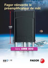
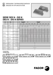
+LNBSPT 5213+LNB +LNB +LNB1 a 500 m(A) 1 a 500 m(A) 1 a 500 m(A)+LNBDEC 1 DEC 5IF IF 2 IF 3 IF 4 IF 5+LNB+LNBRFLEVELRF+LNBON/OFFMODE230 V~PROGLEVELAUTOMATICEQUALIZERAESCONTROLLEVEL12345678910AUTOMATICEQUALIZERAESCONTROL12345678910TVOUTPUTLEVEL1234567891080TV6253CHCHOUTPUTLEVEL123458 6 5 CH6789100OUTPUT+24 V20 mA2FMUHF 1UHF 2UHF 3VHF3CHOUTPUTFMUHF 1+24 V20 mAUHF 2UHF 3VHF■ EJEMPLO DE APLICACIÓN EXEMPLE D’APPLICATION ESEMPIO DI APPLICAZIONEANWENDUNGSBEISPIEL APPLICATION EXAMPLE EXEMPLO DO APLICAÇÃO■ UCF 100 Diagrama de programación Diagramme de programmation Diagrama di programmazioneProgrammierungsschema Programming diagram Diagrama de programaçãoMICROMATV Plus + PENTASAT 5FMUCF 100AUX. TVUHFMICROMATV1 9UHFSALIDAFMUHF1AB 012 FUHF2 FT 145 FUHF3UHF4UHFFT 130 FVHF❏ FAmpl. Nr.Reset+❏ M4 seg.+Gain-❏ ▲❏ ▼❏ F----❏ FA1 21 ❏▲ ❏ ▼AES❏ M4 seg.- - 21 ❏ F❏ M+Ch-❏ MAmpl. Nr.• INICIO Y RESET• START UND RESET• INITIALISATION ET RESET• START AND RESET• INIZIO E RESET• INÍCIO E RESET• ASIGNACIÓN DE CANALES• KANALZUTEILUNG• AFFECTATION DES CANAUX• CHANNEL ASSIGNATION• ALLOCAZIONE DEI CANALI• ASIGNAÇÃO DE CANAIS• ECUALIZACIÓN AUTOMÁTICA DE NIVELES• AUTOMATISCHE STABILISIERUNG DER LAUTSTÃRKE• EGALISATION AUTOMATIQUE DES NIVEAUX• AUTOMATIC LEVEL EQUALIZATION• EQUALIZZAZIONE AUTOMATICA DEI LIVELLI• EQUALIZAÇÃO AUTÓNOMA DE NÍVEIS• REGULACIÓN MANUAL DE NIVELES• MANUELLE REGULIERUNG DER LAUTSTÄRKE• EGALISATION MANUELLE DES NIVEAUX• MANUAL LEVEL SETTING• REGOLAZIONE MANUALE DEI LIVELLI• REGULAÇÃO MANUAL DE NÍVEISMICROMATV Plus + MICROMATV ■ Tab.1 Configuración de las entradas Configuration d’entrées Configurazione degli ingressiKonfiguration der eingänge Input configuration Configuração das entradasUHF UHF VHFFMUHFUHFUHFVHFMICROMATV<strong>plus</strong> 1.9 MICROMATV<strong>plus</strong> 2.8MICROMATV<strong>plus</strong> 5.5UHF2UHF1VHFUCF 100AUX. TVMICROMATV1 9SALIDAFMUHF1UHF2UHF3UHF4CHANNELS8 6 50 2 31 1 11 1 1INPUTSUHF1UHF2UHF3VHF1JUMPERSCHANNELS INPUTS6 4 3 UHF10 2 3 UHF22 2 2 UHF31 1 1 VHF11 1 1 VHF2JUMPERSCHANNELS5 4 30 1 24 3 20 1 2INPUTSUHF1UHF2JUMPERSVHF1VHF21 1 1 VHF3WARNING:WHEN YOU NEED TO CHANGE THE PLUG, THE WIRES OF THE MAINS SUPPLY FLEXIBLE CORDMUST NOT BE CONNECTED TO THE GROUND TERMINAL OF A THREE-PIN PLUG.JUMPERS6 7
GB■ DESCRIPTION● MICROMATV <strong>plus</strong>, is an amplification system capable ofindependently managing up to 10 television channels, aswell as FM signals.● Chanels are easily programmed using the UCF 100control unit which displays the amplifier number to beprogrammed and the selected channel.● The device may be reprogrammed as often as desired.The RESET function clears the memory of any existingprogrammes.● The device may receive signals from several antennas,allowing the system to be organised according to thenumber of channels received by each of them.● Designed for maximum versatility, it is easily expandableand easily incorporates any later changes or additions ofnew channels according to future needs.■ INSTALATION AND START-UPSetting up inputsPull out the jumpers and install them according to Table1 (page 7), as required by the number of channels to behandled by each of the inputs.■ PROGRAMMING CHANNELS● Connect the UCF 100 control unit (Ref 85100) to theprogramming connector (10). The display will show 4dashes “----“. See diagram UCF 100 on page 7.● Press the ❏F key to select the amplifier to beprogrammed. A display will show the amplifiernumber and the channel that is currently programmedfor example A1 27, A2 29....10 09.● Press the ❏ ▲ or ❏▼ keys to select the desired channelon each amplifier. The amplifiers without assignedchannels will display two dashes at the rightmost digits“--“ (disabled).● MICROMATV <strong>plus</strong> does not permit two amplifiers to beprogrammed to the same channel.● By pressing the ❏M (Memory), key all of the channelprogramme information will be stored. The display willshow four dashes indicating “operation with memoriseddata”.MICROMATV <strong>plus</strong> will automatically store theprogrammed information in memory three minutesafter the last key is pressed.System RESETBy pressing the ❏ M and ❏ F key simultaneously for fourseconds, the channel programmes will be cleared. Thedisplay will show two dashes “--“ in the righmostpositions next to each amplifier number(A1--, A2-- ...) indicating “amplifier disabled”.■ LEVELS ADJUSTMENT1.1. Automatic equalisation system : AES● Pressing the Automatic Equalisation System AES (11)button the MICROMATV <strong>plus</strong> will set the signal levels ofthe programmed amplifiers.● During this process the control unit keyboard will bedisabled, the display will flash the amplifier and channelwhich is in the process of adjustment, the AmplifierControl LEDs (9) will show the amplifier being adjustedand the Level Indicator (12) will display the signal inputlevel.● Once the automatic equalisation process has finished, theAmplifier Control LEDs (9) will be show the number ofany amplifier where an anomaly has been detected dueto anexcessively high or low input level. Automatic levelequalisaion will take a maximum of three minutes.1.2. Manual Level adjustment● Press the ❏M key for 4 seconds, the display will show thechannel assigned to each amplifier at the two rightmostdigits and the Amplifier Control LEDs (9) will indicate theamplifier being adjusted. The level indicator willalternately flash between red and yellow LEDs indicatingmanual adjustment.● Press the ❏F key to select the amplifier to be adjusted.● Press the ❏ ▲ or ❏▼ keys to adjust the gain of the amplifier selected.● With the General atenuator (5) set temporaly to maximumoutput, adjust the level of each channel, keeping track ofthe number of channels processed and the maximum output level according to Table 2.● The upper or lower adjustment limit will be indicated bythe horizontal segments of the control unit’s left display asboth upper or lower signals are lit respectively.2. Output level● Adjust the output level required by the installation usingthe General atenuator (5). Set the output level accordingto the number of amplified channels and the values inTable 2 to keep intermodulation (MI 3) at a level of-60 dBc.Tabla 2Number of channels 2 4 5 7 10Maximum output level dBµV 116 114 113 111 110(IM 3 -60 dB)RISK OF ELECTRIC SHOCK.DO NOT OPEN.■ DESCRIPZIONE● Il MICROMATV <strong>plus</strong>, è il sistema di amplificazione ingrado di gestire in modo indipendente fino a 10 canaliTV, oltre ai segnali di FM.● La programmazione dei canali si effettua facilmentemediante l’Unità di Controllo UCF 100 in cui possonoessere visualizzati il numero dell’amplificatore daprogrammare e il canale prescelto.● L’apparecchio può essere riprogrammato ogni voltache sia necessario. La funzione RESET cancella dallamemoria i programmi già esistenti.● L’apparecchio può ricevere segnali da varie antenne,permettendo di organizzare il sistema in funzione delnumero di canali captati da ciascuna di esse.● Progettato per offrire una grande versatilità, è facile daampliare ed è adatto a trattare eventuali cambiamenti oampliamenti di nuovi canali che possano essere effettuatiin futuro.■ INSTALAZIONE E AVVIOConfigurazione degli ingressiEstrarre i jumper e installarli come indicato nellaTabella 1 (pag. 7) in funzione del numero di canali datrattare per ciascuno degli ingressi.■ PROGRAMAZIONE DEI CANALI● Collegare l’Unità di Controllo UCF 100 (Rif. 85100) alconnettore di programmazione (10). Si visualizzano4 segmenti orizzontali sul display “----“.Vedi diagramma UCF 100 pag. 7.● Premere il tasto ❏F per selezionare l’amplificatore daprogrammare. Sul display appaiono il numerodell’amplificatore e il canale in cui è programmato, adesempio: A1 27, A2 29....10 09.● Premere il tasto ❏ ▲ o ❏▼ per impostare il canalerichiesto su ciascun amplificatore. Gli amplificatori senzacanale assegnato presenteranno due segmentiorizzontali sulle cifre a destra “--“ (disattivato).● MICROMATV <strong>plus</strong> non consente che due amplificatorisiano programmati sullo stesso canale.● Premendo il tasto ❏M (Memoria), si memorizzano i datidei canali programmati. Il display mostra 4 segmentiorizzontali “----“ che indicano: “Funzionamento condati memorizzati”.MICROMATV <strong>plus</strong> memorizza automaticamente i datiprogrammati una volta trascorsi 3 minuti dall’ultima voltain cui è stato premuto qualunque tasto.RESET del sistemaPremendo contemporaneamente per 4 secondi i tasti❏ M + ❏ F , si cancella la programmazione dei canali.Il display presenta quindi due segmenti orizzontali sullecifre a destra “--“a lato di ciascun amplificatore(A1--, A2-- ...) che indicano: “Amplificatoredisattivato”.■ REGOLAZIONE DEI LIVELLI1.1. Equalizzazione automatica dei livelli: AES● Premendo il pulsante del sistema di equalizzazioneautomatica dei livelli: AES (11) il MICROMATV <strong>plus</strong>uguaglierà il livello dei segnali degli amplificatoriprogrammati.● Nel corso di questo processo la tastiera dell’Unità diControllo UCF 100 è disabilitato: il display mostra con unlampeggiamento l’amplificatore e il canale su cui si staeffettuando la regolazione; i LED del controlloamplificatori (9) mostrano l’amplificatore in fase diregolazione e l’indicatore di livello (12) presental’intensità del segnale in ingresso.● Alla conclusione del processo di equalizzazioneautomatica si accendono i LED del controllo amplificatori(9) con il numero di amplificatore in cui sia statariscontrata un’anomalia per eccesso o per difetto dilivello in ingresso.La durata dell’equalizzazione automatica dei livelli è di3 minuti al massimo.1.2. Regolazione manuale dei livelli● Premere il tasto ❏M per 4 secondi, il display mostra,sulle cifre a destra, il canale assegnato a ciascunamplificatore e i LED di controllo amplificatori (9)indicano l’amplificatore in fase di regolazione.L’indicatore di livello presenta i led rosso e giallo inlampeggiamento alternato per indicare la “Regolazionemanuale”.● Premere il tasto ❏F per impostare l’amplificatore daregolare.● Premere i tasti ❏ ▲ o ❏▼ per regolare il guadagnodell’amplificatore richiesto.● Mediante l’attenuatore generale (6) provvisoriamentesulla massima uscita, regolare il livello di ciascun canaletenendo conto del numero di canali processati e il livellomassimo di uscita secondo la Tabella 2.● Il limite della regolazione superiore o inferiore è indicatodai segmenti orizzontali dei display a sinistra dell’unità dicontrollo quando si accendono rispettivamente entrambi isegmenti superiori o inferiori.2. Livello di uscita● Regolare il livello di uscita su quello richiestodall’impianto mediante l’attenuatore generale (6).Regolare tenendo conto del numero dei canali amplificatie i valori della Tabella 2 per mantenerel’intermodulazione (IM 3) ad un livello di -60 dBc.Tabella 2N. di canali 2 4 5 7 10Livello massimouscitadBµV 116 114 113 111 110(IM 3 -60 dBc)RISCHIO DI SCARICA ELETTRICA.NON APRIRE.I89
P■ DESCRIÇÃO● O MICROMATV <strong>plus</strong>, é um Sistema de Amplificaçãocapaz de governar de forma independente até 10canais de TV, além dos sinais de FM.● A programação dos canais se faz com facilidade através da Unidade de Controlo UCF 100, na qualaparece visível o número do amplificador que vai serprogramado, bem como o canal seleccionado.● O aparelho pode-se tornar a programar todas asvezes que se desejar. A função RESET fazdesaparecer da memória os programas existentes namesma.● O aparelho pode receber sinais através de váriasantenas, sendo possível organizar o sistema deacordo com o número de canais recebidos em cadauma delas.● Desenhado de modo que possui uma grãversatilidade, é facilmente ampliável e adequadopara tratar possíveis modificaçoes ou fazerampliações com outros canais novos que possamaparecer no futuro.■ INSTALAÇÃO E FUNCIONAMENTOConfiguração das entradasExtrair os Jumper e instalâ-los na tabela I (p·g. 7), deacordo com o n˙mero de canais que vão ser tratadosem cada uma das entradas.■ PROGRAMAÇÃO DOS CANAIS● Fazer a ligação da Unidade de Controlo UCF 100(Ref. 85100) no conector de programação (10).Nesse momento aparecem no display 4 traçoshorizontais “----“. Ver diagrama UCF 100 pág. 7.● Fazer pressão no botão ❏F para seleccionar oamplificador que se desejar programar. Apareceentão no display o número do amplificador e o canalno qual está programado; por ex.:A1 27, A2 29....10 09.Fazer pressão nos botões ❏ ▲ ou ❏●▼ para seleccionaro canal desejado para cada amplificador. Osamplificadores que não têm canal designado apresentam dois traços horizontais nos digitos da direita“--“ (não activado).● MICROMATV <strong>plus</strong> não permite que doisamplificadores sejam programados no mesmo canal.● Fazendo pressão no botão ❏ M (memória)memorizam-se os dados dos canais programados.Nesse momento aparecem no display 4 traçoshorizontais “----“ com a indicação: “funcionamentocom dados memorizados”.O MICROMATV <strong>plus</strong> memoriza automaticamente osdadosprogramados 3 minutos depois de ter tocado oúltimo botão.RESET do sistemaFazendo pressão ao mesmo tempo durante 4 segundos nos botões ❏ M + ❏ F desaparece a programaçãodos canais. Ao mesmo tempo aparecem no displaydois traços horizontais nos dígitos da direita “--“ aolado de cada um dos amplificadores (R1--, R2-- ...)com a indicação: “amplificador não activado”.■ REGULAÇÃO DE NÍVEIS1.1. Equalização Automática de níveis: AES● Fazendo pressão sobre o botão do sistema deEqualização Automática de níveis AES (11), oMICROMATV <strong>plus</strong> iguala o nível dos sinais dosamplifcadores programados.● Durante este processo os botões da Unidade deControlo UCF 100 ficam inabilitados: nesse momento,o display apresenta com um pisca-pisca oamplificador e o canal no qual está a se fazer aregulação; os LED do Controlo de Amplificadores (9)apresentam o amplificador que está a ser regulado, eo Indicador de Nível (12) apresenta a intensidade dosinal de entrada.● Ao finalizar o processo de equalização automática iluminam-se os LED do Controlo de Amplificadores (9)com o Nº de amplificador no qual foi detectadaalguma anomalia por defeito ou por excesso no nívelde entrada.A equalização automática de níveis pode ter umaduração máxima de 3 minutos.1.2. Regulação manual de níveis● Fazer pressão na tecla ❏M durante 4 segundos.Nesse momento o display apresenta nos dígitos dadireita o canal designado para cada amplificador,enquanto os LED do Controlo de Amplificadores (9)indicam o amplificador que está a ser regulado.O indicador de nível apresenta fazendo pisca-pisca osLED vermelhos e amarelos, com a indicação“regulação manual”.● Fazer pressão no botão ❏F para seleccionar oamplificador que se deseja regular.● Fazer pressão nos botões ❏ ▲ ou ❏▼ para regular oganho do amplificador desejado.● Com o Atenuador Geral (5), provisoriamente amáxima saída, regular o nível de cada canal tendo emconta o número de canais processados e o nívelmáximo de saída segundo a Tabela 2.● O limite da regulação superior ou inferior vemindicado pelos traços horizontais dos display do ladoesquerdo da Unidade de Controlo ao iluminar-se ostraços superiores e inferiores respectivamente.2. Nível de saída.● Regular o nível de saída adaptando-o ao requeridopela instalação por meio do Atenuador Geral (5).Regular o nível de saída tendo em conta o número decanais amplificados e os valores da Tabela 2 paramanter a intermodulação (IM 3) no nível de 60 dBc.Tabela 2Nº de canais 2 4 5 7 10Nivel máx. saída dBµV 116 114 113 111 110(IM 3 -60 dBc)RISCO DE SHOCK ELÉCTRICO.NÃO ABRIR.Tab. 4Ref. 35445; Ref. 35465; Ref. 35485FREQUENCIESDISPLAY BAND CHANNEL VIDEO FREC. (MHz)02 VHF E2 48.2503 E3 55.2504 E4 62.25L2 L2 55.75L3 L3 60.55L4 L4 63.75-0 A 53.75-1 B 62.2505 E5 175.2506 E6 182.2507 E7 189.2508 E8 196.2509 E9 203.2510 E10 210.2511 E11 217.2512 E12 224.25A L5 L5 176.00A L6 L6 184.00A L7 L7 192.00A L8 L8 200.00A L9 L9 208.00A L0 L10 216.0021 UHF 21 471.2522 22 479.2523 23 487.2524 24 495.2525 25 503.2526 26 511.2527 27 519.2528 28 527.2529 29 535.2530 30 543.2531 31 551.2532 32 559.2533 33 567.25DISPLAY BAND CHANNEL VIDEO FREC. (MHz)34 UHF 34 575.2535 35 583.2536 36 591.2537 37 599.2538 38 607.2539 39 615.2540 40 623.2541 41 631.2542 42 639.2543 43 647.2544 44 655.2545 45 663.2546 46 671.2547 47 679.2548 48 687.2549 49 695.2550 50 703.2551 51 711.2552 52 719.2553 53 727.2554 54 735.2555 55 743.2556 56 751.2557 57 759.2558 58 767.2559 59 775.2560 60 783.2561 61 791.2562 62 799.2563 63 807.2564 64 815.2565 65 823.2566 66 831.2567 67 839.2568 68 847.2569 69 855.251011