E I NL F GB D - MVG
E I NL F GB D - MVG E I NL F GB D - MVG
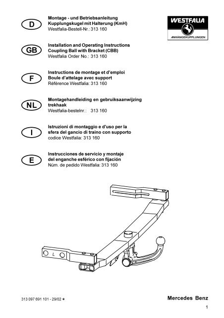
- Page 2 and 3: DMontage - und BetriebsanleitungKup
- Page 4 and 5: Montageanleitung:1.) Kofferraumabde
- Page 6 and 7: 6Mindestabstandvon Kfz. Teilen
- Page 9 and 10: Bedienungsanleitung für abnehmbare
- Page 11 and 12: Abnehmbare Kugelstange (Automatic)D
- Page 13 and 14: The ball and coupling must be kept
- Page 15 and 16: GBAvailable Spare Parts for Couplin
- Page 17: D - Der Freiraum nach Anhang VII, A
- Page 20 and 21: GBB. UNMOUNTING1. Remove cover cap
- Page 22 and 23: FInstructions de montage et d’emp
- Page 24 and 25: Instructions de montage:1.) Dépose
- Page 26 and 27: 26Distance à respecterdes pièces
- Page 29 and 30: Notice d ' utilisation de l ' attel
- Page 31 and 32: Barre à boule amovible ( automatis
- Page 33 and 34: NLDe kogel resp. koppeling moet sch
- Page 35 and 36: Leverbare vervangingsonderdelen van
- Page 37: D - Der Freiraum nach Anhang VII, A
- Page 40 and 41: NLB. DEMONTAGE1. Het afsluitdopje v
- Page 42 and 43: IIstruzioni di montaggio e d'uso pe
- Page 44 and 45: Istruzioni di montaggio :1.) Smonta
- Page 46 and 47: 46Distanza minima dalleparti del ve
- Page 49 and 50: Istruzioni per l'uso della sfera de
- Page 51 and 52: Barra sferica amovibile (Automatic)
DMontage - und BetriebsanleitungKupplungskugel mit HalterungWestfalia-Bestell-Nr. : 313 160Typ: 313 097EG-Genehmigungszeichen: e13 00-0024Verwendungsbereich: Mercedes Benz,E-Klasse, W 210 (Limousine ab Juni 1995)nicht für AMG FahrzeugeAmtliche Typenbezeichnungnach EG-Typgenehmigung: 210, J 0Achtung: Bei Motorisierung 300er Turbodiesel (Motor 606) in Verbindung mit Klimaanlage bzw.-automatik muß für den Anhängerbetrieb ein Getriebeölkühler mit Gebläsemotor,sowie ein Gebläse für den Motorölkühler nachgerüstet werden.Ist zusätzlich eine Standheizung vorhanden, muß diese demontiert werden, da sie denBauraum der oben genannten Bauteile belegt.Technische Daten:Der geprüfte D - Wert beträgt 10,8 kN. Dieser entspricht zum Beispiel einer Anhängelast von 2000kg und einem zulässigen Gesamtgewicht von 2400 kg. Die geprüfte Stützlast beträgt75 kg.Für den Fahrbetrieb sind die Angaben des Fahrzeugherstellers bzgl. Anhängelast und Stützlastmaßgebend, wobei die geprüften Werte der Anhängevorrichtung nicht überschritten werdendürfen.Hinweise:Die Anhängevorrichtung ist ein Sicherheitsteil und darf nur von Fachpersonal montiert werden.Sofern Ersatzteile erforderlich werden, dürfen auch diese nur von Fachpersonal amunbeschädigten Originalteil verbaut werden.Jegliche Änderungen bzw. Umbauten an der Anhängevorrichtung sind unzulässig. Sie führenüberdies zum Erlöschen der Betriebserlaubnis.Bei Fahrt mit Anhänger sind die Fahrthinweise in der Betriebsanleitung des Fahrzeugherstellerszu beachten.Die Anhänger müssen mit einer entsprechenden Zugkugelkupplung ausgerüstet sein.Muß durch den Anbau der Anhängevorrichtung die Abschleppöse entfernt werden, dient diese alsErsatz hierfür, sofern die zulässige Anhängelast nicht überschritten wird und derAbschleppvorgang auf verkehrsüblichen Straßen erfolgt.2
Die Kugel bzw. Kupplung ist sauber zu halten und zu fetten.Achtung : Bei Benutzung von Spurstabilisierungseinrichtungen, wie z.B. der Westfalia "SSK"muß die Kupplungskugel fettfrei sein.Die Hinweise in der Bedienungsanleitung beachten!Der Durchmesser der Kugel ist von Zeit zu Zeit zu überprüfen.Sobald an einer beliebigen Stelle eine Verschleißgrenze von 49,0 mm erreicht ist, darf dieAnhängevorrichtung aus Sicherheitsgründen nicht mehr benutzt werden.Die vom Fahrzeughersteller serienmäßig genehmigten Befestigungspunkte sind eingehalten.Nationale Richtlinien über die Anbauabnahmen sind zu beachten.Diese Montage- und Betriebsanleitung ist den Kfz. - Papieren beizufügen.DAllgemeine Montagehinweise :Die zu verwendenden mikroverkapselten Sechskantschrauben dürfen nur einmal verwendetwerden. Werden Teile der Anhängevorrichtung gelöst, so sind beim Wiedereinbau neuemikroverkapselte Sechskantschrauben zu verwenden.An den Karosserieauflagestellen der KmH ist das Karosseriedichtmittel und der Unterbodenschutzmit einem Spachtel zu entfernen. Flächen anschließend mit Waschbenzin säubern. BlankeKarosseriestellen mit Rostschutzfarbe nachstreichen. Bohrungen (für Montage der KmH) entgraten.Bohrspäne entfernen.Elektrische Anlage 7 - polig gemäß DINV 72570 montieren.Elektrische Anlage 13 - polig gemäß ISO 11446 montieren.Schild mit Stützlastangabe an das Kfz. in Nähe der Anhängevorrichtung oder an die Innenseite desKofferraums an gut sichtbarer Stelle anbringen.Sämtliche Befestigungsschrauben der Anhängevorrichtung nach ca. 1000 Anhänger - kmnachziehen.Diese Anhängevorrichtung einschließlich aller Montageteile wiegt 19,9 kg. Bitte berücksichtigenSie, daß sich das Leergewicht Ihres Kfz. nach Montage der Anhängevorrichtung um diesen Betragerhöht.3
Montageanleitung:1.) Kofferraumabdeckung, Reserverad, Verkleidung-Heckmittelstück, Seitenverkleidung linksund rechts im Kofferraum, hinterem Stoßfänger, Haupt- und Nachschalldämpfer (abVerschraubung) und Abschirmblech des Nachschalldämpfers ausbauen.Wagenheber herausnehmen.2.) Den Bohrpunkt 5 -Körnermakrierung - am linken Fahrzeuglängsträger vorbohren und auf Ø15ausarbeiten. Drei Bohrungen bei "b" (1x links und 2x rechts) sind vorhanden.(Gummistopfen- rechte Seite- entfernen)3.) Die Bohrpunkte 2 und 4 (4x ) - Körnermarkierung - entsprechend Position "a" der KmH 13 imFahrzeugheckquerträger vorbohren und auf Ø18mm ausarbeiten (Maß 1050 mm beachten).4.) Die Bohrpunkte 7 - Körnermarkierung - im Fahrzeugabschlußblech rechts und links aufØ 70 mm ausarbeiten (z. B. mit Lochsäge).5.) Bohrung für Zapfen 1 im Fahrzeug - Heckquerträger ankörnen und Ø 54 mm ausarbeiten (z.B.mit Lochsäge). Hierzu Fahrzeugmitte ausmessen und Maß 47 mm beachten (siehe Skizze"Schnitt Mitte Fahrzeug").6.) Versteifungsträger 2 (links bzw. rechts beachten) von hinten durch die Bohrungen Ø 70 mm inden linken bzw. rechten Fahrzeuglängsträger einsetzen.7.) Gegenlaschen 10 - links von der Fahrzeugunterseite und rechts von der Kofferrauminnenseite- bei "b" einsetzen und mit Sicherungsmuttern M10 lose verschrauben.8.) KmH 13 unter das Fahrzeug halten und bei "a" mit Sechskantschrauben M12x1,5x70 loseverschrauben. Vorher Dichtungen 3 (2x) auf Zapfen 1 aufschieben.9.) KmH (kpl.) ausrichten. Sechskantschrauben/Sechskantmuttern festziehen.4DAnzugsdrehmomente: Sechskantschrauben M12 95 Nm (bei "a")Sechskantmuttern M10 40 Nm (bei "b")Es werden Sechskantschrauben der Festigkeitsklasse 10.9 und Schweißschrauben/Sechskantmuttern der Festigkeitsklasse 8.8 bzw. 8 verwendet.10.) Verschlußstopfen 15 in die Bohrungen Ø 70 mm in das Fahrzeugabschlußblech einsetzen.11.) Kofferraum reinigen und ausgebaute/herausgenommene Teile einbauen bzw. hineinlegen.12.) Schild mit Stützlastangabe auf die Ladekante oder Innenseite des Kofferraumes kleben (s.Position 16).13.) Bei Fahrt ohne Anhänger:Kugelstange abnehmen, in gelieferte Tasche verpacken und sicher gegen verrutschen imKofferraum verstauen. Stopfen in das Aufnahmerohr einsetzen.Änderungen vorbehalten.
DLieferbare Ersatzteilumfänge der Kupplungskugel mit HalterungErsatzteil-Nr.Bezeichnung913 097 650 001 Befestigungsteile913 097 601 001 Kugelstange905 051 630 106 Verschlußstopfen (für Aufnahmerohr)913 097 650 002 Stützen5
6Mindestabstandvon Kfz. Teilen
D - Der Freiraum nach Anhang VII, Abbildung 30 der Richtlinie 94/20/EG ist zu gewährleisten.DK - Frirummet skal overholdes iht. bilag VII, fig. 30 i direktiv 94/20/EF.CZ - Volný prostor ve smyslu Pøílohy VII, obr. 30 Smìrnice è. 94/20/EG musí být zaruèen.E - Debe garantizarse el espacio libre, conforme al anexo VII, figura 30 de la directiva comunitaria CE/94/20.F - La zone de dégagement doit être garantie conformément à l'annexe VII, illustration 30 de la directive 94/20/CE.FIN - Vapaa tila on taattava direktiivin 94/20/EY liitteen VII, kuvan 30 mukaisesti.<strong>GB</strong> - The clearance specified in appendix VII, diagram 30 of guideline 94/20/EG must be guaranteed.GR - ÐñÝðåé íá åîáóöáëßæåôáé ï åëåýèåñïò ÷þñïò óýìöùíá ìå ôï ðáñÜñôçìá VII, åéêüíá 30 ôçò Ïäçãßáò 94/20/EÏÊ.H - Biztosítani kell a 94/20/EK irányelv szerinti, VII. számú függelék 30. ábrában jelölt szabad teret.I - Deve essere garantito lo spazio libero secondo l'allegato VII, figura 30 della direttiva 94/20/CE.N - Frirommet etter tillegg VII, avbilding 30 i direktiv 94/20/EEC skal overholdes.<strong>NL</strong> - De tussenruimte conform supplement VII, afbeelding 30 van de richtlijn 94/20/EG moet in acht wordengenomen.P - Garantir a zona livre, conforme Anexo VII, gráfico 30 da Norma 94/20/CE.PL - Nale¿y zagwarantowaæ przestrzeñ swobodn¹ wed³ug za³¹cznika VII, ilustracja 30 wytycznej 94/20/EG .S - Spelrummet enligt bilaga VII, figur 30 i riktlinje 94/20/EG skall garanteras.SLO - Zagotoviti zraènost po priklopu VII, slika 30, smernice 94/20/EG .SK - Volný priestor v zmysle Prílohy VII, obr. 30 Smernice è. 94/20/EG musí by zaruèený.TR - 94/20/EG Yönetmeliði, Ek VII, Resim 30'da belirtilen serbest alan býrakýlmalýdýr.D - bei zulässigem Gesamtgewicht des FahrzeugesDK - ved tilladt samlet vægt for køretøjetCZ - pøi celkové pøípustné hmotnosti vozidlaE - con peso total autorizado del vehículoF - pour poids total en charge autorisé du véhiculeFIN - ajoneuvon suurimmalla sallitulla kokonaispainolla<strong>GB</strong> - at laden weight of the vehicleGR - ãéá ôï åðéôñåðôü ìéêôü âÜñïò ôïõ ï÷ÞìáôïòH - a jármû megengedett össztömege eseténI - per un peso complessivo ammesso del veicoloN - ved kjøretøyets tillatte totalvekt<strong>NL</strong> - bij toelaatbaar totaal gewicht van het voertuigP - com o peso total permitido do veículoPL - przy dopuszczalnym ciê¿arze ca³kowitym pojazduS - vid fordonets tillåtna totalviktSLO - pri dovoljeni skupni teži vozilaSK - pri celkovej prípustnej hmotnosti vozidlaTR - Taþýtýn azami toplam aðýrlýðýnda7
Bedienungsanleitung für abnehmbare KugelstangeACHTUNG:• Vor jeder Fahrt mit dem Anhänger die Kugelstange auf ordnungsgemäßeVerriegelung überprüfen (siehe unter A. 3)!• Nie bei angekuppeltem Anhänger entriegeln!• Bei Fahrt ohne Anhänger und durch die Kugel im Sichtbereich eingeschränktemamtlichen Kennzeichen muß die Kugelstange abgenommen und immer derVerschlußstopfen in das Aufnahmerohr eingesetzt werden!Ansonsten sollte auch bei nicht verdecktem Kennzeichen die Kugelstangeabgenommen werden.A. MONTAGE1. Verschlußstopfen aus dem Aufnahmerohr herausziehen.Im Normalfall befindet sich die Kugelstange, wenn sie aus dem Kofferraum entnommen wird,im "vorgespannten Zustand". Dieser ist daran erkennbar, daß der Auslösehebel (s. Skizze) ander Kugelstange anliegt, das Handrad ca. 6 mm von der Kugelstange absteht (s. Skizze) und die" Rot - Markierung " des Handrades in dem "Grün - Bereich" der Kugelstange liegt.Berücksichtigen Sie, daß die Kugelstange nur in diesem Zustand eingesetzt werdenkann!Sollte der Verriegelungsmechanismus der Kugelstange vor Montage, wodurch auch immer,ausgelöst worden sein - Sie erkennen dieses daran, daß der Auslösehebel (s. Skizze) ca. 5mm von der Kugelstange absteht, die "Grün - Markierung" des Handrades mit dem "Grün-Bereich"der Kugelstange übereinstimmt und das Handrad (s. Skizze) an der Kugelstange anliegt - so mußder Verriegelungsmechanismus wie folgt vorgespannt werden:Bei eingestecktem Schlüssel und geöffnetem Schloß das Handrad seitlich herausziehen undin Pfeilrichtung bis zum Anschlag drehen. Der Auslösehebel rastet sodann ein, und nachLoslassen des Handrades verbleibt der Verriegelungsmechanismus in der vorgespanntenStellung.2. Zur Montage der Kugelstange diese von unten in das Aufnahmerohr einsetzen undhochdrücken.Der Verriegelungsvorgang wird hierdurch automatisch durchgeführt.Hand nicht im Bereich des Handrades halten.Schloß schließen und Schlüssel abziehen.Abdeckkappe vom Schlüssel abziehen und auf das Schloß drücken!3. Aus Sicherheitsgründen:Kontrollieren Sie immer, ob die Kugelstange vorschriftsmäßig verriegelt und gesichert ist.Dies erkennen Sie an folgenden Merkmalen:• Markierung "Grün" des Handrades stimmt mit "Grün" - Bereich an Kugelstange überein.• Handrad liegt an Kugelstange an (kein Spalt)• Schloß verschlossen und Schlüssel abgezogen (Handrad läßt sich nicht herausziehen)• Kugelstange muß völlig fest im Aufnahmerohr sitzen (durch Rütteln von Hand prüfen)Falls die Prüfung aller 4 Merkmale nicht zufriedenstellend ausfällt, ist die Montage zuwiederholen.Sofern auch dann nur eines der Merkmale nicht erfüllt wird, darf die Anhängevorrichtung nichtbenutzt werden.Setzen Sie sich mit dem Hersteller in Verbindung.D9
DB. DEMONTAGE1. Abdeckkappe vom Schloß abziehen und Abdeckkappe auf den Griff des Schlüssels drücken.Schloß mit Schlüssel öffnen (Schlüssel läßt sich bei geöffnetem Schloß nicht abziehen!)2. Kugelstange festhalten, Handrad seitlich herausziehen und entgegen der Federkraft inPfeilrichtung bis zum Anschlag drehen.Kugelstange nach unten aus dem Aufnahmerohr herausnehmen.Das Handrad kann sodann losgelassen werden, es arretiert selbsttätig in der gespanntenStellung.Beachten Sie hierzu auch die Symbole auf dem Handrad sowie die beiliegende Skizze"Abnehmbare Kugelstange".3. Kugelstange im Kofferraum sicher und gegen Verschmutzen geschützt verstauen.Wie bereits erwähnt, kann der Schlüssel in der gespannten Stellung nicht abgezogen werden.Verschlußstopfen in das Aufnahmerohr einsetzen !C. BITTE UNBEDINGT BEACHTEN !Die Montage und Demontage der Kugelstange ist mit normaler Handkraft problemlosauszuführen.Benutzen Sie niemals irgendwelche Hilfsmittel, Werkzeuge usw., da hierdurch derMechanismus beschädigt werden könnte.Reparaturen und Zerlegung der abnehmbaren Kugelstange dürfen grundsätzlich nur von uns alsHersteller durchgeführt werden.An der gesamten Anhängevorrichtung dürften keine Veränderungen vorgenommen werden.Schlüsselnummer für eventuelle spätere Nachbestellung notieren.Beiliegendes Hinweisschild am Kfz. in der Nähe des Aufnahmerohres oder an der Innenseitedes Kofferraumes an gut sichtbarer Stelle anbringen.D. WARTUNGSHINWEISE1. Um eine ordnungsgemäße Funktion zu gewährleisten, müssen die Kugelstange und dasAufnahmerohr stets sauber sein.2. Auf regelmäßige Pflege der Mechanik ist zu achten.Lagerstellen, Gleitflächen und Kugeln mit harzfreiem Fett bzw. Öl regelmäßig fetten bzw. ölen.Schloß nur mit harz- und säurefreiem Öl behandeln.3. Wird die abnehmbare Kugelstange über einen längeren Zeitraum nicht benutzt, sollte zurEntlastung der Federelemente der Verriegelungsmechanismus stets entspannt (verriegelteStellung) sein.Zum Entspannen Auslösehebel nach vorn drücken.4. Bei Reinigung des Fahrzeuges mit einem Dampfstrahler muß die Kugelstangeabgenommen und der Verschlußstopfen eingesetzt werden.(Kugelstange darf nicht dampfgestrahlt werden)10
Abnehmbare Kugelstange (Automatic)DVerriegelte Stellung (Fahrbetrieb)Kugeln (herausgedrückt)Aufnahmerohr (Halterung)Markierung grünSymbol (Betätigung entriegeln)GleitflächeAuslösehebelHandrad kommt amBolzen zur Anlage (keinSpalt)Abdeckkappe (für Schloß)Markierung rotSchlüssel abgenommen(ohne Abdecklappe fürSchloß)Handrad (Stellung verriegelt)Entriegelte Stellung (abgenommen)Kugeln (Lage innerhalbder Bohrung)Nut (für Zapfen und Handrad)Spalt Handrad-Bolzen ca. 6 mmBolzenKeilflächen (Gleitflächen)(Handrad herausziehen)(Handrad drehen)Markierung rotSchlüssel mit Abdeckkappefür Schloß(Schlüssel nicht abziehbar!)11
<strong>GB</strong>Installation and Operating InstructionsCoupling Ball with Bracket (CBB)Westfalia Order No.: 313 160Type: 313 097EC Auth. Des.: e13 00-0024Application: Mercedes-Benz E Class W 210 (saloon/sedan as of June 1995);not for AMG vehiclesEC Authorised Designation: 210, J 0Attention:If the vehicle to which the towing device is to be fitted is a 300 Turbodiesel model(engine 606) equipped with air-conditioning or automatic air-conditioning system, atransmission oil cooler with fan motor and a fan for the engine oil cooler must bothbe retrofitted.If the vehicle is also equipped with a parking/auxiliary heater, this heater must beremoved because it is located in the space where the components mentioned abovehave to be installed.Technical Data:The tested D-value is 10,8 kN. This corresponds, for example, to a towed weight of 2000 kg anda permissible total weight of 2400 kg. The tested trailer nose weight is 75 kg. For driving, the dataof the vehicle manufacturer with regard to the towed weight and trailer nose weight are decisive,whereby the tested values of the CBB may not be exceeded.Notes:The CBB is a safety part and may only be mounted by specially trained personnel. Should spareparts be required, these may also only be mounted on the undamaged original-equipment part byspecially trained personnel.No changes or modifications to the CBB are permitted.When driving with a trailer, observe the driving instructions in the vehicle manufacturer's operatinginstructions.The trailer must be equipped with an appropriate towing coupling ball.If installing the CBB necessitates the removal of the towing eye, the CBB serves as a replacement,provided the permissible towed weight is not exceeded and the towing takes place on normalroads.12
The ball and coupling must be kept clean and greased.Important: When using track stabilising devices, e.g. the Westfalia "SSK", the coupling ballmust be grease-free.Follow the instructions in the operating instructions.Check the ball diameter from time to time.As soon as a diameter of 49.0 mm is reached at any given point, the CBB may no longer be usedfor safety reasons.The fixing points specified as standard must be observed.National guidelines concerning official approval of auxiliaries must be observed.These installation and operating instructions must be enclosed with the vehicle papers.<strong>GB</strong>General Installation Instructions:The micro-encapsulated hexagon bolts that must to be used are only allowed to be used once. If partsof the towing device are loosened or removed, always use new micro-encapsulated hexagon boltswhen refitting them.Using a filling knife, remove the insulating compound and underseal from the area of the bodyworkat which the CBB will make contact with the body. Then clean the surfaces with naphtha. Coat thebare bodywork with anti-corrosion paint. Deburr the holes (for mounting the CBB) and remove allchips.Mount 7-pin electrical system as per DINV 72570.Mount 13-pin electrical system as per ISO 11446.Apply the trailer nose-weight plate to the vehicle near the CBB or in the luggage boot in an easy-toseelocationRetighten all mounting bolts of the CBB after approx. 1,000 towing km.This CBB including all mounting parts weighs 19,9 kg. Please take into account that the curb weightof your vehicle is increased by this amount after mounting the CBB.13
<strong>GB</strong>Installation Instructions:1.) Remove the luggage compartment cover, spare wheel, the trim from the centre section of therear panel, the left and right side panels in the luggage compartment, the rear bumper, the mainand rear silencers (from the bolted joint) and the shield of the rear bumper. Remove the jack.2.) Predrill drilling point "5" – marked by a prick-punch – on the left-hand frame side member andthen drill it out to Ø 15 mm. Three holes are already present at position "b" (1 left and 2 right).3.) Predrill drilling points "2" and "4" (there are 4 of them) – marked by a prick-punch – in line withposition "a" of CBB "13" in the cross member at the rear end of the vehicle and then drill themout to Ø 18 mm (observe the dimension of 1050 mm).4.) Enlarge drilling points "7" – marked by a prick-punch – on the right- and left-hand sides of therear apron to Ø 70 mm using e.g. a hole saw.5.) Using a centre punch, mark the position of the hole for stub "1" in the cross member at the rearend and enlarge the hole to Ø 54 mm using e.g. a hole saw. To do this, measure up the centreof the vehicle and observe the dimension of 47 mm (see sketch "Cutout in centre of vehicle").6.) Insert reinforcements "2" (do not mix up reinforcements for left and right) into the left and rightframe side members through the Ø 70 mm holes.7.) Insert fishplates "10" – on the left from beneath the vehicle and on the right from inside theluggage compartment – at positions "b" and bolt loosely using M 10 locknuts.8.) Push seals "3" (there are 2) onto stub "1". Hold CBB "13" under the vehicle and bolt it looselyto the vehicle at positions "a" using M 12 x 1.5 x 70 hexagon bolts.9.) Align the complete CBB and tighten the hexagon nuts and bolts.Tightening torques: hexagon bolts M 12 95 Nm (at "a")hexagon nuts M 10 40 Nm (at "b")The hexagon bolts used are of strength class 10.9 and the weldbolts/hexagon nuts of strengthclass 8.8 and 8 respectively.10.) Push plugs "15" into the Ø 70 mm holes in the rear apron.11.) Clean the luggage compartment and refit/replace all the parts (trim panels, jack etc.) removed.12.) Affix the trailer nose-weight plate to the luggage compartment sill or inside of the luggagecompartment (see item 16).13.) When not towing a trailer:always remove the towbar, pack it in the bag supplied and stow it in the luggage compartmentin such a way that it cannot slide around and cause damage. Insert the sealing plug into themounting pipe.Subject to change.14
<strong>GB</strong>Available Spare Parts for Coupling Ball with BracketSpare Part No.Description913 097 650 001 Pack. Fixtures913 097 601 001 Pack. Towbar905 051 630 106 Pack. Sealing plug (for mounting pipe)913 097 650 002 Support15
16Minimum clearancefrom vehicle parts
D - Der Freiraum nach Anhang VII, Abbildung 30 der Richtlinie 94/20/EG ist zu gewährleisten.DK - Frirummet skal overholdes iht. bilag VII, fig. 30 i direktiv 94/20/EF.CZ - Volný prostor ve smyslu Pøílohy VII, obr. 30 Smìrnice è. 94/20/EG musí být zaruèen.E - Debe garantizarse el espacio libre, conforme al anexo VII, figura 30 de la directiva comunitaria CE/94/20.F - La zone de dégagement doit être garantie conformément à l'annexe VII, illustration 30 de la directive 94/20/CE.FIN - Vapaa tila on taattava direktiivin 94/20/EY liitteen VII, kuvan 30 mukaisesti.<strong>GB</strong> - The clearance specified in appendix VII, diagram 30 of guideline 94/20/EG must be guaranteed.GR - ÐñÝðåé íá åîáóöáëßæåôáé ï åëåýèåñïò ÷þñïò óýìöùíá ìå ôï ðáñÜñôçìá VII, åéêüíá 30 ôçò Ïäçãßáò 94/20/EÏÊ.H - Biztosítani kell a 94/20/EK irányelv szerinti, VII. számú függelék 30. ábrában jelölt szabad teret.I - Deve essere garantito lo spazio libero secondo l'allegato VII, figura 30 della direttiva 94/20/CE.N - Frirommet etter tillegg VII, avbilding 30 i direktiv 94/20/EEC skal overholdes.<strong>NL</strong> - De tussenruimte conform supplement VII, afbeelding 30 van de richtlijn 94/20/EG moet in acht wordengenomen.P - Garantir a zona livre, conforme Anexo VII, gráfico 30 da Norma 94/20/CE.PL - Nale¿y zagwarantowaæ przestrzeñ swobodn¹ wed³ug za³¹cznika VII, ilustracja 30 wytycznej 94/20/EG .S - Spelrummet enligt bilaga VII, figur 30 i riktlinje 94/20/EG skall garanteras.SLO - Zagotoviti zraènost po priklopu VII, slika 30, smernice 94/20/EG .SK - Volný priestor v zmysle Prílohy VII, obr. 30 Smernice è. 94/20/EG musí by zaruèený.TR - 94/20/EG Yönetmeliði, Ek VII, Resim 30'da belirtilen serbest alan býrakýlmalýdýr.D - bei zulässigem Gesamtgewicht des FahrzeugesDK - ved tilladt samlet vægt for køretøjetCZ - pøi celkové pøípustné hmotnosti vozidlaE - con peso total autorizado del vehículoF - pour poids total en charge autorisé du véhiculeFIN - ajoneuvon suurimmalla sallitulla kokonaispainolla<strong>GB</strong> - at laden weight of the vehicleGR - ãéá ôï åðéôñåðôü ìéêôü âÜñïò ôïõ ï÷ÞìáôïòH - a jármû megengedett össztömege eseténI - per un peso complessivo ammesso del veicoloN - ved kjøretøyets tillatte totalvekt<strong>NL</strong> - bij toelaatbaar totaal gewicht van het voertuigP - com o peso total permitido do veículoPL - przy dopuszczalnym ciê¿arze ca³kowitym pojazduS - vid fordonets tillåtna totalviktSLO - pri dovoljeni skupni teži vozilaSK - pri celkovej prípustnej hmotnosti vozidlaTR - Taþýtýn azami toplam aðýrlýðýnda17
Handling Instruction for removable ball rods (hitch)<strong>GB</strong>WARNING:• Check the ball rod for correct locking before every use with a trailer (cf. A 3)!• NEVER unlock with the trailer coupled.• When the vehicle is used without a trailer the ball rod has to be removed, and the plughas always to be inserted in the reception tube.A. MOUNTING1. Pull out the plug from the reception tube.When the ball rod is taken out of the boot it is usually in "pretensioned condition", which can berecognized by the fact that the release lever (cf. sketch) rests against the ball rod, the handwheelprotrudes from the ball rod by approx. 6 mm (cf. sketch), and the "red" mark of the handwheelis in the "green" section of the ball rod.Do notice that the ball rod can be inserted in this condition only!If the locking mechanism of the ball rod has been released before mounting, for whateverreason, this can be recognized by the fact that the release lever (cf. sketch) protrudes from theball rod by approx. 5 mm, the "green" mark of the handwheel is in the "green" area of the ballrod, and the handwheel rests against the ball rod (cf. sketch). Thus, the locking mechanism hasto be pre-tensioned as follows:With an opened lock (key inserted), the handwheel should be pulled out and turned in thedirection of the arrow until turning is not possible anymore. Then, the release lever snapsin.Release the handwheel and the locking mechanism remains in pre-tensioned position.2. The ball rod is mounted by insertion into the reception tube, and by pulling it up subsequently.In doing so, locking is effected automatically.Do not keep your hands in the area of the handwheel.Close the lock and remove the key.Press cover cap on to the lock.3. For safety reasons:Always check whether the ball rod is locked and secured correctly, which can be recognized bythe following points:• "Green" mark of the handwheel is in the "green" area of the ball rod.• Handwheel rests against the ball rod (no gap).• Lock closed and the key has been removed (handwheel cannot be pulled out).• The ball rod has to be completely tight in the reception tube (check by shaking).If the checking of all four above named remarks did not satisfy, repeat the mounting procedure.Then, if one of the above named remarks does not satisfy, the towing device must not be used.19
<strong>GB</strong>B. UNMOUNTING1. Remove cover cap from the lock, and press the cover cap on to the key bow. Open the lock withthe key (key cannot be removed when the lock is open).2. Hold the ball rod tight, pull out the handwheel, and turn it in the direction of the arrow thusopposing the spring tension, until further turning is no longer possible.Remove the ball rod from the reception tube by pushing it down.Then the handwheel can be released because it will lock automatically in tensioned position.In this context please also do notice the stand of the symbols on the handwheel as well as onenclosed sketch "removable ball rod".3. Safely store the ball rod in the boot protected against soiling.As already mentioned, the key cannot be removed in the tensed condition.Fit dust cap in the towball socket.C. TO BE OBSERVED!Mounting and unmounting of the ball rod can be carried out without any problems with normalhand strenght.Never use any auxiliary means, tools, etc., because they could damage the mechanism.Repair and dismantling of the removable towball can only be carried out by us as manufacturer.No modifications may be carried out on the entire towing hitch.Note down the key number for a later order, if necessary.Stick on the information shield supplied, either near the towball mounting socket or inside theluggage compartment, on a position easily, seen.D. SERVICE NOTES1. In order to guarantee a correct function the ball rod and the reception tube have to be clean atall times.2. Take care of regular maintenance of the mechanism.Regularly grease, resp. oil the bearing points, sliding areas, and balls with resin - freegrease, resp. oil.Schloß nur mit harz- und säurefreiem Öl behandeln3. If the removable ball rod is not used for a longer period, the locking mechanism shouldbe untensioned (locked position) to relieve the spring elements.To relieve the mechanism press the release lever to the front.4. Before cleaning the vehicle with a steam cleaner the ball rod has to be removedand the plug has to be inserted.(The ball rod must not be steam-cleaned).20
Dismountable coupling hitch (automatic)<strong>GB</strong>Locked position (operating condition)ballsreceptable pipe (bracket)sliding surfacemarking greensymbol (release)release leverhandwheel sits close to thebolt (no gap)cover (for lock)marking redkey removed (withoutcover for look)handwheel (locked position)Unlocked position (coupling hitch unmounted)balls (positioned)notch (for pivot on the handwheel)gap handwheel-bolt ca. 6mmboltwedge surfaces (slidingsurfaces)(pull out handwheel)(turn handwheel)marking redkey with cover for the lock(key not removable)21
FInstructions de montage et d’emploiBoule d’attelage avec supportRéférence Westfalia: 313 160Type: 313 097Code d’autorisation CE: e13 00-0024Domaine d’utilisation: Mercedes-Benz, Classe E W 210 (Limousine à partir de juin 1995)pas pour les Mercedes AMGDésignation du type officielle suivantl'autorisation du type CE: 210, J 0Attention!Sur les véhicules équipés du moteur 606, Turbodiesel 300, en liaison avec unclimatiseur ou un climatiseur automatique, en remorquage, il faut monter ensupplément ultérieurement un radiateur de l’huile de la boîte de vitesses avec unmoteur à soufflerie et une soufflerie pour le radiateur de l’huile du moteur.Si, en outre, une appareil de chauffage stationnaire est monté, celui-ci doit êtredémonté étant donné qu’il occupe la place des composants indiqués ci-dessus.Caractéristiques techniques:La valeur D contrôlée est de 10,8 kN. Celle-ci correspond par exemple à une charge remorquéede 2000 kg et à un poids total admissible de 2400 kg. La charge d’appui contrôlée est de 75 kg.Les indications du constructeur du véhicule concernant la charge remorquée et la charge d’appuisont déterminantes pour la marche du véhicule; toutefois, il ne faut pas dépasser les valeurscontrôlées.Remarques:La boule d’attelage est une pièce de sécurité qui doit seulement être montée par des spécialistes.Si des pièces de rechange sont nécessaires, celles-ci doivent aussi être montées seulement pardes spécialistes sur la pièce d’origine non endommagée.Toutes modifications ou transformations sur la boule d’attelage sont interdites.Si on circule avec une remorque, il faut respecter les informations concernant la marche figurantsur les instructions d’emploi du constructeur du véhicule.Les remorques doivent être équipées d’un attelage à boule de traction correspondant. Si l’anneaude remorquage doit être enlevé pour le montage de la boule d’attelage avec support, cette bouled’attelage sert alors de dispositif de remplacement dans la mesure où la charge de remorquageadmissible n’est pas dépassée et si le remorquage est effectué sur des routes pour circulationnormale.22
La boule ou l’attelage doivent être maintenus propres et il faut les graisser.Attention! Si on utilise des dispositifs de stabilisation de la voie, p.ex.: le dispositif „SSK“ deWestfalia, la boule d’attelage doit être exempte de graisse.Il faut respecter les indications des instructions d’emploi.De temps en temps, il faut contrôler le diamètre de la boule.Dès qu’à un endroit quelconque, on atteint le diamètre de 49 mm ou moins, pour des raisons desécurité, il ne faut plus utiliser la boule d’attelage et son support.Les points de fixation homologués en série par le constructeur sont respectés.Les dispositions nationales relatives aux contrôles de réception doivent être respectées.Cette notice de montage et d’utilisation doit être jointe aux documents du véhicule.Indications générales de montage:Les vis à tête hexagonale utilisées, microcapsulées, doivent être utilisées une seule fois. Si despièces du dispositif de remorquage ont été desserrées, il faut alors utiliser des vis à tête hexagonalemicrocapsulées neuves lors du remontage.Avec une spatule, il faut enlever le mastic d’étanchéité et la couche de protection du dessous decaisse sur les points d’appui de la carrosserie de l’équipement boule d’attelage avec support. Puis,nettoyer les surfaces avec du white-spirit ou de l’essence de nettoyage. Badigeonner les piècesnues de la carrosserie avec de la peinture antirouille. Ébarber les trous de montage de la bouled’attelage avec support et enlever les copeaux de perçage.S’il y en a, enlever le mastic isolant et/ou la couche de protection du dessous de caisse sur levéhicule, au voisinage de la surface d’appui de la boule d’attelage. Badigeonner d’une coucheantirouille les surfaces nues de la carrosserie en utilisant de la peinture antirouille.Monter l’installation électrique à 7 pôles suivant la norme DINV 72 570.Monter l’installation électrique à 13 pôles suivant la norme ISO 11446.Placer l’écriteau avec indication de la charge d’appui sur le véhicule, à proximité de la bouled’attelage et du support ou sur la paroi latérale intérieure de la malle à un endroit bien visible.Au bout d’environ 1.000 km de remorquage resserrer toutes les vis de fixation de la boule d’attelageet du support.Cette boule d’attelage et le support, y compris toutes les pièces de montage, pèsent 19,9 kg.Veuillez donc tenir compte que la poids à vide de votre véhicule, après le montage de la bouled’attelage et du support, augmente de cette valeur.F23
Instructions de montage:1.) Déposer le couvercle du coffre à bagages, la roue de secours, le milieu du revêtement duhayon, les revêtements latéraux à gauche et à droite dans le coffre à bagages, l’amortisseurde chocs arrière, les silencieux principal et d’extrémité (à partir des pièces de vissage) et latôle d’isolation thermique du silencieux d’extrémité. Retirer le cric.2.) Prépercer le point de perçage 5 - marque au pointeau - sur le longeron gauche du véhicule etagrandir au Ø de 15. 3 trous existent sur „b" (1 à gauche et 2 à droite) (enlever le bouchon encaoutchouc du côté droit).3.) Prépercer les points de perçage 2 et 4 (4 fois) - marque au pointeau - suivant la position „a"de la boule d’attelage avec support 13 dans la traverse du hayon du véhicule et agrandir auØ de 18 mm (respecter la cote de 1 050 mm).4.) Dans la tôle d’extrémité du véhicule, agrandir les points de perçage 7 - marque au pointeau-,àgauche et à droite, au Ø de 70 mm (p.ex.: avec une scie à découper les trous).5.) Marquer au pointeau le trou pour le tourillon 1, dans la traverse du hayon, et agrandir au Ø de54 mm (p.ex.: avec une scie à découper les trous). À cet effet, mesurer le centre du véhiculeet respecter la cote de 47 mm (voir le croquis „Coupe milieu du véhicule").6.) Monter le support raidisseur 2 (observer à gauche et à droite), par derrière par les trous deØ 70 mm, dans les longerons gauche et droit du véhicule.7.) Monter les contre-éclisses 10 sur „b" - à gauche du dessous du véhicule et à droite du côtéintérieur du coffre à bagages - et visser, sans serrer, avec les écrous de sécurité M 10.8.) Tenir la boule d’attelage avec support13 sous le véhicule et visser, sans serrer, sur „a" avecles vis à tête hexagonale M 12 x 1,5 x 70. Auparavant, faire glisser les joints d’étanchéité 3 (2 joints)sur le tourillon 1.9.) Aligner la boule d’attelage avec support. Bloquer les vis à tête hexagonale et les écroushexagonaux.24FCouples de serrage: vis à tête hexagonale M 12 = 95 Nm (sur „a")écrous hexagonaux M 10 = 40 Nm (sur „b")On utilise les vis à tête hexagonale de la classe de résistance mécanique 10.9,les vis soudées et les écrous hexagonaux de la classe de résistance mécanique 9.8 et 8.10.) Placer les bouchons 15 dans les trous de Ø 70 mm dans la tôle d’extrémité du véhicule.11.) Nettoyer le coffre à bagages et monter ou y mettre les pièces déposées ou retirées.12.) Coller l’écriteau avec indication de la charge d’appui sur le rebord de chargement ou sur le côtéintérieur du coffre à bagages (voir le repère 16).13.) Si le véhicule roule sans la remorque.Enlever la barre à boule, la mettre dans le sac livré et la mettre dans le coffre à bagages enla calant. Mettre le bouchon dans le tube de logement.Tous droits de modifications réservés.
Étendues de livraison des pièces de rechange disponibles de la bouled’attelage avec le supportN° de pièce de rechange Désignation913 097 650 001 Pièces de fixation913 097 601 001 Barre à boule905 051 630 106 Bouchon (pour le tube de logement)913 097 650 002 AppuisF25
26Distance à respecterdes pièces du véhicule
D - Der Freiraum nach Anhang VII, Abbildung 30 der Richtlinie 94/20/EG ist zu gewährleisten.DK - Frirummet skal overholdes iht. bilag VII, fig. 30 i direktiv 94/20/EF.CZ - Volný prostor ve smyslu Pøílohy VII, obr. 30 Smìrnice è. 94/20/EG musí být zaruèen.E - Debe garantizarse el espacio libre, conforme al anexo VII, figura 30 de la directiva comunitaria CE/94/20.F - La zone de dégagement doit être garantie conformément à l'annexe VII, illustration 30 de la directive 94/20/CE.FIN - Vapaa tila on taattava direktiivin 94/20/EY liitteen VII, kuvan 30 mukaisesti.<strong>GB</strong> - The clearance specified in appendix VII, diagram 30 of guideline 94/20/EG must be guaranteed.GR - ÐñÝðåé íá åîáóöáëßæåôáé ï åëåýèåñïò ÷þñïò óýìöùíá ìå ôï ðáñÜñôçìá VII, åéêüíá 30 ôçò Ïäçãßáò 94/20/EÏÊ.H - Biztosítani kell a 94/20/EK irányelv szerinti, VII. számú függelék 30. ábrában jelölt szabad teret.I - Deve essere garantito lo spazio libero secondo l'allegato VII, figura 30 della direttiva 94/20/CE.N - Frirommet etter tillegg VII, avbilding 30 i direktiv 94/20/EEC skal overholdes.<strong>NL</strong> - De tussenruimte conform supplement VII, afbeelding 30 van de richtlijn 94/20/EG moet in acht wordengenomen.P - Garantir a zona livre, conforme Anexo VII, gráfico 30 da Norma 94/20/CE.PL - Nale¿y zagwarantowaæ przestrzeñ swobodn¹ wed³ug za³¹cznika VII, ilustracja 30 wytycznej 94/20/EG .S - Spelrummet enligt bilaga VII, figur 30 i riktlinje 94/20/EG skall garanteras.SLO - Zagotoviti zraènost po priklopu VII, slika 30, smernice 94/20/EG .SK - Volný priestor v zmysle Prílohy VII, obr. 30 Smernice è. 94/20/EG musí by zaruèený.TR - 94/20/EG Yönetmeliði, Ek VII, Resim 30'da belirtilen serbest alan býrakýlmalýdýr.D - bei zulässigem Gesamtgewicht des FahrzeugesDK - ved tilladt samlet vægt for køretøjetCZ - pøi celkové pøípustné hmotnosti vozidlaE - con peso total autorizado del vehículoF - pour poids total en charge autorisé du véhiculeFIN - ajoneuvon suurimmalla sallitulla kokonaispainolla<strong>GB</strong> - at laden weight of the vehicleGR - ãéá ôï åðéôñåðôü ìéêôü âÜñïò ôïõ ï÷ÞìáôïòH - a jármû megengedett össztömege eseténI - per un peso complessivo ammesso del veicoloN - ved kjøretøyets tillatte totalvekt<strong>NL</strong> - bij toelaatbaar totaal gewicht van het voertuigP - com o peso total permitido do veículoPL - przy dopuszczalnym ciê¿arze ca³kowitym pojazduS - vid fordonets tillåtna totalviktSLO - pri dovoljeni skupni teži vozilaSK - pri celkovej prípustnej hmotnosti vozidlaTR - Taþýtýn azami toplam aðýrlýðýnda27
Notice d ' utilisation de l ' attelage à rotule amovibleFIMPORTANT:• Toujours vérifier si le verrouillage est en ordre avant de partir avec un véhicule tracté(voir A. 3)!• Ne jamais déverrouiller lorsque le véhicule tracté est attelé.• En cas de déplacement sans véhicule tracté, enlever la barre à rotule et toujoursmettre l'obturateur dans le tube de reprise.A. MONTAGE1. Sortir l'obturateur du tube de reprise.La barre à rotule est normalement »déjà tendue« lorsqu'on la retire du coffre à bagages. Cequi est reconnaissable au fait que le levier de desserrage (voir croquis) se trouve contre labarre à rotule, la molette à 6 mm environ de celle-ci (voir croquis) et la marque »rouge« dela molette dans la zone »verte« de la barre à rotule.Veuille tenir compte du fait que la barre à rotule ne doit être installée que préalablementtendue.Si le mécanisme de verrouillage de barre à rotule n'est plus en prise, pour une raison ouune autre, vous le reconnaîtrez à ce que le levier de desserrage (voir croquis) se trouve à 5mm environ de la barre à rotule, la marque »verte« de la molette coïncide avec la zone vertede la barre à rotule et parce que la molette (voir croquis) repose contre la barre à rotule. Lemécanisme de verrouillage doit alors être tendu comme suit:La clef étant enfoncée et la serrure ouverte, tirer la molette sur le côté et la faire tourner àfond dans le sens de la flèche. Le levier de desserrage s'enclenche alors et le mécanismede verrouillage reste tendu sitôt que l'on relâche la molette.2. Pour monter la barre à rotule, introduire celle-ci dans le tube de reprise et pousser vers le haut.Le verrouillage s'effectue ainsi automatiquement.Ne pas mettre la main à proximité de la molette.Verrouiller et retirer la clef.Appuyer sur le capot de protection de la serrure.3. Mesures de sécurité:Ne jamais omettre de contrôler si la barre à rotule est verrouillée et bloquée comme prescrit.Ce qui se reconnaît comme suit:• la marque »verte« de la molette coïncide avec la marque »verte« de la barre à rotule• la molette repose contre la barre à rotule (pas d ' interstice)• serrure fermée et clef retirée (pas possible de tirer sur la molette)• la barre à rotule doit être complètement immobile dans le tube de reprise (vérifier en secouantavec la main)Le montage doit être répété si la vérification des 4 points ci-dessus ne donnent pas satisfaction.Le dispositif d'attelage ne doit en aucun cas être utilisé même si un seul des pointsn'est pas comme il faut.Mettez vous en rapport avec le fabricant.29
FB. DÉMONTAGE1. Retirer le capot de protection de la serrure et le positionner sur le crochet de la serrure. Ouvrirla serrure avec la clef (la clef ne peut pas être retirée lorsque la serrure est ouverte).2. Maintenir la tige à rotule, tirer la molette sur le côté et la faire tourner à fond dans le sens de laflèche et contre la résistance opposée par le ressort.Sortir la barre à rotule par le bas du tube de reprise.La molette peut alors être relâchée, elle se fixe automatiquement en position tendue.Faites attention aux symboles apposés sur la manette de droite et au schéma joint "bouledémontable".3. Ranger la boule d'attelage dans le coffre à l'abri de la poussière et des coups éventuels.Comme déjà indiqué: la clé ne peut pas être enlevée en position enclenchée.Introduire l'obturateur dans le tube de reprise!C. ABSOLUMENT IMPÉRATIF!Le montage et le démontage de la barre à rotule peuvent avoir lieu manuellement sans aucunproblème.Ne vous servez jamais d'un outil, car vous pourriez endommager le mécanisme.Nous seulement, en notre qualité de fabricant, sommes habilités à réparer et démonterpièce par pièce la barre à rotule amovible.Aucune modification ne doit être apportée à l'ensemble du dispositif d'attelage.Noter le numéro de la clef pour le cas d'une commande ultérieure.Coller l'étiquette jointe dans un endroit proche de la boule démontable ou à l'intérieur du coffredans un endroit bien visible.D. MAINTENANCE1. Afin de garantir un fonctionnement régulier, la barre à boule et le tube de positionnement doiventtoujours être propres.2. L'entretien régulier du mecanisme doit être garanti.Graisser respectivement et lubrifier régulièrement les points d'appui, les surfaces de frottementet les billes avec graisse exempte de résine ou d'huile.Schloß nur mit harz- und säurefreiem Öl behandeln.3. Quand la barre à boule n'est pas utilisée pendant une période assez longue, il est recommandablede détendre le mécanisme de verrouillage (position déverrouillée) afin de soulager leséléments de ressort.Das ce cas, pousser le levier de déclenchement en avant.4. Quand l'automobile est soumise à un nettoyage à jet de vapeur, la barre à boule doitêtre enlevée et le bouchon de fermeture doit être inséré.(La barre à boule ne doit pas être nettoyée au jet de vapeur).30
Barre à boule amovible ( automatisme )FPosition fermée (condition de remorquage)BillesTube de reception (bros)Marquage vertSymbole (relâcher)Surface glissanteLevier d`ouvertureVolant près du boulon (pasd´ espace)Couvercle (pour clé)Marquage rougeClé enlevée (sanscouvercle pourfermeture)Volant (position fermé)Position non fermée (accouplement non-monté)Billes (positionnées)BoulonCran (pour pivotement sur le volant)Espace volant-boulon environ 6mmSurface de glissière(surface glissante)(Tirer le volant versl´exterieur)(Tourner le volant)Marquage rougeClé avec couvercle pourla fermeture(la clé ne peut êtreenlevée)31
<strong>NL</strong>Montagehandleiding en gebruiksaanwijzingkogeltrekhaak met houderWestfalia-bestelnr.: 313 160Type: 313 097EG-goedkeuringsnr.: e13 00-0024Model: Mercedes Benz, E-klasse W 210 Limousine vanaf 6/96niet voor AMG voertuigenTypeaanduiding volgensEG-goedkeuringsnr.: 210, J 0Let op:Bij motorisering van de Turbodiesel 300 (motor 606) in verband met aircondition, resp.-automaat moet deze voor het gebruik van een aanhangwagen achteraf verder wordenuitgerust met een tandwieloliekoeler en een ventilator voor de motorkoeler.Is er een extra standverwarming aanwezig dan moet deze worden uitgebouwd, omdatdeze inbouwruimte nodig is voor bovengenoemde elementen.Technische gegevens:De goedgekeurde D - waarde bedraagt 10,8 kN. Dit komt overeen met een getrokken gewicht van2000 kg en een totaal gewicht van 2400 kg. De goedgekeurde maximale kogeldruk bedraagt 75kg.De specificaties van de voertuigfabrikant met betrekking tot het getrokken gewicht en maximalekogeldruk zijn echter bindend. De goedgekeurde waarden mogen niet worden overschreden.Opmerkingen:De kogeltrekhaak met houder is een veiligheidskritische component die uitsluitend door vakkundigpersoneel mag worden gemonteerd. Indien vervanging van onderdelen daarvan vereist is, mogenook deze delen uitsluitend door vakkundig personeel aan onbeschadigde originele onderdelengemonteerd worden.Elke wijzigingen c.q. aanpassing aan de trekhaak is ontoelaatbaar en heeft bovendien het vervallenvan de homologatie (type goed keur) tot gevolg.Bij het rijden met aanhangwagen dient rekening te worden gehouden met de desbetreffendeaanwijzingen in het instructieboek van de voertuigfabrikant.De aanhangwagens moeten van een passende trekkogelkoppeling voorzien zijn. Indien door demontage van de kogeltrekhaak met houder het sleepoog verwijderd moet worden, dient detrekhaak als vervanger hiervan mits het toelaatbare getrokken gewicht niet overschreden wordten het voertuig over de openbare verkeersweg gesleept wordt.32
<strong>NL</strong>De kogel resp. koppeling moet schoongehouden en ingevet worden.Let op : Bij het gebruiken van spoorstabilisatoren, zoals bijvoorbeeld de Westfalia"SSK" moet de koppelingskogel vetvrij zijn.Let u op de opmerkingen in de gebruiksaanwijzing!De diameter van de kogel moet van tijd tot tijd gecontroleerd worden.Zodra op een willekeurige plaats de diameter van de kogel nog maar 49 mm bedraagt mag detrekhaak om veiligheidsredenen niet meer gebruikt worden.De door de voertuigfabrikant standaard toegestane bevestigingspunten zijn aangehouden.Nationale richtlijnen betreffende de montagegoedkeuring moeten in acht worden genomen.Deze montage- en gebruikshandleiding dient aan de voertuigdocumenten te worden toegevoegd.Algemene opmerkingen voor de montage :De te gebruiken en van een beschermlaag voorziene zeskantbouten mogen slechts één keer wordengebruikt. Worden delen van de trekhaak gedemonteerd, dan moeten bij het weer monterenervan nieuwe van een beschermlaag voorziene zeskantbouten worden gebruikt.Verwijder het isolatiemateriaal resp. de roestwerende laag aan de onderzijde van de wagen -indienaangebracht- op de plaatsen waar de kogeltrekhaak met houder moet worden bevestigd. Blankemetalen delen van het koetswerk behandelen met roestwerende verf voor montage.Isolatiemateriaal en roestwerende laag, op die plaatsen waar de trekhaak gemonteerd wordt,verwijderen met een plamuurmes. De vlakken vervolgens met wasbenzine schoonmaken.Blanke metalen delen van de carrosserie met roestwerende verf behandelen. Geboorde gaten(ten behoeve van de montage van de trekhaak) ontbramen. Boorspanen verwijderen.De elektrische installatie 7 - polig overeenkomstig DINV 72570 monteren.De elektrische installatie 13 - polig overeenkomstig ISO 11446 monteren.Plaatje met kogeldrukgegevens op het voertuig in de buurt van de trekhaak of in de bagageruimteop een goed zichtbare plaats aanbrengen.Alle bevestigingsbouten van de kogeltrekhaak met houder natrekken na ca. 1000 km metaanhangwagen te hebben gereden.Deze kogeltrekhaak met houder met inbegrip van de voor de montage geleverde onderdelen weegt19,9 kg. Wilt u er rekening mee houden, dat het eigen gewicht van het voertuig na het monteren vande trekhaak met dit gewicht verhoogd is.Alleen voor Nederland:Deze montagehandleiding dient in verband met het aanbrengen van de kogeltrekhaak met houder,bij het onderzoek van het voertuig ten behoeve van de aanvulling/wijziging van het kentekenbewijsaan de met het onderzoek belaste ambtenaar van de Rijksdienst voor het Wegverkeer ter inzagete worden overhandigd.33
<strong>NL</strong>Montagehandleiding:1.) Kofferbakafdekking, reservewiel, bekleding in het midden tegen de achterkant, bekleding aande linker- en rechterkant in de kofferbak, achterbumper, hoofddemper en achterdemper(vanaf de boutverbinding) en afschermplaat van de achterdemper demonteren.Krik eruit halen.2.) Het boorpunt 5 - centermarkering - op de linker lengtedrager voorboren en vergroten tot ø15mm. Drie gaten bij "b" (1x links en 2x rechts) bestaan reeds (rubberen propjes - aan derechter kant - verwijderen).3.) De boorpunten 2 en 4 (4x) - centermarkering - overeenkomend met positie "a" van detrekhaak 13 in de achterdwarsbalk voorboren en vergroten tot q18 mm (afmeting 1050 mmin de gaten houden).4.) De boorpunten 7 - centermarkering - op de achterkant aan de binnenkant van de carrosseriemoeten gaten worden met ø70 mm (bijvoorbeeld met een gatenzaag).5.) Het te maken gat voor de ronde verhoging 1 van de trekhaakbalk in de achterdwarsbalkcentreren en vergroten tot q54 mm (bijvoorbeeld met een gatenzaag). Hiervoor het middenvan het voertuig uitmeten en afmeting 47 mm in de gaten houden (zie schema "doorsnedemidden voertuig").6.) Versterkingssteun 2 (letten op "links" resp. "rechts") vanaf de achterkant door de gaten metø 70 mm in de linker resp. rechter lengtedrager schuiven.7.) Dubbele ring met draadeinden 10 - links vanaf de onderkant van het voertuig en rechts vanafde binnenkant van de kofferbak - bij "b" aan brengen en met de zelfborgende moeren M 10bevestigen (nog niet vastzetten).8.) Trekhaakbalk 13 onder tegen het voertuig houden en bij "a" met zeskant bouten M 12 x 1,5 x70 bevestigen (nog niet vastzetten). Van tevoren afdichtringen 3 (2x) op de ronde verhoging1 van de trekhaakbalk schuiven.9.) Trekhaakbalk richten. Zeskantbouten/zeskantmoeren aanhalen.Aanhaalmomenten: Zeskantbouten M 12 95 Nm (bij "a")Zeskantmoeren M 10 40 Nm (bij "b")Er worden zeskantbouten met een staalsterkte 10,9 en vastgelaste bouten/zeskantmoerenmet een staalsterkte 8,8 resp. 8 gebruikt.10.) Afsluitdoppen 15 in de gaten met ø 70 mm in de achterplaat van de carrosserie aanbrengen.11.) Kofferbak schoonmaken en de gedemonteerde/verwijderde onderdelen monteren resp. ophun plaats leggen.12.) Plaatje met maximale kogeldruk op de drempel aan de binnenkant van de kofferbak plakken(zie nummer 16).13.) Bij het rijden zonder aanhanger: Kogelstang erafnemen, in de meegeleverde tas stoppen enveilig tegen schuiven in de kofferbak opbergen. Stop in het gat van de kogelstang steken.Wijzigingen voorbehouden.34
Leverbare vervangingsonderdelen van de kogeltrekhaak met houderOnderdeelnr.Benaming913 097 650 001 Bevestigingsmateriaal913 097 601 001 Kogelstang905 051 630 106 Afsluitdop (voor kogelstang buis)913 097 650 002 Steunen<strong>NL</strong>35
36minimale afstand t.o.v.voertuigonderdelen
D - Der Freiraum nach Anhang VII, Abbildung 30 der Richtlinie 94/20/EG ist zu gewährleisten.DK - Frirummet skal overholdes iht. bilag VII, fig. 30 i direktiv 94/20/EF.CZ - Volný prostor ve smyslu Pøílohy VII, obr. 30 Smìrnice è. 94/20/EG musí být zaruèen.E - Debe garantizarse el espacio libre, conforme al anexo VII, figura 30 de la directiva comunitaria CE/94/20.F - La zone de dégagement doit être garantie conformément à l'annexe VII, illustration 30 de la directive 94/20/CE.FIN - Vapaa tila on taattava direktiivin 94/20/EY liitteen VII, kuvan 30 mukaisesti.<strong>GB</strong> - The clearance specified in appendix VII, diagram 30 of guideline 94/20/EG must be guaranteed.GR - ÐñÝðåé íá åîáóöáëßæåôáé ï åëåýèåñïò ÷þñïò óýìöùíá ìå ôï ðáñÜñôçìá VII, åéêüíá 30 ôçò Ïäçãßáò 94/20/EÏÊ.H - Biztosítani kell a 94/20/EK irányelv szerinti, VII. számú függelék 30. ábrában jelölt szabad teret.I - Deve essere garantito lo spazio libero secondo l'allegato VII, figura 30 della direttiva 94/20/CE.N - Frirommet etter tillegg VII, avbilding 30 i direktiv 94/20/EEC skal overholdes.<strong>NL</strong> - De tussenruimte conform supplement VII, afbeelding 30 van de richtlijn 94/20/EG moet in acht wordengenomen.P - Garantir a zona livre, conforme Anexo VII, gráfico 30 da Norma 94/20/CE.PL - Nale¿y zagwarantowaæ przestrzeñ swobodn¹ wed³ug za³¹cznika VII, ilustracja 30 wytycznej 94/20/EG .S - Spelrummet enligt bilaga VII, figur 30 i riktlinje 94/20/EG skall garanteras.SLO - Zagotoviti zraènost po priklopu VII, slika 30, smernice 94/20/EG .SK - Volný priestor v zmysle Prílohy VII, obr. 30 Smernice è. 94/20/EG musí by zaruèený.TR - 94/20/EG Yönetmeliði, Ek VII, Resim 30'da belirtilen serbest alan býrakýlmalýdýr.D - bei zulässigem Gesamtgewicht des FahrzeugesDK - ved tilladt samlet vægt for køretøjetCZ - pøi celkové pøípustné hmotnosti vozidlaE - con peso total autorizado del vehículoF - pour poids total en charge autorisé du véhiculeFIN - ajoneuvon suurimmalla sallitulla kokonaispainolla<strong>GB</strong> - at laden weight of the vehicleGR - ãéá ôï åðéôñåðôü ìéêôü âÜñïò ôïõ ï÷ÞìáôïòH - a jármû megengedett össztömege eseténI - per un peso complessivo ammesso del veicoloN - ved kjøretøyets tillatte totalvekt<strong>NL</strong> - bij toelaatbaar totaal gewicht van het voertuigP - com o peso total permitido do veículoPL - przy dopuszczalnym ciê¿arze ca³kowitym pojazduS - vid fordonets tillåtna totalviktSLO - pri dovoljeni skupni teži vozilaSK - pri celkovej prípustnej hmotnosti vozidlaTR - Taþýtýn azami toplam aðýrlýðýnda37
Gebruiksaanwijzing voor afneembare kogelstangLET OP:• Indien met aanhanger gereden wordt, moet U vooraf steeds controleren of dekogelstang volgens de voorschriften vergrendeld is (zie onder punt A.3)!• Nooit bij aangekoppelde aanhangwagen ontgrendelen!• Indien zonder aanhangwagen gereden wordt, moet man de kogelstang steedsverwijderen en de afsluitstop altijd monteren in de opnamekoker.A. MONTAGE1. Afsluitstop uit de opnamekoker trekken.Normaal bevindt de kogelstang zich in "voorgespannen toestand". Dit laat zich merken als volgt:de ontgrendelingshefarm ligt dicht tegen de kogelstang aan, het handwiel staat ongeveer 6 mmvan de kogelstang af en de rode markering op het handwiel stemt overeen met de groenemarkering op de kogelstang.AANDACHT: de kogelstang kan enkel en alleen in deze toestand geplaatst worden.Mocht het vergrendelingsmechanisme ontgrendeld zijn, dan kan men dat hier aan merken: deontgrendelingshefarm staat ongeveer 5 mm van de kogelstang af, het handwiel ligt tegen dekogelstang aan en de groene markering op het handwiel stemt overeen met de groenemarkering op de kogelstang. Dan moet echter het vergrendelingsmechanisme als volgt wordenvoorgespannen:De sleutel moet in het slot steken en het slot moet geopend zijn. Dan het handwiel aan de zijkanteruittrekken en in de richting van de pijl tot aan de aanslag draaien. De ontgrendelingshefarmspringt er dan vanzelf in en nadat men het handwiel los heeft gelaten, blijft hetvergrendelingsmechanisme in de voorgespannen toestand.2. Om de kogelstang te monteren moet men deze langs de onderzijde in de opnamekokerplaatsen en met een stevige duw omhoog drukken.De vergrendeling wordt hierdoor automatisch uitgevoerd.De hand niet in de buurt van het handwiel houden aub.Slot sluiten en de sleutel verwijderen.Het afdekplaatje op het slot drukken.3. Uit veiligheidsoverwegingen<strong>NL</strong>Controleer altijd aub, of de kogelstang volgens de voorschriften degelijk en veilig vergrendelden bevestigd is.Let hiervoor op volgende kenmerken:• "Groene" markering van het handwiel stemt overeen met de "groene" markering van dekogelstang.• Het handwiel ligt tegen de kogelstang aan (geen opening).• Het slot is afgesloten en de sleutel is verwijderd (handwiel kan niet uitgetrokken worden).• De kogelstang mag geen speling vertonen in de opnamekoker als men hem met de hand heenen weer beweegt.Indien de hierboven beschreven kenmerken geen zekerheid bieden en u twijfelt aan debevestiging van deze kogelstang, herhaalt u de procedure opnieuw. Als dan nog enige twijfelbetreffende de hierboven vermelde kenmerken bestaat, dan mag de trekinrichting niet gebruiktworden.39
<strong>NL</strong>B. DEMONTAGE1. Het afsluitdopje van het slot trekken en op de ronding van de sleutel drukken. Het slot met desleutel openmaken (bij geopend slot kan men de sleutel niet meer verwijderen).2. De kogelstang vasthouden, het handwiel uittrekken en tegen de veerkracht in, in de richting vande pijl op het handwiel draaien tot tegen de aanslag.De kogelstang naar beneden duwen en uit de opnamekoker nemen.Het handwiel kan nu losgelaten worden, het springt automatisch weer in aangespannen positie.AANDACHT: Let op de symbolen op het handwiel, maar ook op de bijgevoegde schets"afneembare kogelstang".3. De kogelstang in de bagageruimte veilig opbergen. Ook beschermen tegen vervuiling. Desleutel kan niet worden verwijderd in deze toestand, zoals hogerop reeds vermeld.Afsluitstop in de buis drukken !C. AANDACHTIG TE CONTROLEREN AUB.De montage en demontage van de kogelstang zijn normalerwijze zonder problemen uit tevoeren met de hand.Gebruik nooit gereedschap of andere middelen om de kogelstang te bevestigen of teverwijderen, omdat het mechanisme hierdoor zou worden beschadigd.Reparatie en/of demontage van de kogelstang mag in principe alleen door de fabrikantuitgevoerd worden.Aan de trekrichting in zijn totaliteit mogen geen wijzigingen aangebracht worden.Nummer van de sleutel noteren na verlies of breuk.Het meegeleverde typeplaatje moet op de trekinrichting of aan de binnenkant van de koffer opeen goed zichtbare plaats aangebracht worden.D. LET U VOORAL OP DEZE VERZORGINGSTIPS:1. Om een goede werking principieel te garanderen, moeten de kogelstang en de opnamekokersteeds zuiver zijn.2. Regelmatig het mechanisme verzogen en inspecteren.Alle raakoppervlakken van de trekhaakinstallatie alsook de kogels van de kogelstangregelmatig invetten of inoliën. (Gebruik hiervoor harsloos vet of olie.)Slot alleen met hars- en zuurvrije olie behandelen.3. Wordt de afneembare kogelstang langere tijd niet gebruikt dan moet hetafgrendelingsmechanisme steeds ontspannen zijn (in afgegrendelde positie), om deveerelementen te ontzien.Om te ontspannen, de hefarm naar voren drukken.4. Bij het zuiver maken resp. wassen van de auto met de stoomspuit, moet de kogelstangvooraf verwijderd worden en het afsluitdopje gemonteerd worden.(De kogelstang mag niet onder druk zuiver gespoten worden).40
Afneembare Kogelstang (Automatic)<strong>NL</strong>Afgegrendelde Positie (klaar om te rijden)Markering groenSymbool (handelingontgrendelen)Kogels (eruitgedrukt)Opnamekoker (koker om dekogelstang vast houden)GlijvlakteOntgrendelingshefarmte liggen tot aan deinstallatie (geen spleet)Afdekdopje (voor het slot)Markering roodSleutel uit het slotgenomen (zonder afdekkapje voor het slot)Handwiel (positie afgegrendeld)Ontgrendelde Positie (erafgenomen)Kogels (ze liggenbinnen in de opening)Inkeping (voor pin aan hethandwiel)Spleet Handwiel-bout ca. 6mmBoutWigvlaktes (Glijvlakte)(Handwiel eruittrekken)(Handwiel draaien)Markering roodSleutel met afdekdopje voorhet slot (sleutel niet uit hetslot nemmen!)41
IIstruzioni di montaggio e d'uso per lasfera del gancio di traino con supportocodice Westfalia : 313 160Tipo: 313 097Riferimento approvazione CE: e13 00-0024Campo d`impiego: Mercedes Benz, classe E, W 210 (berlina dal luglio 1995),non per vetture AMVDenominazione tipo ufficialesecondo omologazione: 210, J 0Attenzione: su motorizzazione turbodiesel 300 (motore 606) con climatizzatore manuale oautomatico devono essere montati, in caso di traino di un rimorchio, un radiatore perolio cambio ed un radiatore per olio motore, ambedue muniti di relativi ventilatori.Se necessario, smontare un eventuale riscaldamento stazionario, in quanto lo stessooccupa lo spazio previsto per il radiatore olio cambio.Dati tecnici :Il valore D controllato è pari 10,8 kN, che corrisponde ad esempio ad un peso rimorchiabile di2000 kg e ad un peso totale ammesso di 2400 kg. Fanno fede tuttavia i dati riportati nel fogliocomplementare / libretto di circolazione. Il valore D controllato non dev`essere superato.Il carico di appoggio ammesso non dev`essere superiore a 75 kg.Nota :Il gancio di traino è un componente di sicurezza e dev`essere montato solo da personalespecializzato. Se fossero necessari pezzi di ricambio, questi devono essere montati anche soloda personale specializzato sul particolare originale danneggiato.Non è consentito apportare nessuna modifica o trasformazione al gancio di traino; tali operazionicomportano inoltre la decadenza dell`omologazione.Per l`uso del rimorchio attenersi alle indicazioni di marcia riportate nel liberetto USO eMANUTENZIONE del costruttore dell`automezzo.Il gancio di traino dev`essere impiegato unicamente per la trazione di rimorchi muntiti del rispettivogancio di traino. Se per l`attacco del gancio di traino dovesse essere rimosso l`occhiello di traino,il gancio di traino funge da rimpiazzo se il peso rimorchiabile ammesso non viene superato el`operazione di traino ha luogo su normali strade di traffico.42
La sfera e il giunto devono essere tenuti puliti e lubrificati.Attenzione : in caso d'impiego della barra stabilizzatrice Westfalia "SSK" non lubrificare lasfera.Il diametro della sfera dev'essere controllato di tanto in tanto.Non appena in un punto qualsiasi venisse raggiunto un diametro di 49 mm, per motivi di sicurezzanon si dovrà più impiegare il gancio di traino.I punti di fissaggio omologati di serie dal produttore automobilistico sono stati rispettati.Devono essere osservate le normative nazionali sui collaudi.Le presenti istruzioni di montaggio e per l’uso devono essere allegate ai documenti della vettura.IIndicazioni generali per il montaggio:Asportare lo strato isolante o protettivo del pianale della vettura, se presente, dalla superficied'appoggio del gancio di traino. Trattare le superfici greggie della carrozzeria con verniceantiruggine.Montare l'impianto elettrico a 7 poli secondo DINV 1724.Montare l'impianto elettrico a 13 poli secondo ISO 11446.Applicare, in modo ben visibile, la targhetta con il carico sul timone nei pressi del gancio di trainoo nella parte interna del portabagli.Dopo circa 1000 km effettuati con il rimorchio, riserrare tutte le viti di fissaggio del gancio di trainocon le coppie di serraggio prescritte.Questo gancio di traino, comprese tutte le parti di montaggio, ha un peso di 19,9 kg. Tener contoche questo peso si aggiunge al peso a vuoto dell'automezzo dopo il montaggio del gancio di traino.43
Istruzioni di montaggio :1.) Smontare il rivestimento del baule, il rivestimento centrale, i rivestimenti laterali (sinistro edestro), il paraurti posteriore, la marmitta centrale e finale (dal collegamento a vite) ed il riparodella marmitta finale.Estrarre il cric.2.) Forare il punto 5 - con marcatura - sul longherone sinistro del veicolo ed allargare il foro finoa Ø15. Il tre fori, relativi al punto "b" (1x sx e 2x dx), sono già presenti.(asportare i tappi di gomma sulla parte destra)3.) Effettuare i fori 2 e 4 (4x ) - con marcatura - sul montante trasversale posteriore con trapanoda ø 13 mm ed allargali a Ø18mm.4.) Allargare i fori 7 -con marcatura - sui lamierati posteriori (sx + dx) del veicolo ed allargarli aØ 70 mm (usando p. es. un seghetto).5.) Bulinare il foro del perno 1 nella traversa posteriore del veicolo ed alesarlo ad un Ø di 54 mm(ad es. mediante un foretto). Per questa operazione misurare il centro del veicolo ed attenersialla misura di 47 mm (vedere schizzo „Sezione centro veicolo“).6.) Infilare i rinforzi 2 (fare attenzione al lato sinistro o destro) da tergo attraverso i fori da Ø 70mm nel longherone sinistro o destro del veicolo.7.) Montare le linguette 10 sul punto "b" - a sinistra della parte inferiore del veicolo ed a destradella parte interna del baule - ed avvitarle provvisoriamente con i dadi M 10.8.) Posizionare il gancio di traino 13 sotto il veicolo ed avvitarlo provvisoriamente sul punto "a"usando le viti esagonali M12x1,5x70.9.) Calibrare il gancio di traino (completo) e serrare i dadi e le viti esagonali.44ICoppie di serraggio: viti esagonali M12 95 Nm (punto "a")dadi esagonali M10 40 Nm (punto "b")Usare le viti esagonali della classe di durezza 10.9 e le viti saldate/ i dadi esagonali dellaclasse di durezza 8.8 oppure 8.10.) Infilare i tappi 15 nei fori Ø 70 mm applicati sul lamierato posteriore del veicolo.10.) Pulire il baule e rimontar o rimontare/rimettere le componenti smontate/tolte.12.) Applicare la targhetta con il carico del timone sul bordo di carico o sulla parte interna del baule(vedi voce 16).13.) Viaggiando senza rimorchio:togliere la barra sferica, sistemarla nella borsa fornita in dotazione e fissarla nel vanobagagliaio in maniera che metterla non possa scivolare. Sistemare il tappo nel tubod’alloggiamento.Con riserva di modifiche.
IRicambi fornibili per la sfera del gancio con supportoCodice ricambiDenominazione913 097 650 001 elementi di fissaggio913 097 601 001 barra sferica905 051 630 106 tappo913 097 650 002 Sostegno45
46Distanza minima dalleparti del veicolo
D - Der Freiraum nach Anhang VII, Abbildung 30 der Richtlinie 94/20/EG ist zu gewährleisten.DK - Frirummet skal overholdes iht. bilag VII, fig. 30 i direktiv 94/20/EF.CZ - Volný prostor ve smyslu Pøílohy VII, obr. 30 Smìrnice è. 94/20/EG musí být zaruèen.E - Debe garantizarse el espacio libre, conforme al anexo VII, figura 30 de la directiva comunitaria CE/94/20.F - La zone de dégagement doit être garantie conformément à l'annexe VII, illustration 30 de la directive 94/20/CE.FIN - Vapaa tila on taattava direktiivin 94/20/EY liitteen VII, kuvan 30 mukaisesti.<strong>GB</strong> - The clearance specified in appendix VII, diagram 30 of guideline 94/20/EG must be guaranteed.GR - ÐñÝðåé íá åîáóöáëßæåôáé ï åëåýèåñïò ÷þñïò óýìöùíá ìå ôï ðáñÜñôçìá VII, åéêüíá 30 ôçò Ïäçãßáò 94/20/EÏÊ.H - Biztosítani kell a 94/20/EK irányelv szerinti, VII. számú függelék 30. ábrában jelölt szabad teret.I - Deve essere garantito lo spazio libero secondo l'allegato VII, figura 30 della direttiva 94/20/CE.N - Frirommet etter tillegg VII, avbilding 30 i direktiv 94/20/EEC skal overholdes.<strong>NL</strong> - De tussenruimte conform supplement VII, afbeelding 30 van de richtlijn 94/20/EG moet in acht wordengenomen.P - Garantir a zona livre, conforme Anexo VII, gráfico 30 da Norma 94/20/CE.PL - Nale¿y zagwarantowaæ przestrzeñ swobodn¹ wed³ug za³¹cznika VII, ilustracja 30 wytycznej 94/20/EG .S - Spelrummet enligt bilaga VII, figur 30 i riktlinje 94/20/EG skall garanteras.SLO - Zagotoviti zraènost po priklopu VII, slika 30, smernice 94/20/EG .SK - Volný priestor v zmysle Prílohy VII, obr. 30 Smernice è. 94/20/EG musí by zaruèený.TR - 94/20/EG Yönetmeliði, Ek VII, Resim 30'da belirtilen serbest alan býrakýlmalýdýr.D - bei zulässigem Gesamtgewicht des FahrzeugesDK - ved tilladt samlet vægt for køretøjetCZ - pøi celkové pøípustné hmotnosti vozidlaE - con peso total autorizado del vehículoF - pour poids total en charge autorisé du véhiculeFIN - ajoneuvon suurimmalla sallitulla kokonaispainolla<strong>GB</strong> - at laden weight of the vehicleGR - ãéá ôï åðéôñåðôü ìéêôü âÜñïò ôïõ ï÷ÞìáôïòH - a jármû megengedett össztömege eseténI - per un peso complessivo ammesso del veicoloN - ved kjøretøyets tillatte totalvekt<strong>NL</strong> - bij toelaatbaar totaal gewicht van het voertuigP - com o peso total permitido do veículoPL - przy dopuszczalnym ciê¿arze ca³kowitym pojazduS - vid fordonets tillåtna totalviktSLO - pri dovoljeni skupni teži vozilaSK - pri celkovej prípustnej hmotnosti vozidlaTR - Taþýtýn azami toplam aðýrlýðýnda47
Istruzioni per l'uso della sfera del gancio di traino rimovibileATTENZIONE :• Prima di agganciare il rimorchio controllare che la barra sferica sia correttamentebloccata (vedere il punto A.3)• Non sbloccare mai con il rimorchio agganciato.• Durante la marcia senza rimorchio agganciato, si raccomanda di togliere sempre labarra sferica, di inserire il tappo cieco nel tubo di alloggiamento e di chiudere la sezioneritagliata del paraurti con lo sportello.IA. MONTAGGIO1. Estrarre il tappo cieco dal tubo di alloggiamento.Normalmente la barra sferica, quando viene prelevata dal vano bagagli è "precaricata". Ciòsignifica che la leva (vedere la figura) è appoggiata sulla barra sferica, mentre il volantino èdistante circa 6 mm dalla barra sferica stessa (vedere la figura). Il riferimento rosso del volantinosi trova nella zona verde della barra sferica.La barra sferica può essere montata solo in questo modo!Se prima del montaggio della barra sferica è stato attivato il meccanismo di bloccaggio (inquesto caso la leva è distante circa 5 mm dalla barra sferica (vedere la figura), il riferimento verdedel volantino coincide con la zona verde della barra sferica ed il volantino (vedere la figura) èappoggiato sulla barra sferica), lo si deve precaricare nel seguente modo:Inserire la chiave, aprire la serratura, estrarre lateralmente il volantino e girarlo fino all'arresto nelsenso indicato dalla freccia. In questo modo la leva si incastra ed il meccanismo di bloccaggiorimane precaricato anche dopo aver lasciato il volantino.2. Per montare la barra sferica inserirla dal basso nel tubo di alloggiamento e spingerla verso l'alto.Ciò provoca automaticamente il bloccaggio.Allontanare le mani dalla zona del volantino.Chiudere la serratura e togliere la chiave.Mettere la copertura sulla serratura.3. Per motivi di sicurezza:Controllare sempre il corretto bloccaggio della barra sferica,procedendo come descritto diseguit• Il riferimento verde del volantino coincide con la zona verde della barra sferica.• Il volantino è appoggiato sulla barra sferica (senza luce).• La serratura è chiusa e la chiave è estratta (il volantino non può essere estratto).• La barra sferica deve essere inserita saldamente nel tubo di alloggiamento(controllare muovendola manualmente).Se i precedenti 4 controlli non danno risultati soddisfacenti ripetere il montaggio. Il gancio ditraino non deve essere utilizzato se uno solo dei controlli è insoddisfacente.Si prega di conttattare il costruttore.49
IB.SMONTAGGIO1. Togliere la copertura della serratura e premere sulla chiave.Aprire la serratura con la chiave (la chiave non può essere estratta se la serratura è aperta).2. Mantenere la barra sferica, estrarre lateralmente il volantino e girarlo fino all'arresto nelsenso indicato dalla freccia.Estrarre la barra sferica verso il basso dal tubo di alloggiamento.Lasciare il volantino che si blocca automaticamente nella posizione caricata.Rispettare i simboli sul volantino e la figura allegata.3. Mettere nel baule il supporto con sfera in una posizione sicura e pulita.Come già detto, la chiave non può essere estratta sotto carico.Inserire il tappo cieco nel tubo di alloggiamento!C. ATTENZIONE!La barra sferica può essere montata e smontata manualmente senza problemi.Non utilizzare mai mezzi ausiliari, attrezzi, ecc. di qualsiasi tipo perchè potrebbero danneggiareil meccanismo di bloccaggio. E' generalmente vietato effettuare riparazioni sulla barra sferica osmontarla.Questi interventi sono consentiti solo al fabbricante.E' vietata qualsiasi modifica del gancio di traino.Riportare e conservare il codice della chiave per eventuali ordinazioni successive.Applicare la targhetta allegata sul veicolo nei pressi del tubo portante o all`interno del baule inmodo ben visibile.D. AVVERTENZE PER LA MANUTENZIONE1. Per garantire il funzionamento perfetto, la barra sferica ed il tubo di alloggiamento devono esseresempre puliti.2. Pulire periodicamente i componenti meccanici.Lubrificare i punti supportati, le superfici di scorrimento e le sfere con olio o lubrificante privo diresina. Trattare la serratura solo con grafite.3. Se il supporto con sfera non viene usato per un lungo periodo, dovrebbe essere stoccato nonsotto carico ( posizione bloccata ) per scaricare le molle del dispositivo bloccante. Premere laleva di stacco in avanti per effettuare il suddetto scarico.4. Per pulire la vettura con getto a vapore o simile, togliere la barra sferica ed inserire iltappo cieco.(La barra sferica non deve essere esposta a getti di vapore).50
Barra sferica amovibile (Automatic)IPosizione bloccata (marcia)Marcatura verdeSimbolo (sbloccaggio comando)Sfere (espulse)Tubo d'alloggiamento(ritegno)Superficie scorrevoleLeva di sbloccoIl volantino aderisce alperno (nessuna fessura)Cappuccio (per serratura)Marcatura rossaChiave tolta (senzacappuccio per serratura)Volantino (posizione bloccata)Posizione sbloccata (rimossa)Sfere (posizione entro ilforo)Scanalatura (per perno e volantino)PernoFessura volantino-perno circa 6 mmSuperfici scanalate(scorrevoli)(Volantino estraibile)(Girare il volantino)Marcatura rossaChiave con cappuccio perserratura(Chiave non estraibile!)51
MINISTERO DEI TRASPORTI E DELLA NAVIGAZIONEDirezione Generale della Motorizzazione Civilee dei Trasporti in ConcessioneTabella riassuntiva dei casi che si possono presentareVEICOLO DISPOSITIVO COLLAUDO DOCUMENTAZIONE Rifer.presentecircolareOmologazione Omolgazione 94/20/CE NO NO -Europea e tipo di gancio giaindividuato nella cartadi circolazione del veicolo (*)Omologzione 94/20/CE SI - targhettae tipo di gancio indicato o non - istruzioni di B.1.sulla carta di circolazione edmontaggio e funzion.installato successivamente- scheda di omologaz.alla immatricolazione del veicoloe relativo allegato(facoltativi)- dichiarazione di C.1.corretto montaggioApprovazione nazionale SI - mod. DGM 405 B.2.- dichiarazione dimontaggio aregola d’arteC.2.Omologazione Omologazione 94/20/CE SI - targhettaNazionale - istruzioni di B.1.montaggio e funzion.ovvero- scheda di omologaz.e relativo allegatoAccertamento(facoltativi)dei requisiti - dichiarazione di C.1.di idoneitàcorretto montaggioalla circolazioneApprovazione nazionale SI - mod. DGM 405 B.2.- dichiarazione dimontaggio aC.2.regola d’arte(*) L’annotazione sulla carta di circolazione del veicolo riporta la dicitura:“Il veicolo puo essere dotato sin dall’origine della struttura di traino ......................................................con omologazione ..........................“.DICHIARAZIONE DI MONTAGGIOSi dichiara che il dispositivo di trainotipo ............................................................é stato installato a regola d’arte, nel rispetto delleprescrizioni fornite dalla Casa costruttrice,sull’autoveicolo:.................................................................................... targa ................................................................................ li ..........................in fede.52
EInstrucciones de servicio y montajedel enganche esférico con fijaciónNúm. de pedido Westfalia: 313 160Modelo: 313 097Identificación de autorización CEE: e13 00-0024Ambito de aplicación: Mercedes Benz, Clase E, W210 (berlina a partir de junio de 1995)No para vehículos AMGAutorización de modelo CEE: 210, J 0Atención: en la motorización 300 Turbodiesel (motor 606), en combinación con el aireacondicionado o bien con el dispositivo de climatización automática, el vehículo debereequiparse para la utilización del remolque con un radiador para el aceite del cambiocon motor de ventilador, así como también con un ventilador para el radiador del aceitedel motor.Si existe adicionalmente una calefacción auxiliar, ésta debe ser desmontada, ya queocupa la zona de montaje del radiador para el aceite del cambio.Datos técnicos:El valor D verificado es de 10,8 kN. Esto representa, p.ej., una carga de remolque de 2000 kg.y un peso total autorizado de 2400 kg. La carga de apoyo verificada es de 75 kg. Para la circulaciónson normativos los datos del fabricante del vehículo en lo referente a carga de remolque y cargade apoyo, no debiéndose sobrepasar los valores verificados para el dispositivo de enganche.Indicaciones:El enganche esférico es un elemento de seguridad y debe ser montado únicamente por personalespecializado. En caso de ser necesario el montaje de piezas de repuesto, éstas deben sermontadas asimismo por personal especializado.No está autorizado efectuar modificaciones o adiciones en el enganche esférico.Obsérvense las indicaciones contenidas en la documentación del vehículo relativas a la circulacióncon remolque.Los remolques deben estar dotados del correspondiente enganche esférico. Si debido al montajedel dispositivo de enganche resulta preciso desmontar la argolla de remolque, el dispositivo deenganche puede utilizarse para el remolcado de otro vehículo, en tanto no se sobrepase la cargade remolque autorizada y se efectúe el remolcado por calzadas abiertas al tráfico.59
EMantener limpia y engrasada la bola o asiento esférico.Atención: utilizando dispositivos de estabilización direccional, como por ejemplo el "SSK"Westfalia, el enganche esférico deberá estar libre de grasa.Obsérvense las instrucciones de servicio.Deberá comprobarse de tiempo en tiempo el diámetro del asiento esférico.Si en cualquier zona se advierte que el diámetro alcanza los 49,0 mm debe dejar de utilizarse elenganche esférico por motivos de seguridad.Se han tomado en consideración los puntos de fijación de serie del vehículo indicados por elfabricante del vehículo.Deben observarse las directivas nacionales referentes a controles de enganche.Estas instrucciones de montaje y de servicio deben adjuntarse a la documentación del vehículo.Indicaciones generales de montaje:Eliminar la masilla aislante o la protección de bajos del vehículo - en caso de existir - en la zonade la superficie de apoyo del dispositivo de enganche. Aplicar pintura protectora anticorrosión alas superficies desnudas de la chapa.Montar la instalación eléctrica de 7 polos según DINV 72570.Montar la instalación eléctrica de 13 polos según ISO 11446.Colocar el rótulo con los datos de carga de apoyo en el vehículo, cerca del KmH, o en un lugarbien visible del maletero.Volver a apretar todos los tornillos de fijación del enganche según los pares de apriete prescritosdespués de haber circulado aprox. 1000 km con el remolque.Este enganche esférico, incluidas todas las piezas de montaje, pesa 19,9 kg. Tenga en cuentaque el peso en vacío de su vehículo aumentará en dicha cantidad al montar el enganche esférico.60
Instrucciones de montaje:1.) Desmontar la cubierta del maletero, la rueda de recambio, el revestimiento de la pieza centraltrasera, el revestimiento lateral del lado izquierdo y derecho del maletero, el paragolpestrasero, el silenciador principal y el secundario (a partir del atornillamiento) y la chapaprotectora del silenciador secundario.Extraer el gato.2.) Taladrar previamente el punto de taladrado 5 - marca de granete - en el larguero del bastidorizquierdo del vehículo y efectuar posteriormente un taladro con una broca de 15 mm dediámetro. En "b" existen tres taladros (uno a la izquierda y dos a la derecha) (eliminar lostapones de goma existentes en el lado derecho).3.) Taladrar previamente los puntos de taladrado 2 y 4 (4) con una broca de 13 mm de diámetro- marca de granete - en el travesaño trasero del vehículo y agrandar posteriormente lostaladros con una broca de 18 mm de diámetro.4.) Efectura los taladros de los puntos de taladrado 7 - marca de granete - en el lado derecho eizquierdo de la chapa final del vehículo y agrandarlos a 70 mm de diámetro (p.ej. con la sierrade punta).5.) Marcar con granete el taladro para el perno 1 en el travesaño trasero del vehiculo y efectuarel orificio,agrandándolo hasta un diámetro de 54 mm (p. ej. con una sierra de punta). Medirpara ello el centro del vehiculo y observar la medida de 47 mm (véase el croquis "Corte centrodel vehiculo").6.) Colocar el soporte de refuerzo 2 (obsérvese los lados izquierdo y derecho) desde atrás y através de los taladros de 70 mm de diámetro en el lado derecho e izquierdo del larguero delbastidor del vehículo.7.) Colocar las contralengüetas 10 (la izquierda desde la parte inferior del vehículo y la derechadesde lado interior del maletero) en "b" y atornillarlas ligeramente con tuercas de seguridadM 10.8.) Sujetar el enganche esférico con fijación 13 debajo del vehículo y atornillarlo ligeramente en"a" con tuercas hexagonales M12x1, 5x70.9.) Ajustar la posición del enganche esférico con fijación . Apretar los tornillos hexagonales y lastuercas hexagonales.Pares de apriete: Tornillos hexagonales M12 95 Nm (en "a")Tuercas hexagonales M10 40 Nm (en "b")Se utilizan tornillos hexagonales de la clase de resistencia 10.9 y tornillos soldados/tuercashexagonales de la clase de resistencia 8.8 ó bien 8.10.) Colocar los tapones 15 en los taladros de 70 mm de diámetro en la chapa final del vehículo.11.) Limpiar el maletero y volver a montar o colocar las piezas desmontadas/extraídas.12.) Pegar la placa con la indicación de carga de apoyo en el borde de carga o en el lado interiordel maletero (véase posición 16).13.) Al circular sin remolque:Retirar el enganche esférico, guardarlo en la bolsa suministrada y aseguarlo para evitar sudesplazamiento en el maletero. Colocar el tapón en el tubo de recepción.EReservado el derecho a introducir modificaciones.61
EVolumen de piezas de repuesto suministrables del enganche esférico confijaciónNúm. de repuestoDesignación913 097 650 001 Piezas de fijación de polietileno reticulado913 097 601 001 Cabezal esférico desmontable905 051 630 106 Tapón obturador913 097 650 002 Apoyo62
Distancia minimaa las piezas delvehiculo63
D - Der Freiraum nach Anhang VII, Abbildung 30 der Richtlinie 94/20/EG ist zu gewährleisten.DK - Frirummet skal overholdes iht. bilag VII, fig. 30 i direktiv 94/20/EF.CZ - Volný prostor ve smyslu Pøílohy VII, obr. 30 Smìrnice è. 94/20/EG musí být zaruèen.E - Debe garantizarse el espacio libre, conforme al anexo VII, figura 30 de la directiva comunitaria CE/94/20.F - La zone de dégagement doit être garantie conformément à l'annexe VII, illustration 30 de la directive 94/20/CE.FIN - Vapaa tila on taattava direktiivin 94/20/EY liitteen VII, kuvan 30 mukaisesti.<strong>GB</strong> - The clearance specified in appendix VII, diagram 30 of guideline 94/20/EG must be guaranteed.GR - ÐñÝðåé íá åîáóöáëßæåôáé ï åëåýèåñïò ÷þñïò óýìöùíá ìå ôï ðáñÜñôçìá VII, åéêüíá 30 ôçò Ïäçãßáò 94/20/EÏÊ.H - Biztosítani kell a 94/20/EK irányelv szerinti, VII. számú függelék 30. ábrában jelölt szabad teret.I - Deve essere garantito lo spazio libero secondo l'allegato VII, figura 30 della direttiva 94/20/CE.N - Frirommet etter tillegg VII, avbilding 30 i direktiv 94/20/EEC skal overholdes.<strong>NL</strong> - De tussenruimte conform supplement VII, afbeelding 30 van de richtlijn 94/20/EG moet in acht wordengenomen.P - Garantir a zona livre, conforme Anexo VII, gráfico 30 da Norma 94/20/CE.PL - Nale¿y zagwarantowaæ przestrzeñ swobodn¹ wed³ug za³¹cznika VII, ilustracja 30 wytycznej 94/20/EG .S - Spelrummet enligt bilaga VII, figur 30 i riktlinje 94/20/EG skall garanteras.SLO - Zagotoviti zraènost po priklopu VII, slika 30, smernice 94/20/EG .SK - Volný priestor v zmysle Prílohy VII, obr. 30 Smernice è. 94/20/EG musí by zaruèený.TR - 94/20/EG Yönetmeliði, Ek VII, Resim 30'da belirtilen serbest alan býrakýlmalýdýr.D - bei zulässigem Gesamtgewicht des FahrzeugesDK - ved tilladt samlet vægt for køretøjetCZ - pøi celkové pøípustné hmotnosti vozidlaE - con peso total autorizado del vehículoF - pour poids total en charge autorisé du véhiculeFIN - ajoneuvon suurimmalla sallitulla kokonaispainolla<strong>GB</strong> - at laden weight of the vehicleGR - ãéá ôï åðéôñåðôü ìéêôü âÜñïò ôïõ ï÷ÞìáôïòH - a jármû megengedett össztömege eseténI - per un peso complessivo ammesso del veicoloN - ved kjøretøyets tillatte totalvekt<strong>NL</strong> - bij toelaatbaar totaal gewicht van het voertuigP - com o peso total permitido do veículoPL - przy dopuszczalnym ciê¿arze ca³kowitym pojazduS - vid fordonets tillåtna totalviktSLO - pri dovoljeni skupni teži vozilaSK - pri celkovej prípustnej hmotnosti vozidlaTR - Taþýtýn azami toplam aðýrlýðýnda64
EBedienungsanleitung für abnehmbare KugelstangeATENCIÓN:• Antes de iniciar un viaje con el remolque, comprobar el correcto enclavamiento delenganche esferico (vease el apartado A.3).• No desenclavar nunca el enganche esferico estando acoplado el remolque.• En caso de circular sin el remolque, retirar el enganche esferico y montar siempre eltapon obturador en el tubo de recepción del enganche.A. MONTAJE1. Sacar el tapon obturador del tubo de recepción.Normalmente, al sacar el enganche esferico del maletero se encuentra "pretensado". Esto sereconoce en que la palanca de desenclavamiento (vease el dibujo) se encuentra haciendocontacto con el enganche esferico, la ruedecilla esta aprox. 6 mm del enganche (vease eldibujo) y la "marca roja" de la ruedecilla coincide con el "sector verde" del enganche.Tenga en cuenta que el enganche esferico puede montarse solo estando pretensado.Si el mecanismo de enclavamiento del enganche se encontrase desenclavado al intentarefectuar el montaje - reconocible en que la palanca de desenclavamiento (vease el dibujo) estaaprox. 5 mm del enganche, la "marca verde" de la ruedecilla coincide con el "sector verde" delenganche y la ruedecilla (vease el dibujo) esta haciendo contacto con el enganche - deberpretensarse como se indica a continuación:Estando insertada la llave y abierto el cierre, desplazar lateralmente la ruedecilla y girarla hastael tope en la dirección indicada por la flecha. Al efectuar ésta operación se bloquea la palancade desenclavamiento y, al soltar la ruedecilla, el mecanismo de enclavamiento quedapretensado.2. Para montar el enganche esferico, insertarlo desde la parte inferior en el tubo de recepción ypresionar hacia arriba.El proceso de enclavamiento se efectua así automaticamente.No situar la mano en la zona de la ruedecilla.Cerrar la cerradura y retirar la llave.Colocar la tapa cobertora sobre la cerradura.3. Por motivos de seguridad:Controle siempre si el enganche esferico está enclavado y asegurado según las normas. Ellose advierte por lo siguiente:• La marca "verde" de la ruedecilla coincide con el sector "verde" del enganche• La ruedecilla hace contacto con el enganche (no hay separación entre ambos).• La cerradura está cerrada y la llave retirada (no se puede sacar la ruedecilla)• El enganche esferico debe asentar firmemente en el tubo de recepción (verificarlo intentandodesplazarlo con la mano)66En caso de no cumplirse alguna de estas cuatro condiciones debera repetirse el montaje.Mientras no se cumpla incluso una sola de estas cuatro condiciones no debe utilizarse elenganche esferico.
EB. DESMONTAJE1. Retirar la caperuza cobertora de la cerradura y colocarla a presión en la empuadura de la llave.Abrir la cerradura con la llave (la llave no puede retirarse de la cerradura estando ‚esta abierta).2. Sujetar el enganche esferico, extraer lateralmente la ruedecilla y girarla hasta el tope,venciendo la resistencia elostica, en la dirección indicada por la flecha.Sacar el enganche esferico del tubo de recepción desplazandolo hacia abajo.Ahora puede soltarse la ruedecilla y el enganche se enclava por si mismo en posición depretensado.Observense las marcas en la ruedecilla y el dibujo adjuntado.3. Guarde el enganche esférico en el maletero, de forma que quede seguro y protegido contra lasuciedad.Colocar el tapón obturador en el tubo de recepciónC. OBSERVESE IMPRESCINDIBLEMENTEEl montaje y desmontaje del enganche esferico puede efectuarse sin problemas aplicando unafuerza normal.No utilice nunca útiles auxiliares o herramientas para ello, podria dallarse el mecanismo delenganche.La reparación o desarme del enganche esferico sólo puede realizarse por el fabricante.No puede efectuarse modificación alguna en el conjunto del dispositivo de enganche esferico.Anote imprescindiblemente el numero de llave y guarde esta información para el casode que fuera necesario posteriormente efectuar un pedido de repuesto de la misma.D. INDICACIONES DE MANTENIMIENTO1. Para garantizar un funcionamiento correcto deben mantenerse siempre limpios el engancheesferico y el tubo de recepción.2. Efectuar un mantenimiento regular del mecanismo.Aceitar o engrasar regularmente las superficies de apoyo y deslizamiento y el asiento esfericocon grasa libre de resinas. Aplicar sólo grafito a la cerradura.4. En caso de limpiar el vehículo con chorro de vapor deber retirarse el engancheesferico y colocarse el tapón obturador en el tubo de recepción.(el enganche esferico no debe verse sometido a los efectos del chorro de vapor).67
EEnganche esférico desmontable (automático)Posición enclavada (listo par circular)Bolas (extraídas)Tubo de recepción(fijación)Marca verdeSímbolo (desenclavarel accionamiento)Superficie dedeslizamientoPalanca dedesenclavamientoLa ruedecilla hace tope conel perno (sin ranura entreambos)Caperuza cobertora (para lacerradura)Marca rojaLlave extraída (sin lacaperuza cobertora parala cerradura)Ruedecilla (posición de enclavamiento)Posición desenclavada (desmontado)Bolas (posicionadas)PernoRanura (para perno y ruedecilla)Ranura ruedecilla-perno deaprox. 6 mmSuperficies acuñadas(superficies dedeslizamiento)(sacar la ruedecilla)(girar la ruedecilla)Marca rojaLlave con caperuzacobertora para la cerradura(no puede extraerse la llave)68


