000158_00_Dimmer DLS-200 .cdr - Cbe
000158_00_Dimmer DLS-200 .cdr - Cbe
000158_00_Dimmer DLS-200 .cdr - Cbe
- No tags were found...

Create successful ePaper yourself
Turn your PDF publications into a flip-book with our unique Google optimized e-Paper software.
<strong>DLS</strong>-2<strong>00</strong>VARIATORE DI LUMINOSITA’DIMMERISTRUZIONI D’USOUSER’S MANUALBEDIENUNGSANLEITUNGINSTRUCTIONS D’EMPLOIELETTRIC AND ELECTRONIC EQUIPMENT FOR CARAVANING AND BOATINGEd.09/2010 cod. <strong><strong>00</strong>0158</strong> Rev.<strong>00</strong>
ITALIANOINFORMAZIONI GENERALI . . . . . . . . . . . . . . . . . . . . . . . . . . . . . . . . . . . . . . . . . . . . . 4CARATTERISTICHE TECNICHE . . . . . . . . . . . . . . . . . . . . . . . . . . . . . . . . . . . . . . . . . 4INSTALLAZIONE. . . . . . . . . . . . . . . . . . . . . . . . . . . . . . . . . . . . . . . . . . . . . . . . . . . . . . 5DESCRIZIONE COLLEGAMENTI . . . . . . . . . . . . . . . . . . . . . . . . . . . . . . . . . . . . . . . . 6CONFIGURAZIONE CANALI IN PARALLELO . . . . . . . . . . . . . . . . . . . . . . . . . . . . . . . 7COMANDO CANALI DI LUCI DAPIU’PUNTI . . . . . . . . . . . . . . . . . . . . . . . . . . . . . . . . 7IIENGLISHGENERALINFORMATION. . . . . . . . . . . . . . . . . . . . . . . . . . . . . . . . . . . . . . . . . . . . . . 8TECHNICALSPECS. . . . . . . . . . . . . . . . . . . . . . . . . . . . . . . . . . . . . . . . . . . . . . . . . . . 8INSTALLATION. . . . . . . . . . . . . . . . . . . . . . . . . . . . . . . . . . . . . . . . . . . . . . . . . . . . . . . 9CONNECTIONS . . . . . . . . . . . . . . . . . . . . . . . . . . . . . . . . . . . . . . . . . . . . . . . . . . . . . . 10PARALLELCHANNELCONNECTION. . . . . . . . . . . . . . . . . . . . . . . . . . . . . . . . . . . . . 11CHANNELCONTROLFROM MORE THAN ONE POSITION . . . . . . . . . . . . . . . . . . . 11GB GBDEUTSCHALLGEMEINE INFORMATIONEN . . . . . . . . . . . . . . . . . . . . . . . . . . . . . . . . . . . . . . . . 12TECHNISCHEANGABEN. . . . . . . . . . . . . . . . . . . . . . . . . . . . . . . . . . . . . . . . . . . . . . . 12INSTALLATION . . . . . . . . . . . . . . . . . . . . . . . . . . . . . . . . . . . . . . . . . . . . . . . . . . . . . . . 13ANSCHLÜSSE . . . . . . . . . . . . . . . . . . . . . . . . . . . . . . . . . . . . . . . . . . . . . . . . . . . . . . . 14KONFIGURATION VON KANÄLEN IN PARALLELSCHALTUNG . . . . . . . . . . . . . . . . 15SCHALTEN VON LICHTKANÄLEN VON MEHREREN PUNKTENAUS . . . . . . . . . . . 15DDFRANÇAISRENSEIGNEMENTS GÉNÉRAUX . . . . . . . . . . . . . . . . . . . . . . . . . . . . . . . . . . . . . . . 16CARACTÉRISTIQUES TECHNIQUES . . . . . . . . . . . . . . . . . . . . . . . . . . . . . . . . . . . . 16INSTALLATION. . . . . . . . . . . . . . . . . . . . . . . . . . . . . . . . . . . . . . . . . . . . . . . . . . . . . . . 17BRANCHEMENTS . . . . . . . . . . . . . . . . . . . . . . . . . . . . . . . . . . . . . . . . . . . . . . . . . . . . 18CONFIGURATION DE CANAUX EN PARALLÈLE . . . . . . . . . . . . . . . . . . . . . . . . . . . 19COMMANDE DE CANAUX À LAMPES À PARTIR DE PLUSIEURS ENDROITS . . . . 19FF
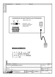
VARIATORE DI LUMINOSITA’ “<strong>DLS</strong>-2<strong>00</strong>”ITALIANOINFORMAZIONI GENERALIIl variatore di luminosità <strong>DLS</strong>-2<strong>00</strong> è un dispositivo elettronico che permette di regolare le luci(incandescenza, led e alogone) presenti sul camper.Può essere collegato a uno o più pulsanti che, premendo un’unica volta accendono espengono la luce predefinita, mentre con una pressione continua variano l’intensità luminosa.L’apparecchio è in grado di gestire distintamente da 1 a 8 canali di luci fino ad una potenzamassima totale di 2<strong>00</strong>W.CARATTERISTICHE TECNICHEALIMENTAZIONE Tensione nominale: 12V Potenza massima totale: 2<strong>00</strong>W (max n°8 canali per max 25W / canale) Uscite regolabili: massimo 8 canali (parallelabili) Carico minimo per canale: 0.1A Protezione: cortocircuito e sovratemperatura Temperatura di esercizio: -0°C +50°C.SEZIONI CAVI DI COLLEGAMENTO CONSIGLIATE Alimentazione 12V : sezione minima consigliata 2.5mm² Uscita luci: sezione minima consigliata 1.5mm² (per canale) Collegamento pulsanti: sezione minima consigliata 0.35mm²CARATTERISTICHE COSTRUTTIVE Dimensioni (mm): 102 x 60 x 30h Peso (kg): 0.1102.6 mm27 mm6352DIMMER “<strong>DLS</strong>-2<strong>00</strong>”12 Vdc2<strong>00</strong>W max1-8 Channels418473POWER SUPPLY LIGHTS PUSH-BUTTONS62511059483726162 mmII4Made in Italy92.6 mm
INSTALLAZIONE- Il dispositivo non è assolutamente adatto all'uso in ambienti esterni e deve essere installatoin un apposito vano, asciutto ed aerato.- L'apparecchio genera calore durante il suo normale funzionamento. Assicurarsi chel'installazione di eventuali altre apparecchiature nelle immediate vicinanze del variatore noncomprometta la normale circolazione di aria e non ne impedisca il necessarioraffreddamento.- Non utilizzare per il collegamento di carici induttivi (motori, ventilatori, ..)- Utilizzare cavi di adeguata sezione.- Proteggere i cavi da ogni possibile danneggiamento.- Proteggere i circuiti d’alimentazione con fusibili dimensionati in base ai carichi collegati.ITALIANONB: Non collegare più di 25W di luci per ogni singolo canale.Per comandare carichi superiori vedi “CONFIGURAZIONE CANALI IN PARALLELO”IMPORTANTE:- L'installazione di questo apparecchio deve essere eseguita solamente da personaletecnico specializzato.- In caso di un utilizzo improprio dell'apparecchiatura, ne decade la garanzia ed ilproduttore declina ogni responsabilità per danni a cose o persone.II5
DESCRIZIONE COLLEGAMENTIITALIANO1632 4 5524138473625110594837261ALIMENTAZIONICOLORE CAVO1 + 12V alimentazione canali di luce “1-2-3-4” edelettronica variatore.Rosso2BIANCO6 5 43 2 1MASSA1) /2) - 12V alimentazione elettronica variatore.3) /4) /5) /6) /COLORE CAVO-Nero----ALIMENTAZIONICOLORE CAVO3 + 12V alimentazione canali di luce “5-6-7-8”Rosso2BIANCO51627384CANALI LUCI (max 25W / canale)1) + Uscita canale luce “5”2) + Uscita canale luce “7”3) + Uscita canale luce “2”4) + Uscita canale luce “1”5) + Uscita canale luce “8”6) + Uscita canale luce “6”7) + Uscita canale luce “3”8) + Uscita canale luce “4”COLORE CAVOBiancoViolaGrigioBluArancioneVerdeGialloMarrone3BIANCO67128394105PULSANTI1) Ingresso pulsante canale luce “5” (-)2) Ingresso pulsante canale luce “7” (-)3) Ingresso pulsante canale luce “2” (-)4) Ingresso pulsante canale luce “1” (-)5) /6) Ingresso pulsante canale luce “8” (-)7) Ingresso pulsante canale luce “6” (-)8) Ingresso pulsante canale luce “3” (-)9) Ingresso pulsante canale luce “4” (-)10) /COLORE CAVOBiancoViolaGrigioBlu-ArancioneVerdeGialloMarrone-II6
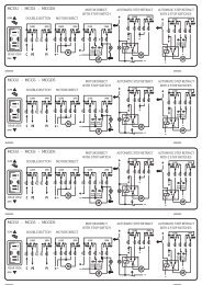
CONFIGURAZIONE CANALI IN PARALLELOIn caso di collegamento di un carico superiore a 25W per canale di luci, è necessario collegare in parallelopiù canali (vedi fig.1).Esempio: Carico luci con potenza 75W, sarà necessario collegare in parallelo 3 canali.ITALIANOFig.1 - Esempio dicollegamento in parallelocanali di luci 1, 2 e 3635241847362511059483726112V+-FUSIBILERossoNeroRossoBluGrigioViolaBluGrigioViolaPULSANTELUCE (max 75W)canali in parallelo“1+2+3”COMANDO CANALI DI LUCI DA PIU’ PUNTINel caso in cui si voglia comandare lo stesso canale da piu punti, è possibile collegare uno o piu pulsanti inparallelo (Fig.2).Fig.2 - Esempio dicollegamentocanale “luce 1”e pulsanti in parallelo12V+-FUSIBILERosso6 53 2Nero41RossoBlu84736 5 10 92 1 5 4PULSANTIBlu837261LUCE (max 25W)canale “1”II7
LIGHT BRIGHTNESS ADJUSTER “<strong>DLS</strong>-2<strong>00</strong>”ENGLISHGENERAL INFORMATIONThe light brightness adjuster <strong>DLS</strong>-2<strong>00</strong> is an electronic device which allows the brightness ofthe motorhome’s internal lights to be varied (resistive incandescent, LED and halogen lights).It can be connected to one or more push buttons installed in the vehicle. By pressing once,lights can be switched on and off while continual pressing varies the light’s brightness.The <strong>DLS</strong>-2<strong>00</strong> can manage up to 8 different light channels up to 2<strong>00</strong>W maximum power.TECHNICAL SPECSPOWER SUPPLY Nominal voltage: 12V Maximum total rating: 2<strong>00</strong>W (max 8 channels each 25W /channel) Adjustable outputs: maximum 8 dimmed light channels (parallelable) Minimum load per channel: 0.1A Protection: Short-circuit and overheating Working temperature: -0°C +50°C.SUGGESTED POWER SUPPLY CABLE SIZECONSTRUCTION CHARACTERISTICSSupply at 12VDimensions (mm): 102 x 60 x 30hWeight (kg): 0.1: suggested minimum section 2.5mm²Light outputs: suggested minimum section 1.5mm² (per channel)Push-button connections: suggested minimum section 0.35mm²102.6 mm27 mm6352DIMMER “<strong>DLS</strong>-2<strong>00</strong>”12 Vdc2<strong>00</strong>W max1-8 Channels418473POWER SUPPLY LIGHTS PUSH-BUTTONS62511059483726162 mmGB8Made in Italy92.6 mm
INSTALLATION- The device is not suited for outdoor use: it must be installed in a specific protected dry andaerated space.- The instrument produces heat during normal operation. Make sure that the installation ofother equipment near the instrument does not hamper the correct air flow and prevent thenecessary instrument cooling.- Do not use the device to power inductive loads (motors, fans, ..)- Use cables with appropriate section.- Protect cables from any possible damage.- Protect the supply circuits using fuses sized as to the loads connected.ENGLISHNB: Do not connect more than 25W lighting load to each single channel.For control of higher loads, see “CONNECTING CHANNELS IN PARALLEL”IMPORTANT:- The installation of this device must be carried out by specialized technicians.- In case of battery charger’s misuse, the guarantee falls off and the manufacturerdeclines all responsibility for damages to people and things.GB9
CONNECTIONSENGLISH1632 4 5524138473625110594837261POWER SUPPLIESCABLE COLOUR1 + 12V Channel “1-2-3-4” power supply andelectronic dimmer power supply.Red2WHITE6 5 43 2 1GROUND1) /2) - 12V electronic dimmer power supply.3) /4) /5) /6) /CABLE COLOUR-Black----POWER SUPPLIESCABLE COLOUR3 + 12V Channel “5-6-7-8” power supplyRed2WHITE51627384LIGHTING CHANNELS (max 25W / channel)1) + Lighting channel output “5”2) + Lighting channel output “7”3) + Lighting channel output “2”4) + Lighting channel output “1”5) + Lighting channel output “8”6) + Lighting channel output “6”7) + Lighting channel output “3”8) + Lighting channel output “4”CABLE COLOURWhitePurpleGreyBlueOrangeGreenYellowBrown3WHITE67128394105BUTTONS1) Light channel button input “5” (-)2) Light channel button input “7” (-)3) Light channel button input “2” (-)4) Light channel button input “1” (-)5) /6) Light channel button input “8” (-)7) Light channel button input “6” (-)8) Light channel button input “3” (-)9) Light channel button input “4” (-)10) /CABLE COLOURWhitePurpleGreyBlue-OrangeGreenYellowBrown-GB10
PARALLEL CHANNEL CONNECTIONIf a higher load than 25W per channel must be connected, channels can be connected in parallel (see fig.1).Example: lighting load 75W = three channels must be connected in parallel.ENGLISHFig.1 – connection exampleparallel lightingchannels 1, 2 and 3635241847362511059483726112V+-FUSERedBlackRedBlueGreyPurpleBlueGreyPurpleBUTTONLIGHT (max 75W)Channels in parallel“1+2+3”CHANNEL CONTROL FROM MORE THAN ONE POSITIONIf the same channel must be controlled from a number of positions, a number of push-buttons can beconnected in parallel (Fig.2).Fig.2 – connection examplechannel “lighting 1”and parallel push-buttons635241847362511059483726112V+-FUSERedBlackRedBlueBUTTONSBlueLIGHT (max 25W)Channel “1”GB11
LICHTHELLIGKEITSREGLER “<strong>DLS</strong>-2<strong>00</strong>”DEUTSCHALLGEMEINE INFORMATIONENDer Lichthelligkeitsregler <strong>DLS</strong>-2<strong>00</strong> ist eine elektonische Steuereinheit, die zur Regelung derHelligkeit von Lampen dient (Glühlampen, LED-Lampen und Halogenlampen).Die Schalt- und Dimmfunktion erfolgt über Tastendruck. Tastendruck kurz um die Lampenein/auszuschalten; Tastendruck lang um die Helligkeit der Lampen zu regeln.Der <strong>DLS</strong>-2<strong>00</strong> kann bis auf 8 getrennte Lichtkanäle max 2<strong>00</strong>W schalten.TECHNISCHE ANGABENSTROMVERSORGUNG Betriebsspannung: 12V max. Gesamtleistung: 2<strong>00</strong>W (max. 8 Kanäle zu max. 25W/Kanal) Regelbare Ausgänge: max. 8 dimmbare Lichtkanäle (parallelfähig) min. Last pro Kanal: 0.1A Schutz: kurzschlussfest und überlastsicher Betriebstemperatur: -0°C +50°C.EMPFOHLENER QUERSCHNITT DER ANSCHLUSSKABEL Stromversorgung 12V : empfohlener Mindestquerschnitt 2.5mm² Lampenausgang: empfohlener Mindestquerschnitt 1.5mm² (pro Kanal) Tastenanschluss: empfohlener Mindestquerschnitt 0.35mm²KONSTRUKTIONSMERKMALE Abmessungen (mm): 102 x 60 x 30h Gewicht (kg): 0.1102.6 mm27 mm6352DIMMER “<strong>DLS</strong>-2<strong>00</strong>”12 Vdc2<strong>00</strong>W max1-8 Channels418473POWER SUPPLY LIGHTS PUSH-BUTTONS62511059483726162 mmDD12Made in Italy92.6 mm
INSTALLATION- Das Gerät darf keinesfalls im Freien verwendet und muss in einem geeigneten, trockenenund belüfteten Raum installiert werden.- Das Gerät erzeugt während seines normalen Betriebs Hitze. Sich dessen versichern, dassdie Installation eventueller anderer Ausrüstungen in der unmittelbaren Nähe des Reglersnicht die normale Luftzirkulation beeinträchtigt und nicht die notwendige Kühlung verhindert.- Nicht für den Anschluss induktiver Lasten verwenden (Motoren, Lüfter usw.)- Kabel mit angemessenen Querschnitt benutzen.- Die Kabel gegen alle mögliche Beschädigungen schutzen- Die Versorgungsschaltkreise durch auf die angeschlossenen Lasten ausgelegteSchmelzsicherungen schützen.DEUTSCHHINWEIS: Die Gesamtleistung der angeschlossenen Lampen pro Kanal darf 25W nicht \überschreiten.Zur Steuerung höherer Lasten siehe „KONFIGURATION VON KANÄLEN INPARALLELSCHALTUNG ”WICHTIG:- Einbau von diesem Gerät darf nur vom einem Fachmann durchgeführt werden- Im Falle vom Mißverbrauch man verwirkt die Garantie und haftet der Herstellerfür keine Sach- oder Personenschaden.DD13
ANSCHLÜSSEDEUTSCH1632 4 5524138473625110594837261VERSORGUNGSKABELKABELFARBE1 + 12V Stromversorgung Lichtkanäle “1-2-3-4” undStromversorgung RegelelektronikRot2WEISS6 5 43 2 1MASSE1) /2) - 12V Stromversorgung Regelelektronik3) /4) /5) /6) /KABELFARBE-Schwarz----VERSORGUNGSKABELKABELFARBE3 + 12V Stromversorgung Lichtkanäle “5-6-7-8” Rot2WEISS51627384LICHTKANÄLE (max 25W /Kanal)1) + Ausgang Lichtkanal “5”2) + Ausgang Lichtkanal “7”3) + Ausgang Lichtkanal “2”4) + Ausgang Lichtkanal “1”5) + Ausgang Lichtkanal “8”6) + Ausgang Lichtkanal “6”7) + Ausgang Lichtkanal “3”8) + Ausgang Lichtkanal “4”KABELFARBEWeissVioletGrauBlauOrangeGrünGelbBraun3WEISS67128394105TASTEN1) Eingang Taste Lichtkanal “5” (-)2) Eingang Taste Lichtkanal “7” (-)3) Eingang Taste Lichtkanal “2” (-)4) Eingang Taste Lichtkanal “1” (-)5) /6) Eingang Taste Lichtkanal “8” (-)7) Eingang Taste Lichtkanal “6” (-)8) Eingang Taste Lichtkanal “3” (-)9) Eingang Taste Lichtkanal “4” (-)10) /KABELFARBEWeissVioletGrauBlau-OrangeGrünGelbBraun-DD14
KONFIGURATION VON KANÄLEN IN PARALLELSCHALTUNGWenn Lasten von über 25W pro Lichtkanal angeschlossen werden sollen, müssen mehrere Kanäle parallelgeschaltet werden (siehe Abb. 1).Beispiel: Bei Anschluss einer Lampe mit 75W Leistung müssen 3 Kanäle parallel geschaltet werden.Abb.1 – Beispiel fürParallelanschlussLichtkanäle 1,2 und 36352418473625110594837261DEUTSCH12V+-SICHERUNGRotSchwarzRotBlauGrauVioletBlauGrauVioletTASTENLAMPE (max 75W)Parallel geschaltete Kanäle“1+2+3”SCHALTEN VON LICHTKANÄLEN VON MEHREREN PUNKTEN AUSWenn die Möglichkeit geschaffen werden soll, einen Lichtkanal von mehreren Punkten aus zu schalten,können eine oder mehrere Tasten parallel geschaltet werden (siehe Abb. 2).Abb.2 – Beispiel fürAnschluss „Lichtkanal 1“mit parallel geschaltetenTasten12V+-SICHERUNGRot6 53 2Schwarz41RotBlau8473625 101 5TASTENBlau94837261LAMPE (max 25W)Kanal “1”DD15
VARIATEUR DE LUMIERE “<strong>DLS</strong>-2<strong>00</strong>”FRANÇAISRENSEIGNEMENTS GÉNÉRAUXLe variateur de luminosité <strong>DLS</strong>-2<strong>00</strong> est un dispositif électronique qui permet de régler leslampes (à incandescence, à diodes électroluminescentes et halogènes) présentes sur lecamping car.Il peut être branché à un interrupteur ou à plusieurs. Il suffit d’appuyer sur l’interrupteur uneseule fois pour allumer une lampe et l’éteindre, alors qu'une pression continue permet dechanger d'intensité lumineuse.L’appareil est en mesure de gérer distinctement de 1 à 8 canaux à lampes jusqu'à unepuissance totale maximale de 2<strong>00</strong>W.CARACTÉRISTIQUES TECHNIQUESALIMENTATION Voltage nominal: 12V Puissance totale maximale: 2<strong>00</strong>W (n°8 canaux maxi pour 25W / canal maxi) Sorties réglables: maximum de 8 canaux (pouvant être mis en parallèle) Charge minimale par canal: 0,1A Protection: court-circuit et excès de température Température d'exercice: 0°C +50°C.SECTIONS DES CÂBLES DE BRANCHEMENT CONSEILLÉES Alimentation 12V : section minimale conseillée de 2.5mm² Sortie lampes: section minimale conseillée de 1.5mm² (par canal) Branchement boutons: section minimale de 0.35 mm² conseilléeCARACTÉRISTIQUES CONSTRUCTIVES Dimensions (mm): 102 x 60 x 30h Poids (kg): 0.1102.6 mm27 mmF166352DIMMER “<strong>DLS</strong>-2<strong>00</strong>”12 Vdc2<strong>00</strong>W max1-8 Channels41POWER SUPPLY LIGHTS PUSH-BUTTONSMade in Italy847362592.6 mm11059483726162 mm
INSTALLATION- Le dispositif n'est absolument pas prévu pour l’extérieur et doit être installé dans unlogement spécial, sec et aéré.- Pendant son fonctionnement normal l'appareil produit de la chaleur. S'assurer quel'installation d'autres appareils dans les environs du variateur ne compromet pas la circulationd'air, en empêchant le refroidissement.- Ne pas utiliser pour le branchement de charges inductives (moteurs, ventilateurs,..)- Utiliser des câbles de section adéquate.- Protéger les câbles de tout endommagement.- Protéger les circuits d'alimentation avec des fusibles dimensionnés en fonction des chargesbranchées.FRANÇAISNB: ne pas brancher plus de 25W de lampes pour chaque canal.Pour commander des charges supérieures, il faut se reporter au chapitre“CONFIGURATION CANAUX EN PARALLÈLE”IMPORTANT:- L'installation de cet appareil doit être faite seulement par un technicien spécialisé- En cas d'emploi abusif de l'appareil, la garantie déchue et le fabricantdécline toute responsabilité pour les dégâts causés à choses ou personnes.F17
BRANCHEMENTSFRANÇAIS1632 4 55241384736251105948372611ALIMENTATIONS+ 12V alimentation canaux à lampes “1-2-3-4” etalimentation variateur électroniqueCOULEUR CÂBLERouge2BLANC6 5 43 2 1MASSE1) /2) - 12V alimentation variateur électronique.3) /4) /5) /6) /COULEUR CÂBLE-Noir----3ALIMENTATIONS+ 12V alimentation canaux à lampes “5-6-7-8”COULEUR CÂBLERouge2BLANC51627384CANAUX LAMPES (max 25W / canal)1) + sortie canal lampe “5”2) + sortie canal lampe “7”3) + sortie canal lampe “2”4) + sortie canal lampe “1”5) + sortie canal lampe “8”6) + sortie canal lampe “6”7) + sortie canal lampe “3”8) + sortie canal lampe “4”COULEUR CÂBLEBlancVioletGrisBleuArancioneOrangeJauneMarron3BLANC67128394105BOUTONS1) entrée canal interrupteur lampe “5” (-)2) entrée canal interrupteur lampe “7” (-)3) entrée canal interrupteur lampe “2” (-)4) entrée canal interrupteur lampe “1” (-)5) /6) entrée canal interrupteur lampe “8” (-)7) entrée canal interrupteur lampe “6” (-)8) entrée canal interrupteur lampe “3” (-)9) entrée canal interrupteur lampe “4” (-)10) /COULEUR CÂBLEBlancVioletGrisBleu-ArancioneOrangeJauneMarron-F18
CONFIGURATION DE CANAUX EN PARALLÈLEPour le branchement d'une charge dépassant 25W par canal à lampes, il faudra brancher plusieurs canauxen parallèle (cf. fig.1).Exemple: pour une charge de lampes avec une puissance de 75W, il faudra brancher 3 canaux en parallèle.Fig.1 - Exemple debranchement en parallèlecanaux à lampes 1, 2 et 36352418473625110594837261FRANÇAIS12V+-FUSIBLERougeNoirRougeBleuGrisBlancBleuGrisBlancBOUTONLAMPE (MAX 75W)canaux en parallèle“1+2+3”COMMANDE DE CANAUX À LAMPES À PARTIR DE PLUSIEURS ENDROITSSi l’on veut commander le même canal à partir de plusieurs endroits, il est possible de brancher uninterrupteur ou plusieurs en parallèle (Fig.2).Fig.2 - Exemple debranchementcanal « lampe 1 »et boutons en parallèle12V+-FUSIBLERouge6 53 2Noir41RougeBleu84736 5 10 92 1 5 4BOUTONSBleu837261LAMPE (MAX 25W)canal “1”F19
I dati riportati nei fogli di istruzioni possono subire modifiche senza preavviso alcuno, questo è dovutoalle continue migliorie tecniche. I disegni e i testi riprodotti sono proprietà della CBE. E' vietata lariproduzione integrale o parziale e la comunicazione a terzi senza l'autorizzazione scritta.Technical data on instructions sheets can be modified without notice, because technicalimprovements are continually made. Design and texts are CBE property. Integral or partialreproductions are not admitted as well as communications to third parties without written permission.Die in den Gebrauchsanweisungen geführten Daten können ohne Vorankündigung geändertwerden, in Zusammenhang mit den technischen Verbesserungen. Die veröffentlichten Abbildungenund Texte sind Eigentum der Fa. CBE. Jegliche Art von Vervielfältigung, komplett oder teilweise, istohne schriftliche Genehmigung untersagt.Les données reportées dans les pages des instructions peuvent subir des modifications sans aucunpréavis ,ceci en vue des continuelles améliorations techniques. Les dessins et les textes reproduitssont de propriété de la CBE. La reproduction totale ou partielle et la communication à tiers, sansautorisation écrite sont interdites.CBE S.r.l.Via Vienna, 4 - z.i. Spini (settore D)38121 Trento - ItalyTel. +39 0461 991598 - Fax +39 0461 96<strong>00</strong>09www.cbe.it - E-mail: cbe@cbe.it