306 224 391 106 - 001 - 13/06 Fiat Stilo Erweiterung 06 ... - Westfalia
306 224 391 106 - 001 - 13/06 Fiat Stilo Erweiterung 06 ... - Westfalia
306 224 391 106 - 001 - 13/06 Fiat Stilo Erweiterung 06 ... - Westfalia

You also want an ePaper? Increase the reach of your titles
YUMPU automatically turns print PDFs into web optimized ePapers that Google loves.
.......................................................................................................Einbauanleitung:Elektroanlage für Anhängevorrichtung .....................................................................................................................................................................Instructions de montage :Installation électrique pour dispositif d’attelage ......................................................................................................................................................Installation instructions:Electrical system for towing hitch..............................................................................................................................................................................Istruzioni per l'installazione:Impianto elettrico per il gancio di traino ...................................................................................................................................................................Inbouwinstructie:Elektrische installatie voor trekhaak ..........................................................................................................................................................................Návod k montáži:Elektrické za2ízení pro záv4sné za2ízení.............................................................<strong>3<strong>06</strong></strong> <strong>224</strong> <strong>391</strong> <strong>1<strong>06</strong></strong> - <strong>001</strong> - <strong>13</strong>/<strong>06</strong> <strong>Fiat</strong> <strong>Stilo</strong> <strong>Erweiterung</strong> <strong>06</strong>-
Instructions de montage :Installation électrique pour dispositif d’attelage<strong>Westfalia</strong><strong>Fiat</strong><strong>3<strong>06</strong></strong> <strong>224</strong> 300 xxx Vorab Info <strong>Fiat</strong> <strong>Stilo</strong> und <strong>Stilo</strong> MultiWagon11 2 32 <strong>3<strong>06</strong></strong> <strong>224</strong> <strong>391</strong> <strong>1<strong>06</strong></strong> - <strong>001</strong> - <strong>13</strong>/<strong>06</strong> <strong>Fiat</strong> <strong>Stilo</strong> <strong>Erweiterung</strong> <strong>06</strong>-
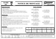
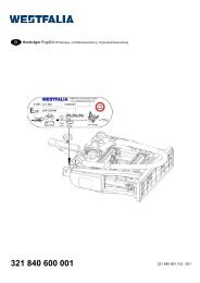
Instructions de montage :Installation électrique pour dispositif d’attelageEinbauanleitung:Elektroanlage für AnhängevorrichtungWichtige HinweiseVor Arbeitsbeginn die Einbauanleitung lesen.Der Elektroeinbausatz darf nur von qualifiziertem Fachpersonal eingebaut werden.Vorsicht – Batterie abklemmen!Beschädigung der KFZ-Elektronik, elektronisch gespeicherte Daten können verlorengehen.Vor Arbeitsbeginn den Fehlerspeicher auslesen.Ggf. ein Ruhestrom-Erhaltungsgerät verwenden.Die Prüfung der Anhängerfunktionen mit einem Anhänger oder einem Prüfgerät mitBelastungswiderständen durchführen.Technische Änderungen vorbehalten!Elektroeinbausatz einbauen1. Minusklemme der Batterie abklemmen.2. Reserverad entnehmen.3. Folgende Abdeckungen und Verkleidungen ggf. entfernen:• Im Kofferraum- Verkleidung der rechten Seite des Kofferraumes- Verkleidung unter der Rücksitzbank4. 20<strong>06</strong>-: Ergänzungsleitung mit dem 2-poligen Stecker unterhalb der rechten Rückleuchte(Abb. ½ ) verbinden. Rote Leitung geeignet unter die Rücksitzbank (Abb. 1/1) verlegen und indie freie Kammer A2 des 24-pol. grauen Stecker einsetzen und verrasten.Besonderheiten bei Fahrzeugen mit Einparkhilfe (EPH)Für Modelle ab 20<strong>06</strong>:4. Die braun/weiße Leitung zum Steuergerät der EPH (Abb. 1/3) verlegen.5. Den 16-poligen Stecker öffnen und den Kontakt der braun/weißen Leitung in Kammer 5einsetzen.6. Stecker schließen und wieder auf das Steuergerät der EPH stecken.Hinweis: Ist keine EPH vorhanden, braun/weiße Leitung isolieren und fachgerechtbefestigen.Funktion prüfen7. Masse der Fahrzeugbatterie wieder anschließen.8. Die Anhängerfunktionen mit einem geeigneten Prüfgerät (mit Belastungswiderständen) odermit einem Anhänger prüfen.9. Alle Leitungen mit Kabelbindern befestigen.10. Alle ausgebauten Teile wieder einbauen.<strong>Fiat</strong> <strong>Stilo</strong> <strong>Erweiterung</strong> <strong>06</strong>- <strong>3<strong>06</strong></strong> <strong>224</strong> <strong>391</strong> <strong>1<strong>06</strong></strong> - <strong>001</strong> - <strong>13</strong>/<strong>06</strong> 3
Instructions de montage :Installation électrique pour dispositif d’attelageInstructions de montage :Installation électrique pour dispositif d’attelageRemarques importantesAvant de commencer l'intervention, lire les instructions d'installation.L'installation du module électronique ne doit être réalisée que par des techniciens qualifiés.Attention – débrancher la batterie !Endommagement de l'électronique du véhicule, les données enregistréesélectroniquement peuvent être perdues.Extraire la mémoire des erreurs avant de commencer l'intervention.Le cas échéant, utiliser un dispositif de maintien de courant permanent.Installation du module électronique1. Débrancher la borne négative de la batterie.2. Retirer la roue de secours.3. Le cas échéant, retirer les revêtements et garnitures suivants :• Dans le coffre- Revêtement du côté droit du coffre à bagages- Revêtement sous la banquette arrière4. 20<strong>06</strong>-: Relier le fil complémentaire avec le connecteur 2 pôles ( FIG.1/2) sous le feu arrièredroit. Placer le fil rouge de manière adéquate sous la banquette arrière (Fig. 1/1) et l'insérerdans le logement libre A2 de la fiche grise 24 pôles.Particularités pour les véhicules équipés d'un système d'aide au stationnement(EPH)Pour les modèles à partir de 20<strong>06</strong> :5. Relier le fil marron/blanc sur le dispositif de commande du système d’aide au stationnement(EPH) (Fig. 1/3).6. Ouvrir la fiche 16 pôles et insérer le contact du fil marron/blanc dans le logement 5.7. Fermer la fiche et l’insérer de nouveau sur le dispositif de commande du système d’aide austationnement (EPH).Remarque : Si aucun système d’aide au stationnement (EPH) est disponible, isoler le filmarron/blanc et bien serrer.Vérifier le fonctionnement8. Reconnecter la masse de la batterie du véhicule.9. Vérifier le fonctionnement de l'attelage avec un dispositif de contrôle adéquat (avecrésistance fixe) ou avec un attelage.10. Fixer tous les fils avec des attaches-câbles.11. Remonter toutes les pièces qui ont été démontées.4 <strong>3<strong>06</strong></strong> <strong>224</strong> <strong>391</strong> <strong>1<strong>06</strong></strong> - <strong>001</strong> - <strong>13</strong>/<strong>06</strong> <strong>Fiat</strong> <strong>Stilo</strong> <strong>Erweiterung</strong> <strong>06</strong>-
Installation instructions:Electrical system for towing hitchInstallation instructions:Electrical system for towing hitchImportant notesRead the installation manual prior to starting work.The electrical kit should only be installed by qualified personnel.Caution – Disconnect the battery!Danger of damage to the vehicle’s electronic system. Data which are storedelectronically may get lost.Read out the fault storage prior to starting work.Use a closed-circuit current conservation unit if necessary.Installing the electrical kit1. Disconnect the negative battery terminal.2. Remove the spare wheel.3. If necessary, remove the following covers and panels:• In the luggage compartment- Covering of the right trunk side- Covering under the rear seat bench4. 20<strong>06</strong>-: Connect the auxiliary cable to the 2-pin connector ( FIG.1/2) below the tail light on theright. Lay the red cable in a suitable manner under the rear seat bench (Fig. 1/1), plug it intothe free A2 compartment of the grey 24-pin connector and lock it in place.Special information concerning vehicles with parking distance control (PDC)On vehicles with PDC it is possible to deactivate the PDC for trailer operation. Already included inmodels up to 2005!For models as of 20<strong>06</strong>:5. Lay the brown/white cable to the PDC control unit (Fig. 1/3).6. Open the 16-pin plug and insert the contact of the brown/white cable into compartment 5.7. Close the plug and plug it back into the PDC control unit.Note: If the vehicle is not equipped with a PDC system, insulate the brown/white cable andsecure it properly.Checking correct operation8. Reconnect the ground of the vehicle’s battery.9. Check the trailer function with the help of a suitable test instrument (with load resistors) orwith the help of a trailer.10. Secure all cables using cable ties.11. Reattach any parts removed for installation.<strong>Fiat</strong> <strong>Stilo</strong> <strong>Erweiterung</strong> <strong>06</strong>- <strong>3<strong>06</strong></strong> <strong>224</strong> <strong>391</strong> <strong>1<strong>06</strong></strong> - <strong>001</strong> - <strong>13</strong>/<strong>06</strong> 5
Istruzioni per l'installazione:Impianto elettrico per il gancio di trainoIstruzioni per l'installazione:Impianto elettrico per il gancio di trainoNote importantiPrima di iniziare i lavori, leggere le istruzioni di montaggio.Il kit elettrico deve essere montato solo da personale qualificato.Attenzione – Staccare la batteria!Danni all'elettronica del veicolo, i dati memorizzati possono essere persi.Prima di iniziare consultare la memoria degli errori.Se necessario, utilizzare un apparecchio di mantenimento della corrente di riposo.Montaggio del kit elettrico1. Staccare il morsetto negativo dalla batteria.2. Togliere la ruota di scorta.3. Togliere eventualmente le seguenti coperture e rivestimenti:• Nel bagagliaio- rivestimento del lato destro del bagagliaio.- Rivestimento sotto la panchina posteriore4. 20<strong>06</strong>-: Collegare il conduttore complementare alla spina a 2 poli sotto il fanale posterioredestro. Posare il conduttore rosso sotto la panchina posteriore (fig. 1/1) ed inserirlo ebloccarlo nella camera libera A2 della spina grigia a 24 poli.Particolarità per veicoli corredati di aiuto al parcheggio (EPH)In caso di veicoli con EPH esiste la possibilità di escludere la EPH in caso di impiego di rimorchi.Nei modelli fino al 2005 già in dotazione.Per modelli a partire dal 20<strong>06</strong>:5. Posare il cavo marrone/bianco fino alla centralina di comando dell'EPH (fig. 1/9).6. Aprire la spina a 16 poli ed inserire il contatto del conduttore marrone/bianco nella camera 5.7. Richiudere la spina ed innestarla di nuovo sulla centralina di comando dell'EPH.Nota: se l'EPH non è presente, isolare il conduttore marrone/bianco e fissarlo correttamente.Verifica del funzionamento8. Ricollegare la massa della batteria del veicolo.9. Verificare il funzionamento del rimorchio mediante dispositivo idoneo (con resistenze dicarico) o collegando il rimorchio stesso.10. Fissare tutti i cavi con fascette stringicavo.11. Rimontare tutte le parti smontate precedentemente.6 <strong>3<strong>06</strong></strong> <strong>224</strong> <strong>391</strong> <strong>1<strong>06</strong></strong> - <strong>001</strong> - <strong>13</strong>/<strong>06</strong> <strong>Fiat</strong> <strong>Stilo</strong> <strong>Erweiterung</strong> <strong>06</strong>-
Inbouwinstructie:Elektrische installatie voor trekhaakInbouwinstructie:Elektrische installatie voor trekhaakBelangrijke opmerkingenLees voor begin van de werkzaamheden de montagehandleiding door.De elektrische montageset mag uitsluitend worden gemonteerd door gekwalificeerd personeel.Pas op – accu afklemmen!Beschadiging van de voertuigelektronica, elektronisch bewaarde gegevens kunnenverloren gaan.Voor begin van de werkzaamheden foutgeheugen uitlezen.Zo nodig een ruststroom-behoudgedeelte gebruiken.OpmerkingLet bij de montage vooral op de volgende punten:• Kabels mogen noch worden ingeklemd noch beschadigd.• Alle dichtingselementen bevestigen zoals voorgeschreven.• Kabels zo leggen dat deze noch aan het voertuig wrijven noch knikken.12. 20<strong>06</strong>-: Extra kabel met de 2-polige stekker (afb.1/2) beneden de rechter achterlampverbinden. Rode kabel op een daartoe geschikte wijze beneden de achterbank (afb. 1/1)leggen, in het vrije vak A2 van de 24-polige grijze stekker plaatsen en vergrendelen.Bijzonderheden bij voertuigen met parkeerhulpBij voertuigen met parkeerhulp bestaat de mogelijkheid deze gedurende het rijden metaanhangwagen te deactiveren. Bij modellen tot 2005 al meegeleverd!Voor modellen vanaf 20<strong>06</strong>:<strong>13</strong>. De bruin/witte kabel naar het regelapparaat van de parkeerhulp (afb. 1/9) leggen.14. De 16-polige stekker openen en het contact van de bruin/witte kabel in kamer 5 plaatsen.15. Stekker sluiten en weer op het regelapparaat van de parkeerhulp aansluiten.Opmerking: Wanneer geen parkeerhulp gemonteerd is, de bruin/witte kabel isoleren envakkundig vastmaken.Functie controleren16. De massa van de accu weer aansluiten.17. De aanhangerfuncties m.b.v. een geschikt testapparaat (met belastingsweerstanden) of meteen aanhanger controleren.18. Alle kabels met kabelbinders bevestigen.19. Alle gedemonteerde onderdelen weer plaatsen.<strong>Fiat</strong> <strong>Stilo</strong> <strong>Erweiterung</strong> <strong>06</strong>- <strong>3<strong>06</strong></strong> <strong>224</strong> <strong>391</strong> <strong>1<strong>06</strong></strong> - <strong>001</strong> - <strong>13</strong>/<strong>06</strong> 7
Návod k montáži:Elektrické za2ízení pro záv4sné za2ízeníNávod k montáži:Elektrické za2ízení pro záv4sné za2ízeníDIležitá upozorn4níPRed zaSátkem práce si pReStUte návod k montáži.Elektrickou sadu smí instalovat pouze kvalifikovaný odborný personál.Pozor – odpojte akumulátor!Poškození elektroniky motorového vozidla, pRípadná ztráta elektronicky do pamUtiuložených dat.PRed zaSátkem práce vyStUte pamUZ poruch.EventuálnU použijte pRístroj na udržování klidového proudu.Upozorn4níPRi montáži mUjte na zReteli pRedevším následující body:• Vedení nesmí být uskRípnuta nebo poškozena.• Instalujte RádnU všechny tUsnicí prvky.• VodiSe instalujte tak, aby se nedRely o vozidlo nebo se nenalomily.20. 20<strong>06</strong>-: DodateSné vedení spojte s dvoupólovým konektorem pod pravým koncovým svUtlem.\ervené vedení ve]te vhodným zp^sobem po zadní sedadlo (obr. 1/1) a vsa]te a zajistUte jeve volném pRedUlu A2 24pól. šedého konektoru.Zvláštnosti u vozidel s pomIckou pro parkování (EPH)U vozidel s EPH, m^žete EPH pro provoz s pRívUsem deaktivovat. U model^ do 2005 jižobsaženo!Pro modely od 20<strong>06</strong>:21. Ve]te hnUdobílý vodiS k Rídicí jednotce pom^cky pro parkování (EPH) (obr. 1/9).22. OtevRete šestnáctipólovou zástrSku a vsa]te kontakt hnUdobílého vodiSe do pRedUlu 5.23. UzavRete zástrSku a spojte ji opUt s Rídicí jednotkou EPH.Upozorn4ní: Neexistuje-li žádná pom^cka pro parkování, izolujte a odbornU pRipevnUtehnUdobílý vodiS.Kontrola funkce24. UkostRete opUt baterii vozidla.25. Funkce pRívUsu pRekontrolujte vhodným kontrolním pRístrojem (se zatUžovacími odpory), neboprostRednictvím pRívUsu.26. Všechna vedení pRipevnUte kabelovými svorkami.27. Všechny vymontované díly opUt zamontujte.8 <strong>3<strong>06</strong></strong> <strong>224</strong> <strong>391</strong> <strong>1<strong>06</strong></strong> - <strong>001</strong> - <strong>13</strong>/<strong>06</strong> <strong>Fiat</strong> <strong>Stilo</strong> <strong>Erweiterung</strong> <strong>06</strong>-